EP0070137A1 - Détecteurs de vitesse de variation de température, et systèmes d'alarme de feu et d'extinction de feu utilisant de tels détecteurs - Google Patents
Détecteurs de vitesse de variation de température, et systèmes d'alarme de feu et d'extinction de feu utilisant de tels détecteurs Download PDFInfo
- Publication number
- EP0070137A1 EP0070137A1 EP82303530A EP82303530A EP0070137A1 EP 0070137 A1 EP0070137 A1 EP 0070137A1 EP 82303530 A EP82303530 A EP 82303530A EP 82303530 A EP82303530 A EP 82303530A EP 0070137 A1 EP0070137 A1 EP 0070137A1
- Authority
- EP
- European Patent Office
- Prior art keywords
- detector
- detector according
- temperature
- elements
- rate
- Prior art date
- Legal status (The legal status is an assumption and is not a legal conclusion. Google has not performed a legal analysis and makes no representation as to the accuracy of the status listed.)
- Ceased
Links
Images


Classifications
-
- H—ELECTRICITY
- H01—ELECTRIC ELEMENTS
- H01H—ELECTRIC SWITCHES; RELAYS; SELECTORS; EMERGENCY PROTECTIVE DEVICES
- H01H37/00—Thermally-actuated switches
- H01H37/02—Details
- H01H37/32—Thermally-sensitive members
- H01H37/323—Thermally-sensitive members making use of shape memory materials
-
- H—ELECTRICITY
- H01—ELECTRIC ELEMENTS
- H01H—ELECTRIC SWITCHES; RELAYS; SELECTORS; EMERGENCY PROTECTIVE DEVICES
- H01H61/00—Electrothermal relays
- H01H61/01—Details
- H01H61/0107—Details making use of shape memory materials
- H01H2061/0115—Shape memory alloy [SMA] actuator formed by coil spring
Definitions
- the present invention relates to rate of temperature change detectors particularly though not exclusively for use as "rate of rise” fire detectors, and to fire alarm and fire extinguishing systems employing such detectors.
- SME shape memory-effect
- An SME element is made from a material, usually an alloy, which undergoes a transformation in its crystallographic structure when heated or cooled through a particular temperature range, this transformation being accompanied by a significant change in elastic modulus.
- the element can be arranged to exhibit a first stable shape at temperatures below the appropriate transofrmation range and a different stable shape at temperatures above that range, the element being capable of changing reversibly between its low and high temperature shape conditions when heated and cooled through the transformation range. In other words the element behaves in a manner indicative of retaining a "memory" for either shape.
- Such elements are know, examples of alloys which exhibit the shape memory effect including certain nickel-titanium and copper-zinc-aluminium alloys.
- rate of temperature change detector An important application for a rate of temperature change detector according to the invention is as a so-called "rate of rise" fire detector.
- Such devices must be capable of responding primarily to specified rates of increase in ambient temperature in the region monitored, as opposed to the absolute (ie instantaneous) value of temperature, although it is desirable that they shall also respond to a predetermined maximum ambient temperature irrespective of the rate of change of temperature at that time.
- the specified upper limits of response time to the given rates of rise of temperature are of course intended to ensure that detectors respond sufficiently quickly to a fire, while a lower limit of response time is also specified in order to minimise the incidence of false alarms due to changes in the ambient temperature where no fire has occurred.
- the upper and lower limits to the absolute temperature to which detectors must respond under "static" conditions are specified for similar reasons.
- the invention provides in one aspect a rate of temperature change detector comprising two shape memory effect elements each one of which is adapted to respond to specified changes of temperature within a region wherein the detector is, in use, disposed; the response exhibited by a first said element tending to provide an output from the detector; the second said element being coupled to the first element whereby the response exhibited by the second element opposes the response of the first element; and the arrangement being such that the two said elements respond at different effective rates to the same change of temperature in the region.
- the response of the first SME element tending to provide an output while the response of the second SME element opposes the first element, the time taken for an output to be provided when.the monitored region exhibits a given rate of change of temperature is therefore determined by the relative effective rates of response of the two elements , which can be chosen to confer upon the device characteristics approprate to a "rate of rise" fire detector or to such other use as may be required.
- means are also provided for limiting the response which can be exhibited by the second element in opposition to the first element, so that any further change of temperature which occurs after that response of the second element will result in an effective response by the first element only, leading inevitably to the provision of an output when a certain absolute temperature is reached and thereby ensuring the requisite "static" operation of the detector.
- the different effective rates of response of the two SME elements could be achieved by employing elements with different inherent thermomechanical properties, such as with different alloy compositions. It is generally more covenient, however, to employ two similar elements and to provide for the different rates of response by arranging that temperature changes occurring in the monitored region are transmitted to the first element more rapidly than to the second element, such as by surrounding the second element with structure of a lower thermal transmissivity than that (if any) surrounding the first element and/or by coating the second element with heat insulative material.
- the form of the SME elements comprised in a detector according to the invention is open to considerable variation.
- One preferred form comprises a cylindrical coil of shape memory effect material which element tends to expand axially when heated through the transformation temperature range of the material.
- a second preferred form comprises a flat spiral of the material which tends to expand in part-conical form when heated through the transformation temperature range, and a third preferred form is in effect the opposite, namely a part-conical spiral of the material which tends to contract towards a flat spiral form when heated through the transformation range.
- each such SME element will be fixed in position at one location upon the respective element while another location upon that element is capable of displacing relative to the one location upon change of temperature of the element through the transformation range.
- substantial spatial movement of part of an element need not always be an essential to operation of a detector according to the invention where, for example, the element is constrained against movement and the variation in force applied to the constraining means by the element as it undergoes its crystallographic transformation in the appropriate temperature range is detected.
- a two-stage type of response may be exhibited, where for example the aforesaid first element must first overcome a biasing load as it transforms under change of temperature and thereafter deflects by a small distance to provide an output from the detector.
- the output from a detector as defined above may be used to exert a control and/or to give an indication as appropriate to the use to which the detector is put.
- a device is particularly useful in fire detection and in a second aspect the invention resides in a fire alarm system comprising at least one detector according to the first aspect of the invention sensitive to the rate of increase of temperature within a respective region and means responsive to the output of the or any such detector to indicate the existance of an alarm condition.
- the invention resides in a fire- extinguishing system comprising at least one detector according to the first aspect of the invention sensitive to the rate of increase of temperature within a respective region, and means responsive to the output of the or any such detector to initiate the delivery of a fire extinguishing agent into the respective region.
- the illustrated detector is assumed to be mounted to the ceiling of a room and to be one of a plurality of fire detectors distributed throughout a building, all connected electrically to a central control station (not shown). It comprises a plastics casing 1 within which is mounted a cup-shape plastics sleeve member 2 which in turn serves for the mounting of a cylindrical coil 3 of SME alloy and other parts of the mechanism to be described below. The two or so turns at the centre of the coil 3 are held rigidly by the member 2 and play no part in the actual operation of the device.
- the portions 4 and 5 of the coil 3 to either side of this central portion are not rigidly restrained and are appropriately treated such that below a particular temperature they exhibit a compressed form but when heated through the transformation temperature range of the alloy (preferably a brass) of which the coil is made they increase in stiffness and thereby extend axially. Since the coil portions 4 and 5 are parts of the same continuous element 3 and since they receive identical treatement during the manufacture of that element, their thermomechanical properties are substantially the same, which means that (in the absence of external constraints) when they are heated to the same temperature portion 4 will tend to extend upwardly from the central coil portion by the same distance as portion 5 extends downwardly.
- the free end of the upper SME coil portion 4 engages a flange 6 towards the upper end of a sleeve 7 disposed within the coil 3.
- a further sleeve 8 is disposed in telescoping relationship with the sleeve 7 and these two components are coupled together resiliently through an ordinary (ie non-SME) coil spring 9 compressed between webs 10 and 11 at the respective lower ends of the sleeves 7 and 8.
- the free end of the lower SME coil portion 5 engages the head 12 of a rod 13 which extends upwardly through the two sleeves 7 and 8 and carries at its upper end a smaller head, defined by a snap ring 14 fast with the rod, which is disposed in telescoping relationship within the upper sleeve 8.
- This rod 13 is coupled resiliently to the sleeve 8 through an ordinary coil spring 15 equivalent to the spring 9 and compressed betwen the web 11 and ring 14.
- the sleeve 8 is effectively suspended, by means of the two springs 9 and 15, acting on opposite sides of its web 11, between the web 10 of sleeve 7 and the ring 14 fastened to rod 13, and that the position of the sleeve 8 with respect to the fixed structure of the detector is thereby determined at all times by the relative positions of the rod 13 and sleeve 7.
- the sleeve 7 carries an electrical contact 16 which is normally spaced from a fixed contact 17 mounted to the member 2, but if the sleeve 8 is moved downwardly through an appropriate distance the two contacts are brought together to complete an electrical circuit and this event is detected at the control station, via suitable leads (not shown), as an indication of fire.
- the alignment between the two contacts during this movement is maintained by a pair of cheeks 22 (of which one is seen in the Figure) provided on the member 2 and extending to either side of the contact 16.
- the tendency of extension of the lower SME coil portion 5 is to move the rod 13 downwards, thereby tending also to move the sleeve 8 and contact 16 downwards by further compression of the springs 9 and 15.
- the tendency of extension of the upper SME coil portion 4 is to oppose the extension of portion 5, through the resilient coupling provided by springs 9 and 15. It has been indicated that the response of the two SME coil portions 4 and 5 to equivalent temperatures is to extend by equal amounts; their response to thermal conditions outside the detector structure is not, however, the same, and this can be explained by considering the relative dispositions of the two coil portions with respect to the external ambience.
- the upper coil portion 4 is surrounded by structure Y,2 of low thermal transmissivity.
- the lower coil portion 5 is surrounded by a thin, thermally transmissive sheath 18, of copper or aluminium for example.
- the casing 1 may be extended, as shown, as a series of "claws" 19 in the vicinity of the sheath 18 to provide impact protection for that area of the device, but these claws are spaced apart and well ventilated such that they do not significantly impair heat transmission from the surrounding environment to the sheath. It follows that any fluctuations in the air temperaure of the region in which the detector is sited will be transmitted to the lower SME coil portion 5 more rapidly than they are transmitted to the upper coil portion 4.
- both coil portions 4 and 5 remain in their compressed condition, as illustrated, and the contact 16 remains spaced from the contact 17.
- both coil portions 4 and 5 will begin to extend, but as the lower coil portion 5 has a quicker response to rising temperature in the monitored region, as explained above, its extension will lead the extension of portion 4. Due to this differential extension of the two SME coil portions there is a net movement of the sleeve 8 and contact 16 in the downward direction.
- This is a ring which is screwed into the member 2 and has a flange 21 which lies in the path of movement of the flange 6 of sleeve 7 when the upper SME coil portion 4 extends.
- the contact 16 is in threaded engagement with the sleeve 8 so that relative rotation of these two parts adjusts their relative axial positions.
- this provides a means of setting the initial spacing of the contact 16 from the contact 17 to ensure appropriate "rate of rise" response times from the device.
- the ring 20 can be screwed in or out of the member 2 to adjust the distance through which the upper SME coil portion 4 extends before its movement is terminated, thereby to ensure appropriate "static" response from the device.
- FIG 2 shows a rate of rise fire detector comprising two separate SME elements 23 and 24 of different form to the "elements" 4 and 5 in the Figure 1 embodiment.
- each element is formed and heat treated to have a flat spiral shape at temperatures below the transformation range, as more clearly seen in Figure 3, and to expand progressively in part-conical helical form with rise of temperature through that range, the unconstrained high-temperature form of these elements being indicated in Figure 4.
- the element 23 is held flat against the base of a thermally conductive sheath 25 of eg copper or aluminium, by a plastics spacer 26 engaging its outermost turn (the spacer comprising two rings 26A interconnected by a series of webs 26B), and by a plastics moulding 27 held in the centre of the element.
- the sheath 25 is held in plastics casing 28 which may, as in the case of Figure 1, be extended downwardly around the sheath in a series of protective but ventilated "claws" 29.
- a platform 30 is held in the casing 28 by an upper housing member 31 screwed into the casing, and in the illustrated low temperature condition of the device the second SME element 24 is held flat against this platform, above and spaced from the element 23, by the spacer 26 engaging its outermost turn and by a plstics moulding 32 held in the centre of the element.
- the two mouldings 27 and 32 are biased apart by an ordinary coil spring 33.
- the moulding 32 has an integral stem part 34 which is slidably borne in a central bore 35 of the platform 30.
- a rod 36 is in turn slidably borne by the moulding/stem 32/34 and seats at its lower end in a recess 37 in the moulding 27.
- the rod 36 carries a metal cap 38 which functions as a moving electrical contact, normally spaced from a stationary (but adjustable) contact 39 screwed into the housing member 31.
- a further ordinary coil spring 40 is compressed between the cap 38 and the housing member 31.
- the two elements 23 and 24 are identical in manufacture and, as has been indicated, their tendency when heated through the relevant transformation temperture range is to expand in a part-conical form.
- Element 23 is mounted with its outer turn fixed in position by spacer 26 and is arranged to expand upwards so that its central part carries the moulding 27 upwards when such expansion occurs.
- Element 24 is mounted in opposition to element 23 with its outer turn fixed in position by spacer 26 and is arranged to expand downwards so that its central part carries the moulding 32 downwards when such expansion occurs.
- the axial position of the rod 36 and cap 38 is determined by the position of the central part of the element 23, the cap 38 being moved to close the electrical contact gap between itself and contact 39 when the element 23 has expanded through a predetermined distance.
- Element 23 is in heat conductive relationship with the sheath 25 so that temperature fluctuations occurring in the region where the detector is sited are very quickly transmitted to that element.
- the element 24 is, however, relatively isolated from temperature changes outside the detector and its own temperature will not rise so rapidly as that of element 23 when a detectable rate of increase in ambient temperature occurs. It will be noted, though, that element 24 is biased towards its flat condition by the load in spring 33, whereas element 23 is biased towards its flat condition by both the load in spring 33 and the load in spring 40.
- a nut 41 is threaded on to the end of the stem 34, which nut comes into abutment with the platform 30 to prevent further expansion of element 24 after it has moved through a predetermined distance and thereby limits the bias applied to element 23 by element 24.
- Calibration of the device as appropriate for its "rate of rise” and “static” response can be achieved by adjusting the position of the contact 39 in the housing member 31 and adjusting the position of the nut 41 along the stem 34, respectively.
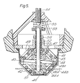
- the detector of Figure 5 has much in common with the embodiment of Figure 2 and once again makes use of two separate SME elements which are capable of undergoing a transformation between a flat spiral form and an expanded part-conical form.
- the low and high-temperature forms of the elements are reversed so that, as shown in the Figure, at temperatures below the transformation range the two elements 42 and 43 are in the part-conical form.
- the lower element 42 is held in contact with a thermally conductive sheath 44 of complementary shape, by a plastics spacer ring 45 engaging its outermost turn and by a plastics moulding 46 held in the centre of the element.
- the upper element 43 is held against a platform 47 and complementary backing member 48 by the spacer ring 45 engaging its outermost turn and by a plastics moulding 49 held in the centre of the element.
- the mouldings 46 and 49 are each provided with a circumferential series of inclined fingers 46A and 49A which support the respective elements 42/43 internally.
- the moulding 49 has an integral stem part 50 which is slidably borne in the platform 47. Also provided are a spring 51, rod 52, cap 53, contact 54, further spring 55 and nut 56, functionally equivalent to the components' 33,36,38,39,40 and 41 respectively of the Figure 2 detector.
- the operation of this detector is therefore completely analgous to that of the Figure 2 embodiment, in ths case the SME elements 42 and 43 tending to contract towards the flat form to displace the respective mouldings 46 and 49 when heated through the transformation range.
- the thermally- conductive sheath 18, 25 or 44 may be fluted (eg as indicated at 44A in Figure 5) or otherwise augmented (eg with one or more fins as indicated at 44B in Figure 5) to increase the surface area of the sheath available for heat- collection from the environment.
- the various biasing springs in any embodiment may have negative rates such that the electrical contact gap is closed by a snap action rather than the more progressive action which ccurs with positive rate springs.
Landscapes
- Physics & Mathematics (AREA)
- Thermal Sciences (AREA)
- Fire-Detection Mechanisms (AREA)
Applications Claiming Priority (4)
| Application Number | Priority Date | Filing Date | Title |
|---|---|---|---|
| GB8121643 | 1981-07-14 | ||
| GB8121643 | 1981-07-14 | ||
| GB8201978 | 1982-01-25 | ||
| GB8201978 | 1982-01-25 |
Publications (1)
| Publication Number | Publication Date |
|---|---|
| EP0070137A1 true EP0070137A1 (fr) | 1983-01-19 |
Family
ID=26280113
Family Applications (1)
| Application Number | Title | Priority Date | Filing Date |
|---|---|---|---|
| EP82303530A Ceased EP0070137A1 (fr) | 1981-07-14 | 1982-07-06 | Détecteurs de vitesse de variation de température, et systèmes d'alarme de feu et d'extinction de feu utilisant de tels détecteurs |
Country Status (5)
| Country | Link |
|---|---|
| EP (1) | EP0070137A1 (fr) |
| AU (1) | AU8591582A (fr) |
| CA (1) | CA1166717A (fr) |
| GB (1) | GB2106246B (fr) |
| NZ (1) | NZ201202A (fr) |
Cited By (4)
| Publication number | Priority date | Publication date | Assignee | Title |
|---|---|---|---|---|
| EP0151226A1 (fr) * | 1984-01-07 | 1985-08-14 | VDO Adolf Schindling AG | Thermostat |
| US4730182A (en) * | 1985-04-11 | 1988-03-08 | Nittan Company | Combination heat-sensing fire detector |
| CN106781189A (zh) * | 2016-12-23 | 2017-05-31 | 重庆山楂树科技有限公司 | 消防用报警装置 |
| CN106846702A (zh) * | 2017-03-29 | 2017-06-13 | 西南交通大学 | 一种基于形状记忆聚合物材料的火灾触发报警装置 |
Families Citing this family (1)
| Publication number | Priority date | Publication date | Assignee | Title |
|---|---|---|---|---|
| US6139180A (en) * | 1998-03-27 | 2000-10-31 | Vesuvius Crucible Company | Method and system for testing the accuracy of a thermocouple probe used to measure the temperature of molten steel |
Citations (7)
| Publication number | Priority date | Publication date | Assignee | Title |
|---|---|---|---|---|
| FR981648A (fr) * | 1949-01-07 | 1951-05-29 | Etablissements Dorland Soc D | Détecteur d'incendie |
| US3594674A (en) * | 1969-08-13 | 1971-07-20 | Robertshaw Controls Co | Temperature-responsive control devcies adjustably responsive to various operating temperatures |
| US3634803A (en) * | 1969-07-22 | 1972-01-11 | Robertshaw Controls Co | Temperature-responsive switch assemblies |
| US3691501A (en) * | 1971-04-30 | 1972-09-12 | Robertshaw Controls Co | Thermostat assemblies utilizing a heat expansive and contractive elastomeric material |
| DE2139852A1 (de) * | 1971-08-09 | 1973-02-15 | Battelle Institut E V | Schaltelement mit temperaturabhaengiger schaltstellung |
| US3731247A (en) * | 1971-01-08 | 1973-05-01 | American Thermostat Corp | High temperature sensing apparatus effective over extensive lengths |
| DE3005470A1 (de) * | 1980-01-14 | 1981-07-23 | BBC AG Brown, Boveri & Cie., Baden, Aargau | Thermomechanischer schutzschalter |
-
1982
- 1982-06-29 GB GB08218734A patent/GB2106246B/en not_active Expired
- 1982-07-06 EP EP82303530A patent/EP0070137A1/fr not_active Ceased
- 1982-07-08 NZ NZ20120282A patent/NZ201202A/xx unknown
- 1982-07-12 AU AU85915/82A patent/AU8591582A/en not_active Abandoned
- 1982-07-13 CA CA000407169A patent/CA1166717A/fr not_active Expired
Patent Citations (7)
| Publication number | Priority date | Publication date | Assignee | Title |
|---|---|---|---|---|
| FR981648A (fr) * | 1949-01-07 | 1951-05-29 | Etablissements Dorland Soc D | Détecteur d'incendie |
| US3634803A (en) * | 1969-07-22 | 1972-01-11 | Robertshaw Controls Co | Temperature-responsive switch assemblies |
| US3594674A (en) * | 1969-08-13 | 1971-07-20 | Robertshaw Controls Co | Temperature-responsive control devcies adjustably responsive to various operating temperatures |
| US3731247A (en) * | 1971-01-08 | 1973-05-01 | American Thermostat Corp | High temperature sensing apparatus effective over extensive lengths |
| US3691501A (en) * | 1971-04-30 | 1972-09-12 | Robertshaw Controls Co | Thermostat assemblies utilizing a heat expansive and contractive elastomeric material |
| DE2139852A1 (de) * | 1971-08-09 | 1973-02-15 | Battelle Institut E V | Schaltelement mit temperaturabhaengiger schaltstellung |
| DE3005470A1 (de) * | 1980-01-14 | 1981-07-23 | BBC AG Brown, Boveri & Cie., Baden, Aargau | Thermomechanischer schutzschalter |
Cited By (4)
| Publication number | Priority date | Publication date | Assignee | Title |
|---|---|---|---|---|
| EP0151226A1 (fr) * | 1984-01-07 | 1985-08-14 | VDO Adolf Schindling AG | Thermostat |
| US4730182A (en) * | 1985-04-11 | 1988-03-08 | Nittan Company | Combination heat-sensing fire detector |
| CN106781189A (zh) * | 2016-12-23 | 2017-05-31 | 重庆山楂树科技有限公司 | 消防用报警装置 |
| CN106846702A (zh) * | 2017-03-29 | 2017-06-13 | 西南交通大学 | 一种基于形状记忆聚合物材料的火灾触发报警装置 |
Also Published As
| Publication number | Publication date |
|---|---|
| CA1166717A (fr) | 1984-05-01 |
| GB2106246B (en) | 1985-09-18 |
| GB2106246A (en) | 1983-04-07 |
| NZ201202A (en) | 1984-10-19 |
| AU8591582A (en) | 1983-01-20 |
Similar Documents
| Publication | Publication Date | Title |
|---|---|---|
| KR100260646B1 (ko) | 신속응답 스프링클러 헤드 | |
| US4307370A (en) | Heat sensitive circuit breaker employing meltable material | |
| CA1111932A (fr) | Detecteur de collision, a dispositif amortisseur par voie visqueuse | |
| CA1173130A (fr) | Dispositif avertisseur d'incendie a detecteur en alliage thermosensible | |
| US4896728A (en) | Fire sprinklers with frangible body closing a flow passage and separate means for shattering same | |
| US3731247A (en) | High temperature sensing apparatus effective over extensive lengths | |
| EP0070137A1 (fr) | Détecteurs de vitesse de variation de température, et systèmes d'alarme de feu et d'extinction de feu utilisant de tels détecteurs | |
| US4152688A (en) | Air flow switch | |
| US2428838A (en) | Thermostatic fire detector | |
| US3702589A (en) | Bimetallic temperature sensing device | |
| FI72186C (fi) | Foerfarande och anordning foer oevervakning av temperaturen. | |
| US3275773A (en) | Over-center snap switch | |
| GB2114294A (en) | Temperature transducer | |
| US2378135A (en) | Fixed temperature responsive device | |
| US3720898A (en) | Temperature-sensitive assist for temperature-controlled switch | |
| US2413490A (en) | Fixed temperature responsive device | |
| US2755359A (en) | Temperature-responsive switch unit | |
| US5844465A (en) | Temperature compensated time-delay switch | |
| GB2097159A (en) | Fire detectors, alarm and extinguishing systems | |
| RU2190279C2 (ru) | Термоэлектрическое устройство | |
| US2737554A (en) | Detector for temperature change rate | |
| US2676224A (en) | Temperature sensitive device | |
| US2829220A (en) | Temperature responsive switch unit | |
| US2411093A (en) | Fire detecting thermostat | |
| US2745721A (en) | Combustible vapor detector |
Legal Events
| Date | Code | Title | Description |
|---|---|---|---|
| PUAI | Public reference made under article 153(3) epc to a published international application that has entered the european phase |
Free format text: ORIGINAL CODE: 0009012 |
|
| AK | Designated contracting states |
Designated state(s): CH DE FR LI NL |
|
| RBV | Designated contracting states (corrected) |
Designated state(s): CH DE FR LI NL |
|
| 17P | Request for examination filed |
Effective date: 19830707 |
|
| STAA | Information on the status of an ep patent application or granted ep patent |
Free format text: STATUS: THE APPLICATION HAS BEEN REFUSED |
|
| 18R | Application refused |
Effective date: 19850721 |
|
| RIN1 | Information on inventor provided before grant (corrected) |
Inventor name: HART, WILLIAM BARRIE Inventor name: ANDREWS, DAVID JOHN |