EP0070156A2 - Zentrifugen-Apparat - Google Patents
Zentrifugen-Apparat Download PDFInfo
- Publication number
- EP0070156A2 EP0070156A2 EP82303591A EP82303591A EP0070156A2 EP 0070156 A2 EP0070156 A2 EP 0070156A2 EP 82303591 A EP82303591 A EP 82303591A EP 82303591 A EP82303591 A EP 82303591A EP 0070156 A2 EP0070156 A2 EP 0070156A2
- Authority
- EP
- European Patent Office
- Prior art keywords
- cam
- piston
- fluid
- flow
- passageway
- Prior art date
- Legal status (The legal status is an assumption and is not a legal conclusion. Google has not performed a legal analysis and makes no representation as to the accuracy of the status listed.)
- Granted
Links
Images


Classifications
-
- B—PERFORMING OPERATIONS; TRANSPORTING
- B04—CENTRIFUGAL APPARATUS OR MACHINES FOR CARRYING-OUT PHYSICAL OR CHEMICAL PROCESSES
- B04B—CENTRIFUGES
- B04B5/00—Other centrifuges
- B04B5/04—Radial chamber apparatus for separating predominantly liquid mixtures, e.g. butyrometers
- B04B5/0442—Radial chamber apparatus for separating predominantly liquid mixtures, e.g. butyrometers with means for adding or withdrawing liquid substances during the centrifugation, e.g. continuous centrifugation
-
- B—PERFORMING OPERATIONS; TRANSPORTING
- B04—CENTRIFUGAL APPARATUS OR MACHINES FOR CARRYING-OUT PHYSICAL OR CHEMICAL PROCESSES
- B04B—CENTRIFUGES
- B04B13/00—Control arrangements specially designed for centrifuges; Program control of centrifuges
-
- Y—GENERAL TAGGING OF NEW TECHNOLOGICAL DEVELOPMENTS; GENERAL TAGGING OF CROSS-SECTIONAL TECHNOLOGIES SPANNING OVER SEVERAL SECTIONS OF THE IPC; TECHNICAL SUBJECTS COVERED BY FORMER USPC CROSS-REFERENCE ART COLLECTIONS [XRACs] AND DIGESTS
- Y10—TECHNICAL SUBJECTS COVERED BY FORMER USPC
- Y10T—TECHNICAL SUBJECTS COVERED BY FORMER US CLASSIFICATION
- Y10T137/00—Fluid handling
- Y10T137/0971—Speed responsive valve control
- Y10T137/108—Centrifugal mass type [exclusive of liquid]
-
- Y—GENERAL TAGGING OF NEW TECHNOLOGICAL DEVELOPMENTS; GENERAL TAGGING OF CROSS-SECTIONAL TECHNOLOGIES SPANNING OVER SEVERAL SECTIONS OF THE IPC; TECHNICAL SUBJECTS COVERED BY FORMER USPC CROSS-REFERENCE ART COLLECTIONS [XRACs] AND DIGESTS
- Y10—TECHNICAL SUBJECTS COVERED BY FORMER USPC
- Y10T—TECHNICAL SUBJECTS COVERED BY FORMER US CLASSIFICATION
- Y10T137/00—Fluid handling
- Y10T137/0971—Speed responsive valve control
- Y10T137/108—Centrifugal mass type [exclusive of liquid]
- Y10T137/1098—With multiple valves
Definitions
- the present invention relates to centrifuge apparatus.
- centrifuge blood processing systems the process is not completely intervivos and the centrifuge may be stopped as the blood is processed into its constituent component elements and then some or all of the separated elements are stored or returned to the donor as the case may be.
- the centrifuge may be stopped as the blood is processed into its constituent component elements and then some or all of the separated elements are stored or returned to the donor as the case may be.
- U.S. Patent 3,679,128 also shows a centrifuge for processing blood in which an electromagnetic valve operates to control the flow of processed blood from one container to another container during the centrifuge process - that is to say, while the centrifuge rotor is spinning.
- Present controlling means usually operate on the basis of an electronic or electromagnetic switch which is coupled into the centrifuge through slip rings or other means and is remotely operated based on some predetermined time or sensor setting.
- an electronic or electromagnetic switch which is coupled into the centrifuge through slip rings or other means and is remotely operated based on some predetermined time or sensor setting.
- the aim of the present invention is to overcome these deficiencies.
- a centrifuge apparatus for rotating a fluid container having a conduit means for introducing or removing fluid into or out of said container is characterised by timing means responsive to the amount of centrifugal force and its duration as caused by rotation of the apparatus for controlling the flow of fluid through said conduit means.
- a specific apparatus of the present invention may comprise a hydraulically actuated timer clamp mounted directly on the rotor of the centrifuge apparatus so as to be subjected to the same centrifugal motion as the processed blood.
- the hydraulic timer clamp consists of two assemblies, a timer mechanism and a clamp actuator.
- the timer mechanism consists of a cylinder having first and second volumes separated by a movable piston.
- the piston contains two fluid passageways for fluid flow between first and second volumes.
- the first passageway has a needle valve control which is adjusted to control the fluid velocity through this passageway. In practice, this needle valve is adjusted to provide a relatively small cross-sectional area to the passageway; thus producing a relatively high resistance to flow.
- the variable needle valve passageway may be replaced by a fixed capillary of small internal diameter.
- the second passageway in the piston is of relatively large cross-sectional area and thus is relatively low in flow resistance.
- This passageway is provided with a check valve which will close the passageway when the centrifuge is spinning and thereby prevent flow through the second passageway when the rotor of the centrifuge is spinning.
- the piston is arranged so it is able to move radially outward with respect to the axis of rotation of the centri- fu g al force, or inward by manually re-setting the plunger.
- the diameter of the capillary or needle valve opening, the viscosity and density of the oil or other fluid in the two volumes, and the mass of the piston determines the distance the piston moves during a given period of time under the influence of the centrifugal force for a given radius of center of gravity of the piston with respect to the center of rotation of the centrifuge rotor.
- the movement of the piston directly represents the duration and speed of rotation of the centrifuge.
- the second assembly of the hydraulic timer clamp is the clamp actuator consisting of a cam, a cam follower and one or more actuator pins.
- the cam is coupled to the piston.
- the cam moves in response to the motion of the piston.
- a cam follower moves in response to the surface of the cam.
- the cam follower in turn moves one or more actuator pins which clamp flexible wall tubing through which specific blood components flow. In this manner, motion of the piston in turn results in planned opening or clamping of flexible tube walls which in turn results in planned control of flow through the tubing.
- the hydraulic timer clamp times and controls the blood processing system while the centrifuge is in operation under the direct influence of the contrifugal force and without the necessity for elaborate slip rings or other means for connecting the timing mechanism from the rotor to the external system and without additional compensation for variations in rotor speed.
- the response of the piston is directly proportional to the speed and duration of the centrifugal force and is therefore an accurate measure of the timing of the blood separation process which relies basically on the speed and duration of the centrifugal force for separation.
- the present invention includes a centrifuge timer characterised by a cylinder having first and second volumes separated by a piston; first and second fluid passageways in said piston each providing fluid flow between said first and second volumes; the first passageway having a relatively small cross-sectional area to present a relatively high resistance to flow; the second passageway having a relatively large cross-sectional area to present a relatively low resistance to flow; and a check valve in said second passageway which closes said second passageway when subjected to predetermined centrifugal force.
- a hydraulic timer clamp is shown generally at 8 mounted on the side of a rotor cylinder 34 of a centrifuge 2.
- the centrifuge is capable of rotating at relatively high speeds sufficient to effect the desired processing of blood from or within blood processing chambers such as, for example, the bags 38.
- the blood processing chamber 38 has connected to it one or more flexible tubes 36 through which blood passes in the centrifuge process.
- the details of a particular centrifuge process, for which this timer clamp is suitable are shown in patent application No. 80300198.1.
- Figs.2 to 4 there is shown the exterior of the hydraulic timer clamp 8 consisting of a timer mechanism 80 (described in connection with Figs. 5 and 6) and a clamp actuator described in detail in connection with Figs.2 to 4.
- the clamp actuator consists of one or more tube clamping mechanisms which are actuated by the piston of the hydraulic timer 80.
- the control cycle for each such clamping mechanism is established by the rise and fall contour of a cam such as 39 or 51 shown in Fig. 2.
- Each such cam is secured to the piston 10 of timer mechanism 80 so that its motion is timed by the motion of piston 10.
- the rise and fall of the cam is transmitted to tube clamp pin 325 and 326 by respective follower arms 350 and 365.
- the follower arms are attached to respective pivot shafts 30 and 37 which pivot in bearings.
- Pivot shaft 30 attached to follower arm 350 pivots on bearings 360 and 362 and couples the follower arm motion through arm 351 to tube clamp pin 325.
- a spring 262 serves to hold follower arm 350 against the profile of cam 39.
- follower arm 365 is attached to pivot shaft 37 which pivots on bearings 361 and 330.
- the pivot shaft is also attached to arm 390 on the end of which is a tube clamp pin 326.
- Pins 325 and 326 ride within slots 324 and 391 in respective tube guides 32 and 31 in response to the rise and fall of the cam contour as just described.
- Arcuate slots 323 and 393 are provided in each tube guide 32 and 31 and the flexible tubes such as 36 through which blood components pass in the centrifuge process are retained in these arcuate slots.
- Pin 325 extends into or intersects with arcuate slot 323 thus pin 325 may be moved up or down to open or pinoh clamp flexible tube 36.
- follower arm 365 With respect to cam 51 and pin 326 is identical to that of follower arm 350, accordingly the above description will suffice for both.
- This mechanism comprises a cylinder 12 containing a piston 10 and first and second fluid volumes 16 and 18, respectively.
- the fluid is an oil such as silicone oil having relative constant viscosity over a wide temperature range.
- a second volume of identical fluid 18 is also contained in the cylinder.
- the cylinder with fluid is disposed about piston 10 in a fluid-tight relationship.
- Piston 10 is allowed to move in either direction longitudinally within the cylinder 12. Piston 10 extends beyond the cylinder housing at both ends and it is important that the cross-sectional area of the piston is equal on both sides.
- a narrow fluid path 20 is provided between the first volume of fluid and the second volume of fluid.
- the opening in this path and thus the velocity of flow throughout is controlled by the setting of needle valve 13.
- a fixed capillary may be provided at this point.
- the piston moves longitudinally (from right to left as indicated by the arrow in Fig. 5) along the axis of cylinder 12 as will occur when the centrifuge rotates about the center of rotation (CR) (shown in Fig. 1).
- the piston generates considerable force trying to fly out from the center of rotation; but it is constrained by the oil in the two volumes, and in particular the oil in volume 18 of the cylinder.
- the check valve 14 is closed thus preventing flow of oil through path 26.
- the check valve is held closed both by the pressure differential across it and the weight of the metal rod 15 that is resting on it, as well as on its own weight. It should be noted that weight 15 may, or may not, be required to maintain ball valve closed in the active stroke.
- weight 15 may, or may not, be required to maintain ball valve closed in the active stroke.
- the only way the oil can move out of volume 18 is through path 20.
- the reset stroke of the piston can be accomplished by manually pulling the piston towards the center of rotation. That is in the left to right direction as shown by the arrow in Fig. 6.
- ball valve 14 may be unseated, since centrifugal force is no longer holding the ball against its seat.
- the flow of oil may be reversed as shown in Fig. 6 and oil may flow from the inner or second volume of oil 16 through conduit 24 and into conduit 26, through conduit 28 and into the outer volume of oil 18.
- Cams 39 and 51 may be removably mounted on one end of the plunger 10 by means of set screws 380 and 381 respectively.
- the cam surfaces of the control keys are provided with notches and slots which will either open or clamp off the flexible tubing 36, thus controlling the flow of blood components.
- Cam 51 of Fig. 2 is provided, for illustrative purposes, with six regions on the cam surface. When region 432 is adjacent to the follower arm 365 the flow through flexible'tubing (not shown) is blocked by pin 326 for a period of time proportional to the length of region 432 on cam 51. This would correspond to the time when the centrifuge is initially spinning at, for example, 2,000 RPM for initial separation of blood.
- region 434 would allow a low rate of flow through the tubing, then region 436 would gradually increase the flow to a maximum. Region 438 would then clamp off the tube completely for a period of time proportional to the length of region 438. This could be for a period when a higher speed spin was to take place, say at 3,000 RPM.
- pin 326 would move away from the flexible tube (not shown) to allow flow again and finally region 442 would clamp off the tube for deceleration.
- cam having two opposite cam surfaces could be used to control two follower arms, one positioned on either side of the cam. This would be useful in controlling a two bag plasmapheresis procedure.
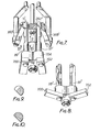
- Figs. 7 and 8 show an embodiment of the cam and follower arm structure of the invention wherein the cams are rotatably mounted so that the slotted surfaces of the cam can be readily disengaged from the cam follower lever arms permitting the plunger to be moved in or out more readily. It is advantageous to have a.cam which may be rotated rather than unfastened. Such a feature would greatly facilitate and speed up resetting of the plunger and placement and removal of the tubing in or from the arcuate slots in the tube guides 31 and 32. In Figs. -7 and 8 parts similar to those previously described are correspondingly numbered and primed.
- the cams 39' and 51' in Figs. 7 and 8 are generally rod-shaped and are rotatably mounted on end piece 704. Cross-sectional views of a typical cam 39' at various locations along cam 39' are shown in Figs. 9 and 10. Handles 700 and 702 are attached to one end of each rod-shaped cam. Thus, when it is desired to release the cam follower arms 350' or 365' from engagement in a slot in the cam surface S' it is only required to rotate the handles into the positions shown in Fig. 8.
Landscapes
- Centrifugal Separators (AREA)
- External Artificial Organs (AREA)
- Medicines Containing Material From Animals Or Micro-Organisms (AREA)
Priority Applications (1)
| Application Number | Priority Date | Filing Date | Title |
|---|---|---|---|
| AT82303591T ATE31388T1 (de) | 1981-07-09 | 1982-07-08 | Zentrifugen-apparat. |
Applications Claiming Priority (2)
| Application Number | Priority Date | Filing Date | Title |
|---|---|---|---|
| US06/281,650 US4417884A (en) | 1981-07-09 | 1981-07-09 | Centrifuge timer clamp |
| US281650 | 1981-07-09 |
Publications (3)
| Publication Number | Publication Date |
|---|---|
| EP0070156A2 true EP0070156A2 (de) | 1983-01-19 |
| EP0070156A3 EP0070156A3 (en) | 1984-06-20 |
| EP0070156B1 EP0070156B1 (de) | 1987-12-16 |
Family
ID=23078217
Family Applications (1)
| Application Number | Title | Priority Date | Filing Date |
|---|---|---|---|
| EP82303591A Expired EP0070156B1 (de) | 1981-07-09 | 1982-07-08 | Zentrifugen-Apparat |
Country Status (8)
| Country | Link |
|---|---|
| US (1) | US4417884A (de) |
| EP (1) | EP0070156B1 (de) |
| JP (1) | JPS5817857A (de) |
| AT (1) | ATE31388T1 (de) |
| AU (1) | AU8575082A (de) |
| DE (1) | DE3277833D1 (de) |
| DK (1) | DK306682A (de) |
| ES (1) | ES8403728A1 (de) |
Families Citing this family (18)
| Publication number | Priority date | Publication date | Assignee | Title |
|---|---|---|---|---|
| US4694861A (en) * | 1986-12-22 | 1987-09-22 | Beckman Instruments, Inc. | Rotary pinch valve |
| US4806252A (en) * | 1987-01-30 | 1989-02-21 | Baxter International Inc. | Plasma collection set and method |
| US6780333B1 (en) | 1987-01-30 | 2004-08-24 | Baxter International Inc. | Centrifugation pheresis method |
| US5104526A (en) * | 1987-01-30 | 1992-04-14 | Baxter International Inc. | Centrifugation system having an interface detection system |
| US4940543A (en) * | 1987-01-30 | 1990-07-10 | Baxter International Inc. | Plasma collection set |
| US5076911A (en) * | 1987-01-30 | 1991-12-31 | Baxter International Inc. | Centrifugation chamber having an interface detection surface |
| US4834890A (en) * | 1987-01-30 | 1989-05-30 | Baxter International Inc. | Centrifugation pheresis system |
| US6773389B2 (en) | 2000-11-02 | 2004-08-10 | Gambro Inc | Fluid separation devices, systems and/or methods using a fluid pressure driven and/or balanced configuration |
| US20030040835A1 (en) * | 2001-04-28 | 2003-02-27 | Baxter International Inc. | A system and method for managing inventory of blood component collection soft goods in a blood component collection facility |
| US7186230B2 (en) * | 2002-03-04 | 2007-03-06 | Therakos, Inc | Method and apparatus for the continuous separation of biological fluids into components |
| US7211037B2 (en) | 2002-03-04 | 2007-05-01 | Therakos, Inc. | Apparatus for the continuous separation of biological fluids into components and method of using same |
| US7479123B2 (en) | 2002-03-04 | 2009-01-20 | Therakos, Inc. | Method for collecting a desired blood component and performing a photopheresis treatment |
| ITMI20031715A1 (it) * | 2003-09-05 | 2005-03-06 | Dideco Spa | Dispositivo di comando nella raccolta differenziata dei |
| US7060018B2 (en) * | 2003-09-11 | 2006-06-13 | Cobe Cardiovascular, Inc. | Centrifuge apparatus for processing blood |
| US7476209B2 (en) | 2004-12-21 | 2009-01-13 | Therakos, Inc. | Method and apparatus for collecting a blood component and performing a photopheresis treatment |
| EP2206527B1 (de) * | 2006-09-06 | 2016-01-27 | Terumo BCT, Inc. | Vorrichtung und Verfahren zur Trennung einer Flüssigverbindung in mindestens zwei Komponenten |
| US7806820B2 (en) * | 2007-05-02 | 2010-10-05 | Gary Wayne Howell | Automatic balancing device and system for centrifuge rotors |
| US8986238B2 (en) | 2012-08-15 | 2015-03-24 | Cyclone Medtech, Inc. | Systems and methods for salvaging red blood cells for autotransfusion |
Family Cites Families (11)
| Publication number | Priority date | Publication date | Assignee | Title |
|---|---|---|---|---|
| FR499880A (fr) * | 1919-05-21 | 1920-02-25 | Georges Rocques | Minuterie à huile |
| US3190546A (en) * | 1959-03-27 | 1965-06-22 | Raccuglia Giovanni | Method and apparatus for separating liquid mixtures |
| US3421414A (en) * | 1966-03-15 | 1969-01-14 | Ingersoll Rand Co | Flyweight |
| US3480207A (en) * | 1966-06-15 | 1969-11-25 | Karl Strohmaier | Centrifuge with efficiency measuring device |
| SE332906B (de) * | 1969-08-11 | 1971-02-22 | Aga Ab | |
| US3674197A (en) * | 1970-09-08 | 1972-07-04 | Sorvall Inc Ivan | Washing means for flexible bags in split enclosures |
| US3907504A (en) * | 1973-04-06 | 1975-09-23 | Gen Electric | Blood oxygenation system including automatic means for stabilizing the flow rate of blood therethrough |
| JPS50107565A (de) * | 1974-01-29 | 1975-08-25 | ||
| US4061142A (en) * | 1976-06-16 | 1977-12-06 | Sandoz, Inc. | Apparatus for controlling blood flow |
| US4146172A (en) * | 1977-10-18 | 1979-03-27 | Baxter Travenol Laboratories, Inc. | Centrifugal liquid processing system |
| US4244513A (en) * | 1978-09-15 | 1981-01-13 | Coulter Corporation | Centrifuge unit |
-
1981
- 1981-07-09 US US06/281,650 patent/US4417884A/en not_active Expired - Fee Related
-
1982
- 1982-07-08 AU AU85750/82A patent/AU8575082A/en not_active Abandoned
- 1982-07-08 EP EP82303591A patent/EP0070156B1/de not_active Expired
- 1982-07-08 DE DE8282303591T patent/DE3277833D1/de not_active Expired
- 1982-07-08 AT AT82303591T patent/ATE31388T1/de not_active IP Right Cessation
- 1982-07-08 DK DK306682A patent/DK306682A/da not_active Application Discontinuation
- 1982-07-08 ES ES513814A patent/ES8403728A1/es not_active Expired
- 1982-07-09 JP JP57119696A patent/JPS5817857A/ja active Pending
Also Published As
| Publication number | Publication date |
|---|---|
| EP0070156A3 (en) | 1984-06-20 |
| ES513814A0 (es) | 1983-12-01 |
| AU8575082A (en) | 1983-01-13 |
| US4417884A (en) | 1983-11-29 |
| DE3277833D1 (en) | 1988-01-28 |
| EP0070156B1 (de) | 1987-12-16 |
| ATE31388T1 (de) | 1988-01-15 |
| JPS5817857A (ja) | 1983-02-02 |
| ES8403728A1 (es) | 1984-04-16 |
| DK306682A (da) | 1983-01-26 |
Similar Documents
| Publication | Publication Date | Title |
|---|---|---|
| EP0070156B1 (de) | Zentrifugen-Apparat | |
| US4425235A (en) | Blood collection device with phase partitioning means | |
| RU2722007C2 (ru) | Устройство для приготовления напитка центрифугированием, содержащее клапан в средстве для слива напитка | |
| US4268393A (en) | Apparatus for centrifugal separation of platelet-rich plasma | |
| US3469572A (en) | Apparatus for taking multiple fluid samples | |
| EP2206527B1 (de) | Vorrichtung und Verfahren zur Trennung einer Flüssigverbindung in mindestens zwei Komponenten | |
| EP0686064A1 (de) | Handpipette mit kolbengeschwindigkeitsregler, ruhestellungverriegelung und auslösevorrichtung | |
| EP0409445A1 (de) | Türschliesser | |
| US5529738A (en) | Method of making a plunger cap | |
| KR20010049172A (ko) | 혈액 채취 방법 및 장치 | |
| WO2001003798A9 (en) | Automated blood component separation system | |
| DE4109978A1 (de) | Temperaturfuehlende ventilatorkupplungseinrichtung des fluessigkeitstyps | |
| US2679807A (en) | Pumping device | |
| US3459263A (en) | Fluid sampling device | |
| US4127231A (en) | Support arm for centrifugal liquid processing apparatus | |
| JPS6483964A (en) | Controlling device and method of transmission for car | |
| US4869458A (en) | Liquid distribution valve | |
| CN110944754B (zh) | 用于将生物流体分离成其组分的系统及其使用 | |
| JPH03195685A (ja) | 液圧式エレベータ用制御弁 | |
| US3371522A (en) | Apparatus for measuring viscosity | |
| GB2158148A (en) | Door closer | |
| JPS62278317A (ja) | ユニバ−サルジヨイントにおける潤滑装置 | |
| EP0780613B1 (de) | Hydraulisches Absperrventil | |
| JPH022039B2 (de) | ||
| EP0390380A3 (de) | Steuergerät für Flüssigkeitsströmung |
Legal Events
| Date | Code | Title | Description |
|---|---|---|---|
| PUAI | Public reference made under article 153(3) epc to a published international application that has entered the european phase |
Free format text: ORIGINAL CODE: 0009012 |
|
| AK | Designated contracting states |
Designated state(s): AT CH DE FR GB IT LI NL SE |
|
| PUAL | Search report despatched |
Free format text: ORIGINAL CODE: 0009013 |
|
| AK | Designated contracting states |
Designated state(s): AT CH DE FR GB IT LI NL SE |
|
| 17P | Request for examination filed |
Effective date: 19841130 |
|
| 17Q | First examination report despatched |
Effective date: 19860210 |
|
| GRAA | (expected) grant |
Free format text: ORIGINAL CODE: 0009210 |
|
| RAP1 | Party data changed (applicant data changed or rights of an application transferred) |
Owner name: HAEMONETICS CORPORATION(A MASSACHUSETTS CORPORATIO |
|
| AK | Designated contracting states |
Kind code of ref document: B1 Designated state(s): AT CH DE FR GB IT LI NL SE |
|
| PG25 | Lapsed in a contracting state [announced via postgrant information from national office to epo] |
Ref country code: NL Effective date: 19871216 Ref country code: LI Effective date: 19871216 Ref country code: IT Free format text: LAPSE BECAUSE OF FAILURE TO SUBMIT A TRANSLATION OF THE DESCRIPTION OR TO PAY THE FEE WITHIN THE PRESCRIBED TIME-LIMIT;WARNING: LAPSES OF ITALIAN PATENTS WITH EFFECTIVE DATE BEFORE 2007 MAY HAVE OCCURRED AT ANY TIME BEFORE 2007. THE CORRECT EFFECTIVE DATE MAY BE DIFFERENT FROM THE ONE RECORDED. Effective date: 19871216 Ref country code: CH Effective date: 19871216 Ref country code: AT Effective date: 19871216 |
|
| REF | Corresponds to: |
Ref document number: 31388 Country of ref document: AT Date of ref document: 19880115 Kind code of ref document: T |
|
| PG25 | Lapsed in a contracting state [announced via postgrant information from national office to epo] |
Ref country code: SE Effective date: 19871231 |
|
| ET | Fr: translation filed | ||
| REF | Corresponds to: |
Ref document number: 3277833 Country of ref document: DE Date of ref document: 19880128 |
|
| REG | Reference to a national code |
Ref country code: CH Ref legal event code: PL |
|
| NLV1 | Nl: lapsed or annulled due to failure to fulfill the requirements of art. 29p and 29m of the patents act | ||
| PG25 | Lapsed in a contracting state [announced via postgrant information from national office to epo] |
Ref country code: GB Effective date: 19880708 |
|
| PLBE | No opposition filed within time limit |
Free format text: ORIGINAL CODE: 0009261 |
|
| STAA | Information on the status of an ep patent application or granted ep patent |
Free format text: STATUS: NO OPPOSITION FILED WITHIN TIME LIMIT |
|
| 26N | No opposition filed | ||
| GBPC | Gb: european patent ceased through non-payment of renewal fee | ||
| PG25 | Lapsed in a contracting state [announced via postgrant information from national office to epo] |
Ref country code: FR Free format text: LAPSE BECAUSE OF NON-PAYMENT OF DUE FEES Effective date: 19890331 |
|
| PG25 | Lapsed in a contracting state [announced via postgrant information from national office to epo] |
Ref country code: DE Effective date: 19890401 |
|
| REG | Reference to a national code |
Ref country code: FR Ref legal event code: ST |