EP0070161A2 - Dispositif et méthode pour la détermination adaptive d'un niveau de seuil - Google Patents
Dispositif et méthode pour la détermination adaptive d'un niveau de seuil Download PDFInfo
- Publication number
- EP0070161A2 EP0070161A2 EP82303601A EP82303601A EP0070161A2 EP 0070161 A2 EP0070161 A2 EP 0070161A2 EP 82303601 A EP82303601 A EP 82303601A EP 82303601 A EP82303601 A EP 82303601A EP 0070161 A2 EP0070161 A2 EP 0070161A2
- Authority
- EP
- European Patent Office
- Prior art keywords
- threshold
- pixels
- pixel
- minimum
- maximum
- Prior art date
- Legal status (The legal status is an assumption and is not a legal conclusion. Google has not performed a legal analysis and makes no representation as to the accuracy of the status listed.)
- Granted
Links
- 238000000034 method Methods 0.000 title claims abstract description 12
- 230000003044 adaptive effect Effects 0.000 title abstract description 14
- 239000000872 buffer Substances 0.000 claims description 16
- 230000003139 buffering effect Effects 0.000 claims description 4
- 238000012545 processing Methods 0.000 abstract description 2
- 238000003491 array Methods 0.000 description 7
- 238000001514 detection method Methods 0.000 description 6
- 238000012216 screening Methods 0.000 description 3
- 239000000976 ink Substances 0.000 description 2
- 230000002159 abnormal effect Effects 0.000 description 1
- 230000004308 accommodation Effects 0.000 description 1
- 238000006243 chemical reaction Methods 0.000 description 1
- 238000012937 correction Methods 0.000 description 1
- 230000001934 delay Effects 0.000 description 1
- 230000002250 progressing effect Effects 0.000 description 1
- 238000013519 translation Methods 0.000 description 1
- 230000014616 translation Effects 0.000 description 1
Images

Classifications
-
- H—ELECTRICITY
- H04—ELECTRIC COMMUNICATION TECHNIQUE
- H04N—PICTORIAL COMMUNICATION, e.g. TELEVISION
- H04N1/00—Scanning, transmission or reproduction of documents or the like, e.g. facsimile transmission; Details thereof
- H04N1/40—Picture signal circuits
- H04N1/403—Discrimination between the two tones in the picture signal of a two-tone original
Definitions
- This invention relates to a method and apparatus for thresholding image pixels, and more particularly to an improved method and apparatus for adaptively thresholding image pixels in response to changes in image content.
- the document original comprises line copy, i.e. a typed sheet
- variations in input line density may require variations in threshold. Otherwise, image portions may be missed as for example where the line density is below the existing threshold level. In that case, the line image is consigned to background and therefore lost.
- variations in background density may require variations in thresholds. Otherwise, areas that should be identified as background are instead identified as image areas. Typically this occurs when the background area rises above the threshold level as may occur when the document original or a portion thereof has a colored background.
- Combinations of the aforementioned, i.e. variations in line density and in background density also demonstrate the need for adjusting threshold levels in accordance with the image content of the document original.
- threshold variation is helpful when one is seeking to reproduce the halftone without rescreening.
- macro adaptive thresholding which is a once per page correction for the environment, corrects for background variations and line density variations.
- an optimal single level threshold may not be sufficient as noted earlier.
- the simultaneous enhancement of detectability for small "white” and "black” detail is not enabled by a one-per-page, macro adaptive, threshold.
- micro adaptive thresholding the conversion from multivalued to binary valued picture elements or pixels is a function of regional properties of the image. Microadaptation may correct for line density and background as well as facilitate enhanced detection of MTF degraded detail imagery. Furthermore, images with regions of various densities of lines may be reproduced with regionally independent thresholds.
- micro adaptive thresholding logic is in general a more complex function than the simple threshold function. Simple thresholding is a point process while micro adapative thresholding is a function of the neighborhood around the pixel being converted to a binary level.
- One and two pass processing may also be thought of where a . prescan of an image is the first step in a macro adaptive strategy.
- One may then use a pixel graylevel histogram to select the threshold for the entire page. This results in a two pass scan of the image or a grayscale buffering of the entire image. Either method is relatively expensive. Furthermore, average statistics such as from a graylevel histogram may be very misleading to threshold selection logic.
- a one pass macro adaptive threshold function relies in general on the image margins and perhaps on the first "black" information to set the threshold value for the remainder of the page.
- Micro adaptive threshold logic may utilize large contexts to define the binary output value of a single pixel. Although it is possible to develop a two pass micro adaptive algorithm, in general only one pass is required. The expense is incurred by the need to buffer and manipulate the context around the pixel to be converted to a binary value.
- the present invention relates to a method of determining the optimum threshold for thresholding image pixels, characterised by the steps of buffering a block of image pixels in a stream of image pixels, at least one of the pixels in the block of pixels comprising the pixel to be thresholded; identifying maximum and minimum pixels in the block of pixels; differencing the maximum and minimum pixels from one another to provide a difference signal; multiplying the difference signal by a predetermined constant representing a desired change in threshold level to provide a base threshold; and differencing the base threshold from the maximum pixel to provide the optimum threshold.
- the invention further relates to an apparatus for adaptively thresholding image pixels, characterised by: buffer means for storing a plurality of successive ones of the pixels including the pixel to be thresholded; means for identifying the maximum pixel in the plurality of pixels; means for identifying the minimum pixel in the plurality of pixels; first subtractor means for subtracting the output of the maximum pixel identifying means from said minimum pixel identifying means; multiplier means for multiplying the output of the first subtractor means by a predetermined constant representing a desired change in threshold level; and second subtractor means for subtracting the output of the multiplier means from the maximum pixel identifying means to provide a threshold for use in thresholding the one pixel.
- pixel refers to a picture element which essentially comprises a signal, the voltage level of which is representative of image graylevel.
- a voltage level of zero may be considered as representing black while a voltage level of 255 millivolts (m.v.) may be considered as representing white.
- Voltage levels between zero and 255 m.v. represent different shades of gray from the darkest gray at 1 millivolt and progressing upwardly to the lightest gray at 254 millivolts.
- the image pixels may be derived from any suitable source as for example a raster input scanner of the type employing one or more linear arrays, for example CCD's, arranged to scan the image on a document original line by line. For this purpose, relative movement as by means of a document transport is established between the original being scanned and the array or arrays.
- the image pixels produced by the array or arrays which due to the inherent operating characteristics of arrays of this type are in bursts of one line each, are typically processed by thresholding or screening. For thresholding, the image pixels are compared, i.e. thresholded against a preset signal or threshold level which effectively converts the analog pixel signals output by the array or arrays to binary level pixel signals.
- a threshold of 128 millivolts may be envisioned. With the use of a comparator circuit, pixels below 128 millivolts are classified as black image areas while pixels equal to or above 128 millivolts are classified as white or background image areas. Screening is similar except that multiple ones of the image pixels are compared or thresholded against a corresponding number of selected threshold levels.
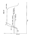
- FIG. 1 of the drawings there is shown a plot of a typical image line, identified by the numeral 10, as derived from an original having a line copy image, i.e. a typed page.
- the normal image line A-B rises above the nominal threshold level and hence is identified by the ' thresholder as image data. Areas below the threshold level are of course identified as non-image or background areas.
- abnormal image lines such as low density lines shown at C-D, may not rise to the threshold level and when processed are not identified as image areas but rather are classified erroneously as non-image or background areas.
- the present invention seeks to accommodate for this inherent inability in threshold systems, and screening systems as well, to ' detect or compensate for marginal image and background areas.
- the present invention as will appear provides a threshold level which adapts or changes in accommodation of variations in image and/or background artifacts.
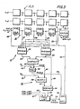
- Thresholder 11 includes a buffer array 12 comprised of a plurality of one pixel delay buffers 13-1, 13-2, 13-3, 13-n, for imposing a succession of one pixel delays on the stream of image pixels input thereto through line 14 from a suitable source (not shown).
- Output line 15 couples the output of the last buffer 13-n in the buffer array 12 to one input of a comparator or thresholding circuit 20.
- Pixel input line 14 is tapped by line 22 which is in turn coupled to one input terminal of minimum and maximum pixel level detection circuits 24, 26, respectively.
- Lines 27, 28, 29, 30 couple the output side of the several one pixel delay buffers 13-1, 13-2, 13-3, 13-n comprising buffer array 12 to the input terminals of minimum and maximum pixel detection circuits 24, 26.
- Minimum and maximum pixel level detection circuits 24, 26 comprise any suitable circuitry capable of identifying the minimum and maximum pixels in the block of pixels across delay buffer 12. Circuits 24, 26 for example may comprise a series of comparator circuits arranged to compare the various signal inputs thereto for the purpose of identifying the smallest (i.e. the minimum) and largest (i.e. the maximum) pixels.
- Lines 34, 35 couple the output terminals of minimum and maximum pixel level detector circuits to differencing circuit herein a subtractor 38.
- Subtractor 38 which comprises any suitable circuit for subtracting or differencing two signal inputs, outputs a difference signal (RANGE) via line 40 to - event detection or comparator circuit 42 and via line 44 to multiplier circuit 46.
- Comparator circuit 42 which controls enabling of new threshold control gate 50, compares the difference signal output by subtractor 38 with a preset value 91, representing a minimum slope or rate of change in image background level, input through line 47.
- One suitable value for 01 is 30°.
- the control signal output of comparator 42, which controls enabling of new threshold control gate 50 is fed to the enabling input of gate 50 through line 48.
- a threshold determining circuit 45 includes a multiplier 46, which comprises any suitable multiplier circuit, to multiply the difference signal output of subtractor 38 by a preset weighting factor input through line 52.
- Weighting factor Q2 is a value, which may be experimentally determined, representing the amount of change in threshold level for a given event. A preferred value of 02 is 40%.
- the output of multiplier 46 is coupled by line 55 to one input of subtractor 56.
- a second input of subtractor 56 is coupled by line 58 to the output of maximum pixel level detection circuit 26.
- Subtractor 56 subtracts or differences the maximum pixel level output of circuit 26 from the maximum background signal output of multiplier 46 to provide a new threshold.
- the new threshold output by subtractor 56 is fed through line 60 to threshold level limiting circuit 65.
- Preset high and low threshold level limiting voltages are input to circuit 65 through lines 66, 67 respectively.
- Threshold level limiting circuit 65 which comprises any suitable comparator circuit, serves to compare the new threshold output by subtractor 56 with the preset high and low threshold level limits. Where the new threshold is greater than or less than one of the preset high and low threshold level limits, the new threshold is reduced or raised as appropriate to the preset high or low threshold level limits.
- threshold level limiting circuit 65 is fed through line 70 to the input of threshold control gate 50.
- the output of gate 50 is coupled to a second input terminal of threshold circuit 20 through line 72.
- Lines of image pixels are clocked pixel by pixel through buffer array 12 by suitable pixel clock signals, it being understood that with each clock pulse, the pixels advance one step from one pixel delay buffer to the next.
- the instantaneous pixel levels in buffer 12 are jointly input to minimum and maximum pixel detector circuits 24, 26 respectively, . where the current minimum and maximum pixels are identified.
- the minimum and maximum pixels Identified by circuits 24, 26 are input to subtractor 38 where the pixels are differenced to provide a difference (i.e. RANGE) signal.
- the difference signal output by subtractor 38 is fed to event comparator 42 to determine if the new threshold (which is calculated in any event) will be used, and to multiplier 46 of threshold determining circuit 45 where the new threshold is calculated.
- comparator 42 compares the difference signal with a predetermined constant, 91 representing a minimum change in background density. Where the difference signal is above the constant, indicating that the rate of change in the background image is greater than the predetermined minimum representated by the constant 01, a signal from comparator 42 enables threshold control gate 50 to apply the new threshold output by threshold determining circuit 45 to thresholding circuit 20. Where the rate of change in image background is less than the predetermined minimum, control gate 50 is not enabled and application of the new threshold to thresholding circuit 20 is precluded.
- a new threshold is determined based upon the content of delay buffer 12 by threshold determining circuit 45.
- the difference signal (RANGE) output by subtractor 38 is fed to multiplier circuit 46 of circuit 45 where the difference signal is multiplied by the weighting factor 92 representing the amount of change in threshold for a given event.
- the threshold signal output by multiplier 46 is fed to subtractor 56 where the threshold signal is subtracted from the maximum pixel signal output by maximum pixel detector circuit 26 to provide a new threshold.
- the new threshold output by subtractor 56 is compared with preset maximum and minimum threshold limits and reduced or increased as required to bring the new threshold to a level no greater than or less than the preset threshold limits by comparator circuit 65.
- the new threshold is output to threshold control gate 50 for application to thresholding circuit 20 should control gate 50 be enabled as described heretofore.
Landscapes
- Engineering & Computer Science (AREA)
- Multimedia (AREA)
- Signal Processing (AREA)
- Facsimile Image Signal Circuits (AREA)
- Image Processing (AREA)
- Character Input (AREA)
- Image Input (AREA)
Applications Claiming Priority (2)
| Application Number | Priority Date | Filing Date | Title |
|---|---|---|---|
| US281816 | 1981-07-09 | ||
| US06/281,816 US4442544A (en) | 1981-07-09 | 1981-07-09 | Adaptive thresholder |
Publications (3)
| Publication Number | Publication Date |
|---|---|
| EP0070161A2 true EP0070161A2 (fr) | 1983-01-19 |
| EP0070161A3 EP0070161A3 (en) | 1983-03-23 |
| EP0070161B1 EP0070161B1 (fr) | 1985-10-09 |
Family
ID=23078915
Family Applications (1)
| Application Number | Title | Priority Date | Filing Date |
|---|---|---|---|
| EP82303601A Expired EP0070161B1 (fr) | 1981-07-09 | 1982-07-09 | Dispositif et méthode pour la détermination adaptive d'un niveau de seuil |
Country Status (5)
| Country | Link |
|---|---|
| US (1) | US4442544A (fr) |
| EP (1) | EP0070161B1 (fr) |
| JP (1) | JPH0620242B2 (fr) |
| CA (1) | CA1180102A (fr) |
| DE (1) | DE3266810D1 (fr) |
Cited By (18)
| Publication number | Priority date | Publication date | Assignee | Title |
|---|---|---|---|---|
| DE3433493A1 (de) * | 1983-09-12 | 1985-04-04 | Ricoh Co., Ltd., Tokio/Tokyo | System zur digitalisierung von bildsignalen |
| EP0106316A3 (en) * | 1982-10-19 | 1986-02-12 | Siemens Aktiengesellschaft | Method and arrangement for detecting amplitude changes in the output signal of an optical sensor |
| DE3629793A1 (de) * | 1986-09-02 | 1988-03-03 | Agfa Gevaert Ag | Verfahren zum punkt- und zeilenweisen kopieren einer mehrfarbigen kopiervorlage und vorrichtung zur durchfuehrung dieses verfahrens |
| FR2604582A1 (fr) * | 1986-09-30 | 1988-04-01 | Bertin & Cie | Procede pour transformer une image initiale de type video a multiples niveaux de gris en une image binaire |
| EP0160363A3 (en) * | 1984-04-28 | 1988-09-14 | Kabushiki Kaisha Toshiba | Binarizing system of picture image signals |
| WO1988007798A1 (fr) * | 1987-03-23 | 1988-10-06 | Eastman Kodak Company | Appareil permettant d'etablir des references de fond |
| WO1990006653A1 (fr) * | 1988-12-02 | 1990-06-14 | Image Processing Technologies, Inc. | Procede et appareil pour numeriser une image |
| US5109436A (en) * | 1989-03-28 | 1992-04-28 | Kabushiki Kaisha Toshiba | Image data processing system with adaptive binary quantization |
| EP0424854A3 (en) * | 1989-10-23 | 1993-02-10 | Sharp Kabushiki Kaisha | Binary image processing apparatus |
| US5268773A (en) * | 1990-03-30 | 1993-12-07 | Samsung Electronics Co., Ltd. | Document image signal processor having an adaptive threshold |
| EP0549255A3 (fr) * | 1991-12-23 | 1994-04-06 | Xerox Corp | |
| EP0531923A3 (fr) * | 1991-09-10 | 1994-10-12 | Eastman Kodak Co | Méthode et appareil de quantification de niveaux de gris. |
| WO1994023531A1 (fr) * | 1993-04-01 | 1994-10-13 | Image Processing Technologies, Inc. | Procede et dispositif d'analyse de donnees d'image dans un signal numerique en provenance d'un document balaye |
| EP0581971A4 (fr) * | 1992-02-25 | 1995-04-19 | Pfu Ltd | Numeriseur d'image. |
| US5625718A (en) * | 1992-02-25 | 1997-04-29 | Pfu Limited | White level setting system for an image scanner |
| EP0740456A3 (fr) * | 1992-07-23 | 1998-04-01 | Fuji Xerox Co., Ltd. | Dispositif de traitement d'images capable de déterminer correctement la densité d'une portion du fond |
| US5915049A (en) * | 1992-02-25 | 1999-06-22 | Pfu Limited | Binarization system for an image scanner |
| KR100492529B1 (ko) * | 1997-12-23 | 2005-10-26 | 엘지전자 주식회사 | 적응 단순 이진화 영상처리방법 |
Families Citing this family (32)
| Publication number | Priority date | Publication date | Assignee | Title |
|---|---|---|---|---|
| GB2103449B (en) * | 1981-06-29 | 1985-05-30 | Nippon Telegraph & Telephone | Method and apparatus for gray level signal processing |
| US4491963A (en) * | 1982-08-17 | 1985-01-01 | Pitney Bowes Inc. | Correction of imaging imperfections |
| US4691239A (en) * | 1982-12-23 | 1987-09-01 | Nelson Martin N | Dynamic video system and method |
| US4747148A (en) * | 1983-04-11 | 1988-05-24 | Kabushiki Kaisha Komatsu Seisakusho | Method of identifying objects |
| US4972501A (en) * | 1984-03-01 | 1990-11-20 | Canon Kabushiki Kaisha | Image processing apparatus |
| JPS60230768A (ja) * | 1984-04-28 | 1985-11-16 | Toshiba Corp | 画像信号の二値化方式 |
| GB8521019D0 (en) * | 1985-08-22 | 1986-10-01 | Rank Pullin Controls Ltd | Imaging apparatus |
| JPH0719275B2 (ja) * | 1986-07-08 | 1995-03-06 | 住友電気工業株式会社 | 二値化回路 |
| US4853795A (en) * | 1987-07-24 | 1989-08-01 | Eastman Kodak Company | Forward look ahead techniques for tracking background and noise levels in scanned video images |
| US4868670A (en) * | 1987-07-24 | 1989-09-19 | Eastman Kodak Company | Apparatus and method for improving the compressibility of an enhanced image through use of a momentarily varying threshold level |
| US4982294A (en) * | 1987-07-24 | 1991-01-01 | Eastman Kodak Company | Apparatus for enhancing and thresholding scanned microfilm images and methods for use therein |
| US4949389A (en) * | 1987-10-09 | 1990-08-14 | The United States Of America As Represented By The United States Department Of Energy | Optical ranked-order filtering using threshold decomposition |
| US4897803A (en) * | 1987-11-23 | 1990-01-30 | Xerox Corporation | Address token based image manipulation |
| DE3800820A1 (de) * | 1988-01-14 | 1989-07-27 | Bosch Gmbh Robert | Verfahren zur rechnergestuetzten darstellung zu untersuchender probe-graphiken in form von punktmatrixdarstellungen mit zwei unterschiedlichen soll-helligkeitswerten unter vergleich mit einer abgespeicherten muster-graphik |
| US5060284A (en) * | 1990-03-23 | 1991-10-22 | Eastman Kodak Company | Adaptive error diffusion thresholding for document images |
| US5377282A (en) * | 1991-09-19 | 1994-12-27 | International Business Machines Corporation | Optical inspection system utilizing dynamic analog-to-digital thresholding |
| US5337373A (en) * | 1991-10-24 | 1994-08-09 | International Business Machines Corporation | Automatic threshold generation technique |
| US10361802B1 (en) | 1999-02-01 | 2019-07-23 | Blanding Hovenweep, Llc | Adaptive pattern recognition based control system and method |
| US8352400B2 (en) | 1991-12-23 | 2013-01-08 | Hoffberg Steven M | Adaptive pattern recognition based controller apparatus and method and human-factored interface therefore |
| WO1994017491A1 (fr) * | 1993-01-27 | 1994-08-04 | United Parcel Service Of America, Inc. | Procede et appareil de seuillage d'images |
| US5617489A (en) * | 1993-08-04 | 1997-04-01 | Richard S. Adachi | Optical adaptive thresholder for converting analog signals to binary signals |
| US5608814A (en) * | 1993-08-26 | 1997-03-04 | General Electric Company | Method of dynamic thresholding for flaw detection in ultrasonic C-scan images |
| US8364136B2 (en) | 1999-02-01 | 2013-01-29 | Steven M Hoffberg | Mobile system, a method of operating mobile system and a non-transitory computer readable medium for a programmable control of a mobile system |
| US7966078B2 (en) | 1999-02-01 | 2011-06-21 | Steven Hoffberg | Network media appliance system and method |
| US7092035B1 (en) * | 2001-07-09 | 2006-08-15 | Lsi Logic Corporation | Block move engine with scaling and/or filtering for video or graphics |
| US6842541B2 (en) * | 2001-10-31 | 2005-01-11 | Xerox Corporation | Adaptive color super resolution thresholding |
| US7480420B2 (en) * | 2002-09-04 | 2009-01-20 | Transpacific Ip, Ltd. | Method for recognizing abnormal image |
| JP2006279709A (ja) * | 2005-03-30 | 2006-10-12 | Toshiba Corp | 情報処理装置および画像処理方法 |
| CA2626841A1 (fr) * | 2005-11-23 | 2007-05-31 | Object Video, Inc. | Estimation de la densite d'objets dans des flux video |
| US7995829B2 (en) * | 2007-08-01 | 2011-08-09 | General Electric Company | Method and apparatus for inspecting components |
| EP2534475A4 (fr) * | 2010-02-08 | 2017-04-19 | Canon Kabushiki Kaisha | Procédé et appareil de réduction du bruit dans signal de masse |
| US10475189B2 (en) | 2017-12-11 | 2019-11-12 | Adobe Inc. | Content aware, spatially adaptive automated thresholding of images |
Family Cites Families (16)
| Publication number | Priority date | Publication date | Assignee | Title |
|---|---|---|---|---|
| US3509533A (en) * | 1965-06-07 | 1970-04-28 | Recognition Equipment Inc | Digital-analog optical character recognition |
| DE1247051B (de) * | 1965-06-18 | 1967-08-10 | Siemens Ag | Schaltungsanordnung zum Ausgleich von Kontrastaenderungen bei der Digitalisierung von Video-Signalen |
| US3599151A (en) * | 1969-12-29 | 1971-08-10 | Ibm | Character recognition photosensing apparatus having a threshold comparator circuit |
| DE2214658C3 (de) * | 1972-03-25 | 1974-12-19 | Licentia Patent-Verwaltungs-Gmbh, 6000 Frankfurt | Schaltung zur Schwellenwertbüdung |
| US3852714A (en) * | 1972-06-22 | 1974-12-03 | Eocom Corp | Adaptive imaging system |
| US3842200A (en) * | 1972-10-19 | 1974-10-15 | Scanner | Contrast processing of video signals with self-adjusting reference |
| US4051536A (en) * | 1975-03-14 | 1977-09-27 | Xerox Corporation | Electronic halftone imaging system |
| JPS5218132A (en) * | 1975-08-01 | 1977-02-10 | Hitachi Ltd | Binary circuit |
| JPS5313822A (en) * | 1976-07-23 | 1978-02-07 | Sharp Corp | Video information reader |
| US4159432A (en) * | 1977-11-30 | 1979-06-26 | International Business Machines Corporation | Analog signal manipulation using charge transfer techniques |
| DE2800759C3 (de) * | 1978-01-09 | 1984-08-23 | Dr.-Ing. Rudolf Hell Gmbh, 2300 Kiel | Verfahren zur Umwandlung eines Videosignals in ein Zwei-Pegel-Signal |
| FR2425780A1 (fr) * | 1978-05-12 | 1979-12-07 | Cit Alcatel | Convertisseur auto-adaptatif en tout ou rien d'un signal d'analyse d'image |
| JPS5534704A (en) * | 1978-08-31 | 1980-03-11 | Hajime Sangyo Kk | Threshold setting circuit |
| FR2435871A1 (fr) * | 1978-09-08 | 1980-04-04 | Thomson Csf | Dispositif a seuil permettant de distinguer le blanc du noir sur un document, et emetteur de telecopie comportant un tel dispositif |
| FR2437125A1 (fr) * | 1978-09-21 | 1980-04-18 | Cit Alcatel | Dispositif de traitement d'un signal d'analyse d'image |
| JPS566523A (en) * | 1979-06-29 | 1981-01-23 | Hitachi Ltd | Video binary coding system |
-
1981
- 1981-07-09 US US06/281,816 patent/US4442544A/en not_active Expired - Lifetime
-
1982
- 1982-06-22 CA CA000405755A patent/CA1180102A/fr not_active Expired
- 1982-07-02 JP JP57115311A patent/JPH0620242B2/ja not_active Expired - Lifetime
- 1982-07-09 EP EP82303601A patent/EP0070161B1/fr not_active Expired
- 1982-07-09 DE DE8282303601T patent/DE3266810D1/de not_active Expired
Cited By (23)
| Publication number | Priority date | Publication date | Assignee | Title |
|---|---|---|---|---|
| EP0106316A3 (en) * | 1982-10-19 | 1986-02-12 | Siemens Aktiengesellschaft | Method and arrangement for detecting amplitude changes in the output signal of an optical sensor |
| DE3433493A1 (de) * | 1983-09-12 | 1985-04-04 | Ricoh Co., Ltd., Tokio/Tokyo | System zur digitalisierung von bildsignalen |
| EP0160363A3 (en) * | 1984-04-28 | 1988-09-14 | Kabushiki Kaisha Toshiba | Binarizing system of picture image signals |
| DE3629793A1 (de) * | 1986-09-02 | 1988-03-03 | Agfa Gevaert Ag | Verfahren zum punkt- und zeilenweisen kopieren einer mehrfarbigen kopiervorlage und vorrichtung zur durchfuehrung dieses verfahrens |
| FR2604582A1 (fr) * | 1986-09-30 | 1988-04-01 | Bertin & Cie | Procede pour transformer une image initiale de type video a multiples niveaux de gris en une image binaire |
| WO1988002587A1 (fr) * | 1986-09-30 | 1988-04-07 | Bertin & Cie | Quantification binaire d'une image a multiples niveaux de gris |
| EP0266241A1 (fr) * | 1986-09-30 | 1988-05-04 | Bertin & Cie | Procédé pour transformer une image initiale de type vidéo à multiples niveaux de gris en une image binaire |
| US4977605A (en) * | 1986-09-30 | 1990-12-11 | Bertin & Cie | Binary quantification of an image having multiple levels of greys |
| WO1988007798A1 (fr) * | 1987-03-23 | 1988-10-06 | Eastman Kodak Company | Appareil permettant d'etablir des references de fond |
| WO1990006653A1 (fr) * | 1988-12-02 | 1990-06-14 | Image Processing Technologies, Inc. | Procede et appareil pour numeriser une image |
| US5109436A (en) * | 1989-03-28 | 1992-04-28 | Kabushiki Kaisha Toshiba | Image data processing system with adaptive binary quantization |
| EP0424854A3 (en) * | 1989-10-23 | 1993-02-10 | Sharp Kabushiki Kaisha | Binary image processing apparatus |
| US5448656A (en) * | 1989-10-23 | 1995-09-05 | Sharp Kabushiki Kaisha | Binary image processing apparatus |
| US5268773A (en) * | 1990-03-30 | 1993-12-07 | Samsung Electronics Co., Ltd. | Document image signal processor having an adaptive threshold |
| EP0531923A3 (fr) * | 1991-09-10 | 1994-10-12 | Eastman Kodak Co | Méthode et appareil de quantification de niveaux de gris. |
| EP0549255A3 (fr) * | 1991-12-23 | 1994-04-06 | Xerox Corp | |
| EP0581971A4 (fr) * | 1992-02-25 | 1995-04-19 | Pfu Ltd | Numeriseur d'image. |
| US5625718A (en) * | 1992-02-25 | 1997-04-29 | Pfu Limited | White level setting system for an image scanner |
| EP0869662A1 (fr) * | 1992-02-25 | 1998-10-07 | Pfu Limited | Système de conversion binaire d'image |
| US5915049A (en) * | 1992-02-25 | 1999-06-22 | Pfu Limited | Binarization system for an image scanner |
| EP0740456A3 (fr) * | 1992-07-23 | 1998-04-01 | Fuji Xerox Co., Ltd. | Dispositif de traitement d'images capable de déterminer correctement la densité d'une portion du fond |
| WO1994023531A1 (fr) * | 1993-04-01 | 1994-10-13 | Image Processing Technologies, Inc. | Procede et dispositif d'analyse de donnees d'image dans un signal numerique en provenance d'un document balaye |
| KR100492529B1 (ko) * | 1997-12-23 | 2005-10-26 | 엘지전자 주식회사 | 적응 단순 이진화 영상처리방법 |
Also Published As
| Publication number | Publication date |
|---|---|
| JPH0620242B2 (ja) | 1994-03-16 |
| JPS5810966A (ja) | 1983-01-21 |
| US4442544A (en) | 1984-04-10 |
| DE3266810D1 (en) | 1985-11-14 |
| EP0070161A3 (en) | 1983-03-23 |
| CA1180102A (fr) | 1984-12-27 |
| EP0070161B1 (fr) | 1985-10-09 |
Similar Documents
| Publication | Publication Date | Title |
|---|---|---|
| US4442544A (en) | Adaptive thresholder | |
| US4468704A (en) | Adaptive thresholder | |
| US5341226A (en) | Automatic image segmentation for color documents | |
| US5850298A (en) | Image processing device eliminating background noise | |
| EP0557099B1 (fr) | Appareil et méthode de traitement d'image | |
| JP3097785B2 (ja) | 画像処理装置 | |
| AU635676B2 (en) | Image processing apparatus | |
| US5327262A (en) | Automatic image segmentation with smoothing | |
| US4958238A (en) | Image processing method and apparatus with conditional correction of error data | |
| US4593325A (en) | Adaptive threshold document duplication | |
| US6137907A (en) | Method and apparatus for pixel-level override of halftone detection within classification blocks to reduce rectangular artifacts | |
| US5784488A (en) | Image processing method and system | |
| EP0415661B1 (fr) | Appareil pour le traitement d'images | |
| US5343283A (en) | Scan/print system for performing image processing and an image selection unit for use in the scan/print system | |
| EP0740456B1 (fr) | Traítement d'images pour déterminer et modifier les valeurs de densité représentant le fond d'une image d'un document échantillonnée | |
| US6775031B1 (en) | Apparatus and method for processing images, image reading and image forming apparatuses equipped with the apparatus, and storage medium carrying programmed-data for processing images | |
| US5452107A (en) | Image processing apparatus providing a bilevel image signal by changing binarization threshold value based on densities of original image areas incuding target pixel and less than all surrounding pixels | |
| US4996602A (en) | Image-processing apparatus | |
| JPH0787313A (ja) | 画像処理方式および画像処理装置 | |
| JP2616386B2 (ja) | 画像処理装置 | |
| KR0181129B1 (ko) | 화상처리장치의 화소 이치화 장치 및 방법 | |
| EP0195925B1 (fr) | Procédé pour transformer des niveaux de gris d'images | |
| US7336390B2 (en) | Method and apparatus for reducing multi-bit image data | |
| US6842267B1 (en) | Image processing method | |
| JPH0993438A (ja) | 画像処理装置およびその方法 |
Legal Events
| Date | Code | Title | Description |
|---|---|---|---|
| PUAI | Public reference made under article 153(3) epc to a published international application that has entered the european phase |
Free format text: ORIGINAL CODE: 0009012 |
|
| AK | Designated contracting states |
Designated state(s): DE FR GB |
|
| PUAL | Search report despatched |
Free format text: ORIGINAL CODE: 0009013 |
|
| RHK1 | Main classification (correction) |
Ipc: H04N 1/40 |
|
| AK | Designated contracting states |
Designated state(s): DE FR GB |
|
| 17P | Request for examination filed |
Effective date: 19830917 |
|
| GRAA | (expected) grant |
Free format text: ORIGINAL CODE: 0009210 |
|
| AK | Designated contracting states |
Designated state(s): DE FR GB |
|
| REF | Corresponds to: |
Ref document number: 3266810 Country of ref document: DE Date of ref document: 19851114 |
|
| ET | Fr: translation filed | ||
| PLBE | No opposition filed within time limit |
Free format text: ORIGINAL CODE: 0009261 |
|
| STAA | Information on the status of an ep patent application or granted ep patent |
Free format text: STATUS: NO OPPOSITION FILED WITHIN TIME LIMIT |
|
| 26N | No opposition filed | ||
| PGFP | Annual fee paid to national office [announced via postgrant information from national office to epo] |
Ref country code: GB Payment date: 19990707 Year of fee payment: 18 |
|
| PGFP | Annual fee paid to national office [announced via postgrant information from national office to epo] |
Ref country code: FR Payment date: 19990709 Year of fee payment: 18 |
|
| PGFP | Annual fee paid to national office [announced via postgrant information from national office to epo] |
Ref country code: DE Payment date: 19990712 Year of fee payment: 18 |
|
| PG25 | Lapsed in a contracting state [announced via postgrant information from national office to epo] |
Ref country code: GB Free format text: LAPSE BECAUSE OF NON-PAYMENT OF DUE FEES Effective date: 20000709 |
|
| GBPC | Gb: european patent ceased through non-payment of renewal fee |
Effective date: 20000709 |
|
| PG25 | Lapsed in a contracting state [announced via postgrant information from national office to epo] |
Ref country code: FR Free format text: LAPSE BECAUSE OF NON-PAYMENT OF DUE FEES Effective date: 20010330 |
|
| REG | Reference to a national code |
Ref country code: FR Ref legal event code: ST |
|
| PG25 | Lapsed in a contracting state [announced via postgrant information from national office to epo] |
Ref country code: DE Free format text: LAPSE BECAUSE OF NON-PAYMENT OF DUE FEES Effective date: 20010501 |