EP0070258A2 - Automatische Feuerwaffe - Google Patents
Automatische Feuerwaffe Download PDFInfo
- Publication number
- EP0070258A2 EP0070258A2 EP82830096A EP82830096A EP0070258A2 EP 0070258 A2 EP0070258 A2 EP 0070258A2 EP 82830096 A EP82830096 A EP 82830096A EP 82830096 A EP82830096 A EP 82830096A EP 0070258 A2 EP0070258 A2 EP 0070258A2
- Authority
- EP
- European Patent Office
- Prior art keywords
- bolt
- withdrawn
- hammer block
- retaining member
- trigger
- Prior art date
- Legal status (The legal status is an assumption and is not a legal conclusion. Google has not performed a legal analysis and makes no representation as to the accuracy of the status listed.)
- Granted
Links
Images


Classifications
-
- F—MECHANICAL ENGINEERING; LIGHTING; HEATING; WEAPONS; BLASTING
- F41—WEAPONS
- F41A—FUNCTIONAL FEATURES OR DETAILS COMMON TO BOTH SMALLARMS AND ORDNANCE, e.g. CANNONS; MOUNTINGS FOR SMALLARMS OR ORDNANCE
- F41A5/00—Mechanisms or systems operated by propellant charge energy for automatically opening the lock
- F41A5/02—Mechanisms or systems operated by propellant charge energy for automatically opening the lock recoil-operated
- F41A5/10—Mechanisms or systems operated by propellant charge energy for automatically opening the lock recoil-operated having a movable inertia weight, e.g. for storing energy
-
- F—MECHANICAL ENGINEERING; LIGHTING; HEATING; WEAPONS; BLASTING
- F41—WEAPONS
- F41A—FUNCTIONAL FEATURES OR DETAILS COMMON TO BOTH SMALLARMS AND ORDNANCE, e.g. CANNONS; MOUNTINGS FOR SMALLARMS OR ORDNANCE
- F41A19/00—Firing or trigger mechanisms; Cocking mechanisms
- F41A19/06—Mechanical firing mechanisms, e.g. counterrecoil firing, recoil actuated firing mechanisms
- F41A19/25—Mechanical firing mechanisms, e.g. counterrecoil firing, recoil actuated firing mechanisms having only slidably-mounted striker elements, i.e. percussion or firing pins
- F41A19/27—Mechanical firing mechanisms, e.g. counterrecoil firing, recoil actuated firing mechanisms having only slidably-mounted striker elements, i.e. percussion or firing pins the percussion or firing pin being movable relative to the breech-block
- F41A19/29—Mechanical firing mechanisms, e.g. counterrecoil firing, recoil actuated firing mechanisms having only slidably-mounted striker elements, i.e. percussion or firing pins the percussion or firing pin being movable relative to the breech-block propelled by a spring under tension
- F41A19/30—Mechanical firing mechanisms, e.g. counterrecoil firing, recoil actuated firing mechanisms having only slidably-mounted striker elements, i.e. percussion or firing pins the percussion or firing pin being movable relative to the breech-block propelled by a spring under tension in bolt-action guns
- F41A19/31—Sear arrangements therefor
Definitions
- the present invention relates to an automatic fire-arm of the type including a frame supporting a casing to which a barrel is fixed, a chamber formed in the casing adjacent the breech of the barrel and in which a bolt carrying a firing pin is movably mounted, the bolt being movable through the effect of the pressure of gases produced during firing from a forward or closing position, in which it closes the breech, to a withdrawn or open position against the action of first resilient means biassing it into the closing position, a hammer block mounted in the chamber and movable between a first withdrawn or arming position and a forward or striking position in which it is able to act on the firing pin, second resilient means which bias the hammer block from the withdrawn position to the forward striking position, and a trigger or firing mechanism which is actuated by a firing lever or trigger and is operable to allow the movement of the hammer block from the arming position to the striking position.
- Automatic fire-arms of the type specified above allow bursts of shots to be fired with a very high rate of fire.
- the object of the present invention is to provide an automatic fire-arm which is free from the disadvantage present in fire-arms made according to the prior art, and which is therefore light, easy to handle, and able to fire bursts of shots with high accuracy and stability.
- the present invention provides an automatic fire-arm of the aforesaid type, the main characteristic of which lies in the fact that it includes:
- a delay time is introduced between the moment when the bolt reaches the closing position and the moment when the hammer block reaches the striking position.
- the fire-arm according to the invention achieves a three-stage cycle (joint withdrawal of the bolt and hammer block, advancement of the bolt alone, and advancement of the hammer block) instead of the two-stage cycle which occurs in conventional automatic fire-arms. This allows bursts of shots to be fired with a lower firing rate, greater stability and accuracy, and less wastage of ammunition.
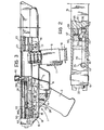
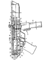
- an automatic fire-arm comprises a frame or support structure, generally indicated 1, comprising a shaped body 2 to which a grip 3 is fixed by means of screws 4.
- the body 2 is shaped substantially in the form of a tray and its wall has a longitudinal slot 5 close to the grip 3, in which a firing lever or trigger 6 is movably mounted.
- the trigger 6 is shown in the position which it adopts when it is released.
- This trigger has a notch 7 in its central portion which, when the trigger is pulled, is engageable with the portion of the bottom wall of the body 2 adjacent the slot 5.
- the wall of the shaped body 2 also has an aperture 8 connected to one end of a tubular element 9 which acts as a guide for a clip or magazine 10 of ammunition.
- This magazine is of the conventional spring type.
- the tubular element 9 is provided with a conventional positioning device, generally indicated 11, for maintaining the magazine 10 in a fixed position relative to the tubular element 9.
- a tubular part 15 is fixed to the shaped body 2 by a pair of pins 16, 17 which extend through the holes of respective lugs 18, 19 fixed to the outer surface of the tubular part 15, and corresponding holes in the side walls of the shaped body 2.
- the tubular part 15 is closed at one end by an end-piece 20.
- Two centering sleeves 21, 22 are fixed in the tubular part 15, which locate respectively the breech and muzzle ends of the barrel 23.
- a chamber 25 Within the tubular part or casing 15, between the end-piece 20 and the breech of the barrel 23, is a chamber 25.
- the rod 26 is indicated a rod which extends longitudinally within the chamber 25.
- the rod 26 has a tang 26a fixed to the end-piece 20, a central portion 26b, and an end portion 26c which faces a barrel 23 and has a reduced diameter so as to define an annular shoulder 27 with the central portion 26b.
- a bolt 28 is movably mounted in the chamber 25.
- the bolt 28 has an internal axial through-hole 29 in which a conventional type of striker mechanism including a thrust member 30 and a firing pin 31, is movably housed.
- the hole 29 In the part facing the barrel 23, the hole 29 has a reduced diameter portion through which the shaft of the firing pin 31 extends against the action of a spring 32.
- the bolt 28 also has an axial hole 35 which opens towards the rod 26.
- the hole 35 is aligned axially with this rod, and has a larger diameter than the central portion 26b of the rod.
- a helical spring 36 is located in the hole 35 of the bolt surrounding the portion 26c of the rod 26. This spring acts at one end against the annular shoulder 27 of the rod 26 and at the other end against the end wall of the hole 35 in the bolt.
- a cocking handle 40 is fixed to the upper part of the bolt 28, and extends through an axial slot 41 in the upper wall of the tubular part 15.
- a hammer block 50 is disposed in the chamber 25 of the tubular part 15.
- the hammer block 50 has a recess 51 in its lower face.
- a sear 52 is rotatably mounted in the recess 51 of the hammer block about a pin 53 which is carried by this block and extends perpendicular to the longitudinal axis of the tubular part 15.
- the hammer block 50 has a hole 55 extending perpendicular to the axis of the pin 53, which is formed in a wall of the recess 51 in a position facing the sear 52.
- this hole 55 are disposed a thrust member 56 and a spring 57 which biasses the thrust member resiliently against the sear 52.
- the end of the sear 52 facing the bolt 28 has a bevel which defines an inclined surface 58.
- the hammer block 50 has an appendage 60 which extends transverse the longitudinal axis of the tubular part 15 and has a guide hole 61 coaxial with the rod 26.
- the diameter of the guide hole 61 is greater than the diameter of the central portion 26b of this rod.
- a helical spring 62 is disposed around the rod 26 and the spring 36, this spring 62 acting at one end against the appendage 60 of the hammer block 50.
- the springs 36, 62 are wound in opposite directions.
- a rocker lever 70 is supported by the shaped body 2 below the tubular part 15 and is pivoted about a pin 71 extending perpendicular to the longitudinal axis of the tubular part 15.
- the ends of the lever 70 have respective projections or teeth 72, 73 which face upwardly and extend through respective apertures 75, 76 in the wall of the tubular element 15 facing the shaped body 2.
- the teeth 72, 73 have rounded profiles.
- the lever 70 is able to adopt a first position, termed the working or retaining position, in which the tooth 72 extends through the aperture 75 of the tubular part 15 and projects into the chamber 25 of this tubular part.
- the lever 70 is also able to adopt a second position, termed the rest position, in which the tooth 73 extends through the aperture 76 in the tubular part 15 and projects into the chamber 25.
- the upper surface of the lever 70 facing the tubular part 15 has a notch 80 in the part between the pin 71 and the tooth 73. This notch has an inclined surface 81 which connects the bottom surface of the notch to the portion of the upper surface of the lever 70 adjacent the tooth 73.
- a pin 82 is fixed to the upper part of the trigger 6 and extends parallel to the pivot pin 71 of the lever 70.
- the pin 82 engages that portion of the upper surface of the lever 70 between the notch 80 and the tooth 73, maintaining the lever in the working position defined above, as shown in Figure 1.
- the sear 52 is thus made to rotate about the pin 53 to allow the further withdrawal of the hammer block 50. During this rotation, the sear 52 compresses the spring 55, through the thrust member 56. As soon as the front end of the sear 52 has passed over the retaining tooth 72, the sear is returned to its initial position by the thrust imparted through the thrust member 56 under the action of the spring 55. In this position, the sear 52 is ready to bear against the rear retaining tooth 72 of the rocker lever 70.
- the bolt 28 When the cocking handle 40 is released, the bolt 28 is returned to its closing position by the extension of the return spring 36. During this return movement the bolt 28 strips a cartridge from the clip or magazine 10 by means of a shaped heel, and thrusts it into the barrel 23 ( Figure 4).
- the hammer block 50 is urged by its return spring 62 and tends to advance, but after moving a very short distance is retained in a withdrawn position by the engagement of the sear 52 with the rear retaining tooth 72 of the rocker lever 70.
- the pressure of the gases produced by the propellant charge acts on the base of the cartridge case, which bears against the front end face of the bolt 28 to achieve temporary contact and cause the withdrawal of the bolt, together with the hammer block 50, towards their respective arming positions.
- the bolt 28 carries the spent cartridge case towards an ejector tooth which is of conventional type (not shown).
- the case knocks against this ejector tooth and is flipped towards an ejector aperture (not shown).
- the bolt 28 clears the aperture 76 through which the tooth 73 of the rocker lever 70 extends, so that the latter again rotates in an anti-clockwise sense due to the action of the inclined plane 58 of the sear 52 of the hammer block on the rear retaining tooth 72.
- the hammer block 50 is released to advance and strike the rear end of the thrust member 30 of the striker mechanism, causing the firing of a subsequent round.
- the automatic fire-arm according to the invention has the advantage of allowing the firing of bursts at a low rate of fire. This results from the delay which is introduced between the moment when the bolt reaches the closing position in each cycle, and the subsequent moment when the hammer block, once released, reaches the striking position.
- a further advantage lies in the noticeable increase in the firing power achieved by the fact that firing occurs with the bolt closed.
Landscapes
- Engineering & Computer Science (AREA)
- General Engineering & Computer Science (AREA)
- Percussive Tools And Related Accessories (AREA)
- Toys (AREA)
- Portable Nailing Machines And Staplers (AREA)
- Aiming, Guidance, Guns With A Light Source, Armor, Camouflage, And Targets (AREA)
- Separation Of Suspended Particles By Flocculating Agents (AREA)
Priority Applications (1)
| Application Number | Priority Date | Filing Date | Title |
|---|---|---|---|
| AT82830096T ATE25427T1 (de) | 1981-05-12 | 1982-04-15 | Automatische feuerwaffe. |
Applications Claiming Priority (2)
| Application Number | Priority Date | Filing Date | Title |
|---|---|---|---|
| IT67641/81A IT1144361B (it) | 1981-05-12 | 1981-05-12 | Arma da fuoco automatica |
| IT6764181 | 1981-05-12 |
Publications (3)
| Publication Number | Publication Date |
|---|---|
| EP0070258A2 true EP0070258A2 (de) | 1983-01-19 |
| EP0070258A3 EP0070258A3 (en) | 1983-04-13 |
| EP0070258B1 EP0070258B1 (de) | 1987-02-04 |
Family
ID=11304135
Family Applications (1)
| Application Number | Title | Priority Date | Filing Date |
|---|---|---|---|
| EP82830096A Expired EP0070258B1 (de) | 1981-05-12 | 1982-04-15 | Automatische Feuerwaffe |
Country Status (23)
| Country | Link |
|---|---|
| US (1) | US4469006A (de) |
| EP (1) | EP0070258B1 (de) |
| JP (1) | JPS5828995A (de) |
| KR (1) | KR860001010B1 (de) |
| AR (1) | AR230760A1 (de) |
| AT (1) | ATE25427T1 (de) |
| AU (1) | AU548296B2 (de) |
| BR (1) | BR8202705A (de) |
| CA (1) | CA1187319A (de) |
| DE (1) | DE3275401D1 (de) |
| DK (1) | DK152626C (de) |
| ES (1) | ES264854Y (de) |
| FI (1) | FI76212C (de) |
| GR (1) | GR75503B (de) |
| IL (1) | IL65586A0 (de) |
| IT (1) | IT1144361B (de) |
| MT (1) | MTP908B (de) |
| NO (1) | NO155745C (de) |
| PH (1) | PH19333A (de) |
| PT (1) | PT74869B (de) |
| TR (1) | TR22234A (de) |
| YU (1) | YU98582A (de) |
| ZA (1) | ZA822833B (de) |
Cited By (1)
| Publication number | Priority date | Publication date | Assignee | Title |
|---|---|---|---|---|
| EP1788476A1 (de) | 2005-11-16 | 2007-05-23 | Brother Kogyo Kabushiki Kaisha | Dokumentsverarbeitungsvorrichtung |
Families Citing this family (17)
| Publication number | Priority date | Publication date | Assignee | Title |
|---|---|---|---|---|
| US4872391A (en) * | 1987-06-02 | 1989-10-10 | Ares, Inc. | Gun for firing telescoped ammunition, plus searing means |
| US5485776A (en) * | 1989-12-16 | 1996-01-23 | Bushman Limited | Mechanism for controlling the firing rate of an automatic weapon |
| US6019024A (en) * | 1998-01-26 | 2000-02-01 | Zdf Import Export, Inc. | Compact operating system for automatic rifles |
| RU2212608C1 (ru) * | 2002-07-15 | 2003-09-20 | Федеральное государственное унитарное предприятие "Центральный научно-исследовательский институт точного машиностроения" | Автоматическое стрелковое оружие |
| RU2231009C1 (ru) * | 2002-10-07 | 2004-06-20 | Низов Николай Константинович | Ударно-спусковой механизм ударникового типа |
| RU2231010C1 (ru) * | 2002-10-07 | 2004-06-20 | Низов Николай Константинович | Спортивно-охотничье оружие |
| RU2235262C1 (ru) * | 2003-03-11 | 2004-08-27 | Открытое акционерное общество "Завод им. В.А. Дегтярёва" | Автоматическое стрелковое оружие |
| US7596900B2 (en) * | 2003-08-04 | 2009-10-06 | Rmdi, L.L.C. | Multi-caliber ambidextrously controllable firearm |
| US7971379B2 (en) | 2004-02-13 | 2011-07-05 | Rmdi, Llc | Firearm |
| US7743543B2 (en) | 2005-10-06 | 2010-06-29 | Theodore Karagias | Trigger mechanism and a firearm containing the same |
| RU2525339C1 (ru) * | 2013-05-07 | 2014-08-10 | Открытое акционерное общество "Концерн "Калашников" | Ударно-спусковой механизм |
| US9377255B2 (en) | 2014-02-03 | 2016-06-28 | Theodore Karagias | Multi-caliber firearms, bolt mechanisms, bolt lugs, and methods of using the same |
| RU2557578C1 (ru) * | 2014-05-07 | 2015-07-27 | Открытое акционерное общество "Центральный научно-исследовательский институт точного машиностроения" | Стрелковое оружие |
| US12215947B2 (en) | 2018-11-30 | 2025-02-04 | Theodore Karagias | Firearm bolt assembly with a pivoting handle |
| US11067347B2 (en) | 2018-11-30 | 2021-07-20 | Theodore Karagias | Firearm bolt assembly with a pivoting handle |
| CZ2020193A3 (cs) * | 2020-04-03 | 2021-05-26 | Česká Zbrojovka A.S. | Sestava kladívka automatiky palné zbraně |
| US12607425B2 (en) * | 2024-06-17 | 2026-04-21 | 3D Defense, Llc | Opposing force recoil reduction in a firearm |
Family Cites Families (8)
| Publication number | Priority date | Publication date | Assignee | Title |
|---|---|---|---|---|
| US1190653A (en) * | 1916-04-12 | 1916-07-11 | Charles F Hughes | Automatic firearm. |
| US1425627A (en) * | 1920-02-24 | 1922-08-15 | Bardelli Arturo | Automatic firearm |
| GB229592A (en) * | 1924-04-14 | 1925-02-26 | Suisse Soc Ind | Improvements in automatic firearms |
| US2224758A (en) * | 1939-03-10 | 1940-12-10 | Savage Arms Corp | Release mechanism for semiautomatic firearms |
| US2357047A (en) * | 1940-07-30 | 1944-08-29 | Savage Arms Corp | Automatic firearm |
| GB604348A (en) * | 1943-01-27 | 1948-07-02 | Eugene Gustavus Reising | Improvements in automatic firearms |
| US2585620A (en) * | 1945-04-14 | 1952-02-12 | Mossberg & Sons O F | Firing mechanism for semi-automatic firearms and safety therefor |
| US3236154A (en) * | 1963-06-28 | 1966-02-22 | Howa Machinery Ltd | Mechanism for reducing the rate of fire in automatic firing arms |
-
1981
- 1981-05-12 IT IT67641/81A patent/IT1144361B/it active
-
1982
- 1982-01-13 US US06/339,224 patent/US4469006A/en not_active Expired - Fee Related
- 1982-04-15 DE DE8282830096T patent/DE3275401D1/de not_active Expired
- 1982-04-15 AT AT82830096T patent/ATE25427T1/de not_active IP Right Cessation
- 1982-04-15 EP EP82830096A patent/EP0070258B1/de not_active Expired
- 1982-04-22 IL IL65586A patent/IL65586A0/xx not_active IP Right Cessation
- 1982-04-26 ZA ZA822833A patent/ZA822833B/xx unknown
- 1982-04-29 ES ES1982264854U patent/ES264854Y/es not_active Expired
- 1982-05-03 MT MT908A patent/MTP908B/xx unknown
- 1982-05-06 TR TR22234A patent/TR22234A/xx unknown
- 1982-05-06 CA CA000402434A patent/CA1187319A/en not_active Expired
- 1982-05-07 GR GR68102A patent/GR75503B/el unknown
- 1982-05-07 JP JP57077394A patent/JPS5828995A/ja active Granted
- 1982-05-07 AU AU83523/82A patent/AU548296B2/en not_active Ceased
- 1982-05-10 YU YU00985/82A patent/YU98582A/xx unknown
- 1982-05-10 FI FI821631A patent/FI76212C/fi not_active IP Right Cessation
- 1982-05-10 PT PT74869A patent/PT74869B/pt unknown
- 1982-05-11 NO NO821554A patent/NO155745C/no unknown
- 1982-05-11 KR KR8202046A patent/KR860001010B1/ko not_active Expired
- 1982-05-11 PH PH27260A patent/PH19333A/en unknown
- 1982-05-11 DK DK210482A patent/DK152626C/da not_active IP Right Cessation
- 1982-05-11 BR BR8202705A patent/BR8202705A/pt not_active IP Right Cessation
- 1982-05-12 AR AR289380A patent/AR230760A1/es active
Cited By (1)
| Publication number | Priority date | Publication date | Assignee | Title |
|---|---|---|---|---|
| EP1788476A1 (de) | 2005-11-16 | 2007-05-23 | Brother Kogyo Kabushiki Kaisha | Dokumentsverarbeitungsvorrichtung |
Also Published As
Similar Documents
| Publication | Publication Date | Title |
|---|---|---|
| EP0070258A2 (de) | Automatische Feuerwaffe | |
| US3306168A (en) | Gas operated semi-automatic pistol | |
| US3857322A (en) | Firearm | |
| US4019423A (en) | Automatic or semi-automatic firearm | |
| US5502914A (en) | Striker cocking and firing mechanism for a handgun | |
| US4580484A (en) | Firearm and firearm conversion unit | |
| US4579037A (en) | Machine pistol with retarded blowback | |
| FI93775C (fi) | Turvavirityksenpoistojärjestelmällä varustettu kivääri | |
| US5160796A (en) | Automatic small arm | |
| US4680884A (en) | Safety firearm mechanism | |
| US4715139A (en) | Closed breech muzzle loader and loading tool | |
| US8176836B2 (en) | Double action short reset trigger system | |
| PT2350550E (pt) | Armas de fogo de recuo retardado com novos mecanismos para o controle do recuo e subida da boca | |
| US4467698A (en) | Angular shape firing pin for use with a collapsible toggle recoil in a hand held weapon | |
| US3090148A (en) | Bolt action firearm with charger | |
| US6016736A (en) | Firearm, particularly a revolver pistol | |
| US4173169A (en) | Semi-automatic firearm | |
| US4448109A (en) | Automatic or semi-automatic firearm | |
| US3029708A (en) | Trigger mechanism for automatic firearms | |
| USH144H (en) | Weapon trigger and sear mechanism | |
| EP1106955A2 (de) | Feuerwaffe mit Inertialschlagbolzen | |
| EP0281793A2 (de) | Munitionszuführvorrichtung für halbautomatische oder mittels Handschieber betätigte Flinten | |
| US5333403A (en) | Muzzle loading rifles | |
| US3183615A (en) | Slide barrel lever action rifle and the like | |
| CA1293632C (en) | Semi-automatic target pistol |
Legal Events
| Date | Code | Title | Description |
|---|---|---|---|
| PUAI | Public reference made under article 153(3) epc to a published international application that has entered the european phase |
Free format text: ORIGINAL CODE: 0009012 |
|
| AK | Designated contracting states |
Designated state(s): AT BE CH DE FR GB LI LU NL SE |
|
| PUAL | Search report despatched |
Free format text: ORIGINAL CODE: 0009013 |
|
| AK | Designated contracting states |
Designated state(s): AT BE CH DE FR GB LI LU NL SE |
|
| 17P | Request for examination filed |
Effective date: 19831004 |
|
| RAP1 | Party data changed (applicant data changed or rights of an application transferred) |
Owner name: SITES - SOCIETA ITALIANA TECNOLOGIE SPECIALI S.P.A |
|
| GRAA | (expected) grant |
Free format text: ORIGINAL CODE: 0009210 |
|
| AK | Designated contracting states |
Kind code of ref document: B1 Designated state(s): AT BE CH DE FR GB LI LU NL SE |
|
| REF | Corresponds to: |
Ref document number: 25427 Country of ref document: AT Date of ref document: 19870215 Kind code of ref document: T |
|
| REF | Corresponds to: |
Ref document number: 3275401 Country of ref document: DE Date of ref document: 19870312 |
|
| ET | Fr: translation filed | ||
| PLBE | No opposition filed within time limit |
Free format text: ORIGINAL CODE: 0009261 |
|
| STAA | Information on the status of an ep patent application or granted ep patent |
Free format text: STATUS: NO OPPOSITION FILED WITHIN TIME LIMIT |
|
| 26N | No opposition filed | ||
| PGFP | Annual fee paid to national office [announced via postgrant information from national office to epo] |
Ref country code: AT Payment date: 19920409 Year of fee payment: 11 |
|
| PGFP | Annual fee paid to national office [announced via postgrant information from national office to epo] |
Ref country code: GB Payment date: 19920410 Year of fee payment: 11 |
|
| PGFP | Annual fee paid to national office [announced via postgrant information from national office to epo] |
Ref country code: DE Payment date: 19920415 Year of fee payment: 11 Ref country code: BE Payment date: 19920415 Year of fee payment: 11 |
|
| PGFP | Annual fee paid to national office [announced via postgrant information from national office to epo] |
Ref country code: CH Payment date: 19920416 Year of fee payment: 11 |
|
| PGFP | Annual fee paid to national office [announced via postgrant information from national office to epo] |
Ref country code: SE Payment date: 19920427 Year of fee payment: 11 |
|
| PGFP | Annual fee paid to national office [announced via postgrant information from national office to epo] |
Ref country code: LU Payment date: 19920429 Year of fee payment: 11 |
|
| PGFP | Annual fee paid to national office [announced via postgrant information from national office to epo] |
Ref country code: NL Payment date: 19920430 Year of fee payment: 11 Ref country code: FR Payment date: 19920430 Year of fee payment: 11 |
|
| EPTA | Lu: last paid annual fee | ||
| PG25 | Lapsed in a contracting state [announced via postgrant information from national office to epo] |
Ref country code: LU Free format text: LAPSE BECAUSE OF NON-PAYMENT OF DUE FEES Effective date: 19930415 Ref country code: GB Effective date: 19930415 Ref country code: AT Effective date: 19930415 |
|
| PG25 | Lapsed in a contracting state [announced via postgrant information from national office to epo] |
Ref country code: SE Effective date: 19930416 |
|
| PG25 | Lapsed in a contracting state [announced via postgrant information from national office to epo] |
Ref country code: LI Effective date: 19930430 Ref country code: CH Effective date: 19930430 Ref country code: BE Effective date: 19930430 |
|
| BERE | Be: lapsed |
Owner name: SITES - SOCIETA ITALIANA TECNOLOGIE SPECIALI S.P. Effective date: 19930430 |
|
| PG25 | Lapsed in a contracting state [announced via postgrant information from national office to epo] |
Ref country code: NL Effective date: 19931101 |
|
| GBPC | Gb: european patent ceased through non-payment of renewal fee |
Effective date: 19930415 |
|
| NLV4 | Nl: lapsed or anulled due to non-payment of the annual fee | ||
| PG25 | Lapsed in a contracting state [announced via postgrant information from national office to epo] |
Ref country code: FR Effective date: 19931229 |
|
| REG | Reference to a national code |
Ref country code: CH Ref legal event code: PL |
|
| PG25 | Lapsed in a contracting state [announced via postgrant information from national office to epo] |
Ref country code: DE Effective date: 19940101 |
|
| REG | Reference to a national code |
Ref country code: FR Ref legal event code: ST |
|
| EUG | Se: european patent has lapsed |
Ref document number: 82830096.2 Effective date: 19931110 |