EP0070696A2 - Connecteur pour jonction de câble et méthode - Google Patents
Connecteur pour jonction de câble et méthode Download PDFInfo
- Publication number
- EP0070696A2 EP0070696A2 EP82303727A EP82303727A EP0070696A2 EP 0070696 A2 EP0070696 A2 EP 0070696A2 EP 82303727 A EP82303727 A EP 82303727A EP 82303727 A EP82303727 A EP 82303727A EP 0070696 A2 EP0070696 A2 EP 0070696A2
- Authority
- EP
- European Patent Office
- Prior art keywords
- connector
- cable
- cables
- connection portions
- insulator
- Prior art date
- Legal status (The legal status is an assumption and is not a legal conclusion. Google has not performed a legal analysis and makes no representation as to the accuracy of the status listed.)
- Granted
Links
- 238000000034 method Methods 0.000 title claims abstract description 14
- 239000012212 insulator Substances 0.000 claims description 24
- 239000011241 protective layer Substances 0.000 claims description 9
- 238000007789 sealing Methods 0.000 claims description 5
- 230000004888 barrier function Effects 0.000 claims description 3
- 239000000615 nonconductor Substances 0.000 claims 5
- 238000009826 distribution Methods 0.000 abstract description 6
- 239000000463 material Substances 0.000 abstract description 6
- 238000004519 manufacturing process Methods 0.000 abstract description 3
- 239000000853 adhesive Substances 0.000 description 12
- 230000001070 adhesive effect Effects 0.000 description 12
- 239000010410 layer Substances 0.000 description 9
- 239000002184 metal Substances 0.000 description 8
- 229910052751 metal Inorganic materials 0.000 description 8
- 229920000642 polymer Polymers 0.000 description 8
- 238000009413 insulation Methods 0.000 description 6
- 230000007935 neutral effect Effects 0.000 description 6
- 238000005304 joining Methods 0.000 description 5
- 238000009434 installation Methods 0.000 description 4
- 238000002955 isolation Methods 0.000 description 4
- XLYOFNOQVPJJNP-UHFFFAOYSA-N water Substances O XLYOFNOQVPJJNP-UHFFFAOYSA-N 0.000 description 4
- 239000004831 Hot glue Substances 0.000 description 3
- 239000004020 conductor Substances 0.000 description 3
- 238000010292 electrical insulation Methods 0.000 description 3
- 238000013459 approach Methods 0.000 description 2
- 239000010426 asphalt Substances 0.000 description 2
- 230000007613 environmental effect Effects 0.000 description 2
- 238000010438 heat treatment Methods 0.000 description 2
- NJPPVKZQTLUDBO-UHFFFAOYSA-N novaluron Chemical compound C1=C(Cl)C(OC(F)(F)C(OC(F)(F)F)F)=CC=C1NC(=O)NC(=O)C1=C(F)C=CC=C1F NJPPVKZQTLUDBO-UHFFFAOYSA-N 0.000 description 2
- 239000000126 substance Substances 0.000 description 2
- RYGMFSIKBFXOCR-UHFFFAOYSA-N Copper Chemical compound [Cu] RYGMFSIKBFXOCR-UHFFFAOYSA-N 0.000 description 1
- 241000238413 Octopus Species 0.000 description 1
- 229910000831 Steel Inorganic materials 0.000 description 1
- 230000001154 acute effect Effects 0.000 description 1
- 238000009933 burial Methods 0.000 description 1
- 238000005266 casting Methods 0.000 description 1
- 238000009833 condensation Methods 0.000 description 1
- 230000005494 condensation Effects 0.000 description 1
- 238000010276 construction Methods 0.000 description 1
- 229910052802 copper Inorganic materials 0.000 description 1
- 239000010949 copper Substances 0.000 description 1
- 229920003020 cross-linked polyethylene Polymers 0.000 description 1
- 239000004703 cross-linked polyethylene Substances 0.000 description 1
- 230000006866 deterioration Effects 0.000 description 1
- 239000003989 dielectric material Substances 0.000 description 1
- 238000003618 dip coating Methods 0.000 description 1
- 238000005516 engineering process Methods 0.000 description 1
- 239000003822 epoxy resin Substances 0.000 description 1
- 238000012986 modification Methods 0.000 description 1
- 230000004048 modification Effects 0.000 description 1
- 239000004033 plastic Substances 0.000 description 1
- 229920003023 plastic Polymers 0.000 description 1
- 229920000647 polyepoxide Polymers 0.000 description 1
- 239000004800 polyvinyl chloride Substances 0.000 description 1
- 229920000915 polyvinyl chloride Polymers 0.000 description 1
- 238000011084 recovery Methods 0.000 description 1
- 238000009877 rendering Methods 0.000 description 1
- 229920005989 resin Polymers 0.000 description 1
- 239000011347 resin Substances 0.000 description 1
- 239000007787 solid Substances 0.000 description 1
- 239000010959 steel Substances 0.000 description 1
Images
Classifications
-
- H—ELECTRICITY
- H01—ELECTRIC ELEMENTS
- H01R—ELECTRICALLY-CONDUCTIVE CONNECTIONS; STRUCTURAL ASSOCIATIONS OF A PLURALITY OF MUTUALLY-INSULATED ELECTRICAL CONNECTING ELEMENTS; COUPLING DEVICES; CURRENT COLLECTORS
- H01R31/00—Coupling parts supported only by co-operation with counterpart
- H01R31/02—Intermediate parts for distributing energy to two or more circuits in parallel, e.g. splitter
-
- H—ELECTRICITY
- H01—ELECTRIC ELEMENTS
- H01R—ELECTRICALLY-CONDUCTIVE CONNECTIONS; STRUCTURAL ASSOCIATIONS OF A PLURALITY OF MUTUALLY-INSULATED ELECTRICAL CONNECTING ELEMENTS; COUPLING DEVICES; CURRENT COLLECTORS
- H01R4/00—Electrically-conductive connections between two or more conductive members in direct contact, i.e. touching one another; Means for effecting or maintaining such contact; Electrically-conductive connections having two or more spaced connecting locations for conductors and using contact members penetrating insulation
- H01R4/28—Clamped connections, spring connections
- H01R4/30—Clamped connections, spring connections utilising a screw or nut clamping member
-
- H—ELECTRICITY
- H01—ELECTRIC ELEMENTS
- H01R—ELECTRICALLY-CONDUCTIVE CONNECTIONS; STRUCTURAL ASSOCIATIONS OF A PLURALITY OF MUTUALLY-INSULATED ELECTRICAL CONNECTING ELEMENTS; COUPLING DEVICES; CURRENT COLLECTORS
- H01R4/00—Electrically-conductive connections between two or more conductive members in direct contact, i.e. touching one another; Means for effecting or maintaining such contact; Electrically-conductive connections having two or more spaced connecting locations for conductors and using contact members penetrating insulation
- H01R4/70—Insulation of connections
-
- Y—GENERAL TAGGING OF NEW TECHNOLOGICAL DEVELOPMENTS; GENERAL TAGGING OF CROSS-SECTIONAL TECHNOLOGIES SPANNING OVER SEVERAL SECTIONS OF THE IPC; TECHNICAL SUBJECTS COVERED BY FORMER USPC CROSS-REFERENCE ART COLLECTIONS [XRACs] AND DIGESTS
- Y10—TECHNICAL SUBJECTS COVERED BY FORMER USPC
- Y10S—TECHNICAL SUBJECTS COVERED BY FORMER USPC CROSS-REFERENCE ART COLLECTIONS [XRACs] AND DIGESTS
- Y10S439/00—Electrical connectors
- Y10S439/932—Heat shrink material
Definitions
- This invention relates to power cable jointing.
- Single core cables are now all polymer insulated, using materials such as polyvinylchloride or cross-linked polyethylene.
- Multicore cables are either polymer or paper insulated and are, in the majority of cases, either four-core or three-core with surrounding neutral/ground wires.
- Paper insulated multicore cables are all metal sheathed and oil-filled, some draining, some non-draining.
- Polymer insulated multicore cables may be armoured with steel wires or tapes.
- Most low voltage installations today are three phase plus neutral and/or ground. In the majority of cases, neutral and ground are now combined.
- reference to a single core cable is often synonymous with single phase.
- in-line joints are made when two cables are connected together end-to-end or when a cable is repaired after failure.
- a branch joint (T-joint) is made when a second main cable is jointed into the first main cable.
- the third type of joint, service connections are taps into the distribution network for small consumers, such as homes, small factories or street lighting.
- the number of service cables which can be connected to the main cable via a service joint can presently be as high as six, but four is more typical. It is desirable for service connections to be re-enterable to provide for additional services or to break and remake existing connections.
- cables were initially paper insulated and easily damaged by moisture ingress. Joints for such cables consisted of metal half- shells filled with an insulation medium such as oil or bitumen.
- an insulation medium such as oil or bitumen.
- One such modification is the use of casting resin to replace bitumen and a simple vacuum-formed housing to replace the metal shell.
- various compatibility problems arose.
- One of the more widely used solutions to multicore cable jointing compatibility problems was the low voltage distribution pillar-pedestal, into which the cables were brought and interconnections made using a series of small bus bars, thus providing a miniature version of an indoor distribution board.
- Such a pedestal is typically ground mounted, about 75 cms (30 inches) high and 37 cms (15 inches) square and is often regarded by engineers as a poor alternative to underground jointing.
- the pedestal is not compact in size and is subject to problems such as condensation, flooding and vehicular damage.
- a recent invention in this area is a low voltage single phase multiple connector (“the octopus”), which is a small, insulated bus bar-type device which allows individual connection points to be accessed, and a butt connection to be made and subsequently sealed without effecting other connections.
- the octopus is a small, insulated bus bar-type device which allows individual connection points to be accessed, and a butt connection to be made and subsequently sealed without effecting other connections.
- Multicore cables are very rigid and their cores not easily bent. If three phase devices of this design were to be produced, they would not be compact and would require four or five separate bus bars, depending on whether neutral and ground were combined.
- the butt-style of connection would result in unacceptably long lengths of bare cores, which would pose an especial hazard if connections were made under tension.
- a connector for jointing electrical power cables comprising: at least two current carrying elements, each having at least three connection portions to which individual cable cores may be attached, the connection portions of one current carrying element being positioned adjacent to corresponding connections portions of other current carrying elements to define respective connector outlets, one outlet for each cable to be connected; and an electrically insulating body substantially surrounding the current carrying elements and extending at least up to the connection portions, the insulating body electrically insulating the current carrying elements from one another and being arranged to isolate the cables, which, in use, are attached to the connector, from one another.
- the isolation of the cables that is provided by the insulating body of the connection is such as to allow for electrical interconnection of cables that would otherwise not be compatible physically and/or chemically, for example by being of different size, configuration or material.
- One advantage of the connector is that it provides chemical isolation of the cables, this being especially important, for example, where one only of the cables is oil-filled and the other may be damaged by contact with the oil. Such isolation may be achieved whilst allowing for in-line, branch or service joints to be made and also whilst providing for environmental sealing adequate for underground burial of the jointed cables.
- tandem connector comprising two or more connectors according to said one aspect of the present invention, said connectors being joined together at the connection portions of at least one connector outlet of each connector, to provide additional outlets to which cables may be connected.
- a method of jointing electrical power cables comprising the steps of: removing a portion of the outer protective layer of each cable to be jointed to expose the cable cores; positioning between the cables a cable jointing connector according to said one or said further aspect of the present invention, said cable jointing connector acting as a barrier thereby to isolate the cables from each other; and electrically connecting the exposed cores of the cables to respective connection portions of the connector.
- connection portions are provided, as a discrete, or alternatively integral, extension of the insulating body, for at least one, and advantageously each, of the connection portions so as to surround at least a part of the connection portions.
- This insulation may be phase colour-coded.
- insulation is preferably provided over the interconnected connection portions and cable cores.
- Electrical insulation may also be provided to protect the overall connection between the cables and the connector.
- the electrical interconnection of a tandem connector is also preferably insulated.
- Electrical insulation and environmental sealing may be provided by polymeric components, which are preferably heat-shrinkable, and which may be adhesive-coated.
- the connector may be very compact, and is preferably compatible with round cables so as to match the configuration of the cables thereby enabling efficient utilisation of space.
- branch or service connections may be provided by assembling cable jointing connectors in combination or by fabricating a connector with current carrying elements having many connection portions.
- the invention can thus provide a compact connector which allows single phase and multi-phase cables to be jointed.
- the jointed connections may be re-entered without difficulty, thereby rendering the system less expensive and relatively craft- insensitive.
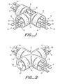
- Figure 1 illustrates a re-enterable cable jointing connector 2 having two male main outlets 4 and one male branch outlet 6.
- the connector 2 has four T-shaped current carrying elements 8 each having three connection portions 10, which project from respective ones of the branch outlets. Only one of the elements 8 is shown (partially) within the body of the connector 2.
- connection portions 10 together comprise a "connector outlet", shown generally at 12.
- Each outlet 12 provides electrical connection capability for one cable. If a main cable is to be connected, the connector outlet is called a “main outlet”, and may be further characterised as “male”, if it protrudes, or as “female” if it surrounds.
- Figure 1 illustrates two male main outlets 4.
- Figure I further illustrates a male branch outlet 6.
- a "branch outlet” is an outlet to which a branch cable is to be connected.
- Single core cables may be connected to multi- core cables, as well as single core to single core and multi-core to multi-core.
- a “tandem outlet” is an outlet to which another outlet may be joined in tandem.
- Figure 2 shows a female tandem outlet 38. Tandem joining may be directly accomplished male to male or male to female.
- Female to female tandem joining is possible but would require a male-male interconnection assembly (not shown).
- female to female or male to female joining would require a joining harness (not shown), such as a strap, especially at high amperage levels.
- Any number of branch or service connections may be provided by assembling cable jointing connectors in combination by interconnecting tandem outlets, two or more of which are joined together at the connection portions of at least one connector outlet of each connector.
- a branch or service outlet may be used as a tandem outlet when joined as stated above.
- The, current carrying elements 8 are shown in a cut-away as having a planar T-shaped configuration. They may also have a Y-shaped configuration, and in any event, need not lie in one plane.
- the current carrying elements 8 are shown as bus bars which have been stamped-out of suitable sheet metal, such as copper, for ease of fabrication, although other methods of fabrication may be employed.
- An electrically insulating body 14 is shown substantially surrounding the current carrying elements 8 and extending up to the connection portions 10.
- the insulating body 14 electrically insulates the current carrying elements from one another and isolates the cables to be jointed from one another.
- the body 14 may be formed from any dielectric material, such as, for example, a cast or moulded epoxy resin. The simplicity of the design and construction of the connector 2 will be appreciated from Figure 1.
- Electrically insulating extension layers 16 are also shown in Figure 1. These extend from the insulating body 14 and surround at least part of each connection portion 10.
- the extension layers 16 may be formed (i) by dip-coating the current carrying elements 8 in part or in their entirety, after they have been formed, (ii) by utilising polymeric sleeves (as shown in Figure 1) positioned over and around the current carrying elements 8 so that they extend from the insulating body 14, (iii) by being formed integrally with the insulating body It itself, or (iv) by wrapping insulating tape around the elements 8.
- extension layers 16 are polymeric sleeves, they are preferably heat-shrinkable, and advantageously are adhesive-coated.
- Figure 1 shows extension layers 16 in the form of heat-shrunk sleeves in place, having been shrunk into circumferential contact with respective elements 8.
- the extension layers 16 may be phase colour-coded according to the international colour-coding convention, to identify, and thus to facilitate connection of, corresponding connection portions of respective connector outlets.
- Dip-coated connection portions 10 may be ring cut in the field to expose at least a small electrically conductive portion of the current carrying elements 8, such as at least the holes 18 in the connection portions 10.
- Cables may comprise several protective layers, such as an outer polymeric sheath, an armoured sheath and an insulating layer or layers, herein referred to collectively as "an outer protective layer".
- Current is carried by conductive cores contained within the outer protective layer. These conductive cores may be independently insulated.
- core refers to any element within the cable which is able to carry electric current and hence encompasses solid metal conductors, a bundle of metal wires forming a conductor, or metallic wires, braided sleeves or meshes, which serve as neutral or ground leads, carrying power back to the generator or to ground respectively.
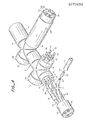
- Cables which are to be jointed are prepared by first removing a portion of the outer protective layer to expose the cable ceres. If the cable cores are independently insulated, a portion of this insulation is removed also. This is illustrated in Figure 4, where a main cable 20 has had its outer protective layer 22 removed to expose the individually insulated cores 24 within.
- a stripped core 26 is shown in Figure 4 as being fitted with a crimp lug 28, which has a hole 30 which may be matched to the hole 18 formed in connection portions 10 for securement thereto.
- a bolt 32 or the like is inserted through the overlappingly matched holes 30 and 18 to secure the connection, although other methods of securing the connection may be employed.
- FIG. 4 also shows individual connection insulators 34 which are depicted as preferred heat-shrinkable sleeves, although they could comprise sleeves of another type, or tape.
- Each individual connection insulator 34 is slid over a stripped core 26 and on to an insulated core 24 before a crimp lug 28 are joined. The insulator 34 may then be repositioned after connection of the crimp lug 28 to the connection portion 10 thereby enclosing the connection portion 10, overlapping the individual insulated cable core 24 at one extremity and extending substantially up'to the insulating body 14 at the other extremity.
- the individual connection insulators 34 are repositioned around the connection portions 10 to enclose the connection portion 10 and to overlap the individual insulated cable cores 24 at one extremity and to overlap the extension layers 16 at the other extremity.
- the individual connection insulators 34 are polymeric sleeves, they may be heat-shrinkable polymeric sleeves, in which case, heat is applied to shrink the sleeve into circumferential contact once it has been repositior as indicated.
- the sleeve may be adhesive-coated and the adhesive is a hot-melt adhesive, the application of heat serves also to cause the adhesive to flow and to form an integral seal as it cools.
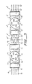
- Figure 2 illustrates a re-enterable cable jointing connector 2 having two male main outlets 4, one male service outlet 36 and one female tandem outlet 38.
- the female tandem outlet 38 is for the purpose of interconnecting two or more re-enterable cable jointing connectors 2 to form connectors having many service outlets, such as by joining a male tandem outlet 40 (shown in Figure 3) to a female outlet of another connector.
- a female tandem outlet 38 is formed by extending the insulating body 14 over the connection portions 10 on one side of the insulating body 14 so as to substantially surround the connection portions 10 on that side.
- the structure of the connection portions 10 are in this instance of a type which surrounds, for example, the cable core to be connected, as opposed to being of the type which protrudes.
- the current carrying elements 8 in Figure 2 have a crossed-configuration in one plane, but they may also have an X- or an H-shaped configuration and in any event, need not lie in one plane.
- Figure 3 illustrates two re-enterable cable jointing connectors 2 and 2', each having four male outlets: two main outlets 4, 4 and 4', 4', one main outlet of each serving simultaneously as a male tandem outlet 40 and 40', and two service outlets 36, 36 and 36', 36'.
- the male tandem outlets 40 and 40' are joined by overlapping the holes 18 and 18' of their respective connection portions 10 and 10' and inserting a bolt 32 through them to secure the connection.
- Any number of re-enterable cable jointing connectors 2 may be connected in tandem in this manner, and bolting is given as one example only among several possible methods of securing the interconnections.
- tandem connections, male to female, and tandem connections, male to male (shown in Figure 3) are possible.
- connection portions 10 and 10' which are shown as rectangular bus bars, but which could be circular, or of other cross-section, is described in U.K.Patent Specification No.1,571,380, herein incorporated by reference.
- a heat-recoverable metal member is positioned about a socket member, which socket member may be attached to a conductor such as the connection portions 10 of the current carrying elements 8. The recovery of the metal member deforms a deformable portion of the socket to ensure the connection.
- connection portions 10 and 10' of Figure 3 may be electrically insulated by providing a plurality of interconnection insulators, arranged to overlap respective pairs of interconnected connection portions.
- These insulators may be heat-shrinkable polymeric sleeves, in which case installation includes the step of heating to cause shrinking into circumferential contact.
- the sleeves may be adhesive-coated and when the adhesive is a hot-melt adhesive, the application of heat serves also to cause the adhesive to flow and to form an integral seal as it cools.
- the joined connection portions of Figure 3 may be environmentally sealed (not shown) by providing an overall interconnection insulator, which is electrically insulating and which is positioned over and around the pair of interconnected connectors to enclose the interconnection, overlapping each insulating body of said pair of interconnected connectors. If several connectors are joined in combination, one overall insulator is provided for each pair joined.
- These insulators preferably are heat-shrinkable polymeric sleeves, in which case installation includes the step of heating to cause shrinking into circumferential contact.
- the sleeves are adhesive-coated.
- the adhesive is a hot-melt adhesive, the application of heat to cause shrinking of the sleeve, serves also to cause the adhesive to flow and to form an integral seal as it cools.
- Figure 4 illustrates a re-enterable cable jointing connector 2 which is fabricated to have six male outlets: two main outlets 4 and four service outlets 36.
- the cable cores of the cable 20 are shown in partial expanded view as being connected to connection portions 10 of a male main outlet 4, each cable core being connected to a respective connection portion 10.
- Two of the male service outlets 36 are shown terminated by caps 42 which are preferably fabricated of heat-shrinkable polymeric materials and which are preferably lined with an adhesive. After positioning each cap so as to enclose a connector outlet, thereby insulating and sealing the connector outlet, where the cap is heat-shrinkable, heat is applied to cause it to shrink into circumferential contact.
- Service outlet 36 and main outlet 4 are both shown with cables already connected and respective overall insulators 44 in place.
- the overall insulators 44 are shown in Figure 4 as heat-shrinkable polymeric sleeves which have been circumferentially positioned and shrunk by the application of heat into circumferential contact.
- Each overall insulator 44 is electrically insulating and is positioned over and around a connected cable 46 to enclose the connected cable cores 48 and to extend transversely on either side thereof, over-lapping the insulated cable at one extremity and overlapping the insulating body at the connector outlets at the other extremity.
- a cable may be isolated physically and chemically by attaching the cores of said cable to connection portions 10 on one side of the moulded body 14 so that said moulded body 14 acts as a barrier.
- Additional physical and chemical isolation may advantageously be provided by pre-treating and pre-sealing the cables, especially multi-core cables by means of, for example, cable break-out sleeves (not shown). These seal the truncated cables and especially the crotch areas between individual cable cores, while allowing cable cores to be broken-out individually from the cable for connection purposes.
- Cable break-out sleeves are preferably of heat-shrinkable polymeric materials. They serve to retain oil within paper insulated cables and to prevent water, which may inadvertently enter and channel down the interstices of polymer insulated cables, from entering the connection outlet areas of the cable jointing connectors.
- Figure 4 shows the connector as having six outlets formed by stacking and staggering the four current carrying elements which are bus bars.
- the bus bars at one outlet 36 have been numbered 50, 52, 54 and 56.
- Bus bars 50 and ' 56 are identical stampings which are symmetrical about a long portion having a long axis, i.e. having six legs of equal length.
- Bus bars 52 and 54 are identical stampings which are asymmetrical about a long portion having a long axis, i.e. having two legs on one side and one leg on one end of the long portion which are shorter than the other three legs. This allows for a very compact stacking and staggering arrangement which provides that the outlet be compatible with round cables and the space be used efficiently.
- Bus bars 50 and 56 are spacially stacked one above the other.
- Bus bars 52 and 54 are first stacked in alignment with one another and then one is rotated 180° with respect to the other in the same plane in which they lie.
- bus bar 52 is interposed above bus bar 50 such that its long portion lies parallel to the long portion of bus bar 50, but its short-legged side is staggered to the left of bus bar 50.
- bus bar 54 is interposed above bus bar 52 such that its long portion lies parallel to the long portion of bus bar 50, but its short-legged side is staggered to the right of bus bar 50.
- An alternative method of stacking and staggering four current carrying elements in order to result in a spacially-efficient, configuration compatible with round cables consists of stamping four identical bus bars (not shown) all of which are asymmetrical about a long portion having a long axis, i.e. having 2 legs on one side and one leg on one end of the long portion which are shorter than the others, such as bus bars 52 and 54 in the previous example. These may then be alternately stacked and rotated and may be called 52, 54 and 52', 54' (not shown).
- the stacking arrangement is that initially all four bus bars are stacked and aligned together. Then, 52 and 52' are pulled out and stacked one with respect to the other, 52' being stacked above 52. Next, 54 and 54' are rotated 180 * in the plane in which they lie. They are then interposed between 52 and 52' as follows: 54' is staggered to the left of 52 and interposed spacially above 52, while 54 is staggered to the right of 52 and inserted spacially above 54 but below 52', in every case, aligning in parallel the long portions of each.
Landscapes
- Cable Accessories (AREA)
- Coupling Device And Connection With Printed Circuit (AREA)
- Multi-Conductor Connections (AREA)
Priority Applications (1)
| Application Number | Priority Date | Filing Date | Title |
|---|---|---|---|
| AT82303727T ATE22759T1 (de) | 1981-07-16 | 1982-07-15 | Verbinder fuer kabelverbindung und verfahren. |
Applications Claiming Priority (2)
| Application Number | Priority Date | Filing Date | Title |
|---|---|---|---|
| US283843 | 1981-07-16 | ||
| US06/283,843 US4415217A (en) | 1981-07-16 | 1981-07-16 | Cable joining connector and method |
Publications (3)
| Publication Number | Publication Date |
|---|---|
| EP0070696A2 true EP0070696A2 (fr) | 1983-01-26 |
| EP0070696A3 EP0070696A3 (en) | 1984-02-29 |
| EP0070696B1 EP0070696B1 (fr) | 1986-10-08 |
Family
ID=23087798
Family Applications (1)
| Application Number | Title | Priority Date | Filing Date |
|---|---|---|---|
| EP82303727A Expired EP0070696B1 (fr) | 1981-07-16 | 1982-07-15 | Connecteur pour jonction de câble et méthode |
Country Status (7)
| Country | Link |
|---|---|
| US (1) | US4415217A (fr) |
| EP (1) | EP0070696B1 (fr) |
| AT (1) | ATE22759T1 (fr) |
| BR (1) | BR8204137A (fr) |
| CA (1) | CA1182879A (fr) |
| DE (1) | DE3273698D1 (fr) |
| GB (1) | GB2109172B (fr) |
Cited By (2)
| Publication number | Priority date | Publication date | Assignee | Title |
|---|---|---|---|---|
| EP0195133A3 (fr) * | 1985-03-18 | 1988-07-06 | Josef Schlemmer GmbH | Dispositif de couplage et de distribution électrique |
| WO1998011635A1 (fr) * | 1996-09-13 | 1998-03-19 | Derek Linaker | Ensemble de connexion electrique |
Families Citing this family (33)
| Publication number | Priority date | Publication date | Assignee | Title |
|---|---|---|---|---|
| US4552430A (en) * | 1982-09-30 | 1985-11-12 | Myers Electric Products, Inc. | Connector head for electric terminal box |
| GB8325402D0 (en) * | 1983-09-22 | 1983-10-26 | Raychem Gmbh | Electrical apparatus |
| GB8426748D0 (en) * | 1984-10-23 | 1984-11-28 | Ranton & Co Ltd | Electrical accessory connections |
| US4898547A (en) * | 1985-07-30 | 1990-02-06 | Paradyne Corp. | Hybrid interface adapter |
| DE3644609A1 (de) * | 1986-12-29 | 1988-07-07 | Guenter Kreitz | Verbindungsstueck fuer heizbaender von elektrischen begleitheizungen |
| US4911652A (en) * | 1988-06-22 | 1990-03-27 | J.B. Nottingham & Co. | Emergency power distribution system |
| USD341817S (en) | 1990-08-16 | 1993-11-30 | Turn-Luckily International Inc. | Electrical connector |
| US5203712A (en) * | 1992-01-17 | 1993-04-20 | Amp Incorporated | Circuit wiring device |
| DE9207882U1 (de) * | 1992-06-11 | 1992-08-13 | Siemens Ag, 8000 Muenchen | Steckverbindersystem |
| US5626479A (en) * | 1993-07-16 | 1997-05-06 | Hughes; Michael T. | Unified connector interface adapter |
| US5747742A (en) * | 1995-10-16 | 1998-05-05 | Lucent Technologies, Inc. | Protective wrapping for spliced cable connectors |
| US5971799A (en) * | 1997-04-26 | 1999-10-26 | Swade; George | Y-shaped harness for the interconnection between a vehicle radio, a vehicle harness and add-on electronic device |
| US5911600A (en) * | 1997-07-25 | 1999-06-15 | Itt Manufacturing Enterprises, Inc. | Three port connector |
| USD418816S (en) * | 1998-09-28 | 2000-01-11 | Commercial & Industrial Design Co., Inc. | Modular power connector |
| US6241369B1 (en) * | 1998-11-20 | 2001-06-05 | Cooper Technologies Company | Quick mount fixture |
| TW498959U (en) * | 2000-01-27 | 2002-08-11 | Shining Blick Enterprises Co | Quick connecting structure of neon light |
| US7179130B2 (en) * | 2002-07-01 | 2007-02-20 | Judge Kerry J | Solenoid connector |
| FR2850485B1 (fr) * | 2003-01-29 | 2005-04-15 | Labinal | Systeme de modification de la structure d'un harnais electrique |
| AT414062B (de) * | 2004-05-17 | 2006-08-15 | Swarovski & Co | Elektrischer verteiler |
| US7401946B2 (en) * | 2004-07-07 | 2008-07-22 | Pent Technologies, Inc. | Modular wiring for linear lighting |
| WO2007043896A1 (fr) * | 2005-10-07 | 2007-04-19 | Phillip Smith | Ensemble modulaire |
| USD571293S1 (en) * | 2005-12-14 | 2008-06-17 | Tii Network Technologies, Inc. | Power protection module |
| MX2007002691A (es) * | 2007-03-06 | 2008-09-05 | Jose Marco Salinas Garcia | Segunda generacion aislador pared gruesa galvanizada (et-2g-apgg). |
| US8347533B2 (en) * | 2007-10-11 | 2013-01-08 | Southwire Company | Machine applied labels to armored cable |
| US20100271804A1 (en) * | 2009-04-22 | 2010-10-28 | Levine Jonathan E | Modular lighting device kit |
| US8951067B2 (en) * | 2012-10-01 | 2015-02-10 | Henge Docks Llc | Docking station for an electronic device having improved connector interface |
| US9331459B2 (en) * | 2012-11-13 | 2016-05-03 | Michael Clark | Generator coupling kit and methods thereof |
| US11031157B1 (en) | 2013-08-23 | 2021-06-08 | Southwire Company, Llc | System and method of printing indicia onto armored cable |
| AU2015408326B2 (en) * | 2015-09-10 | 2020-07-16 | Connec Limited | An electrical connection system for use in high power applications |
| WO2017184838A1 (fr) * | 2016-04-20 | 2017-10-26 | Hubbell Incorporated | Boîtier de socle pour composants utilitaires |
| US10869401B1 (en) * | 2017-06-15 | 2020-12-15 | Oberon, Inc | Wireless bollard |
| DE102024105293A1 (de) * | 2024-02-26 | 2025-08-28 | Harting Electric Stiftung & Co. Kg | Elektrischer Verteiler |
| US12545196B2 (en) * | 2024-03-06 | 2026-02-10 | Geotab Inc. | Splitter harness for vehicles with a proprietary interface port connector |
Family Cites Families (9)
| Publication number | Priority date | Publication date | Assignee | Title |
|---|---|---|---|---|
| US540540A (en) * | 1895-06-04 | Underground electrical conductor and method of manufacturing same | ||
| DE859775C (de) * | 1950-09-27 | 1952-12-15 | Siemens Ag | Abzweigstueck fuer Installationsanlagen |
| GB1303654A (fr) * | 1969-03-13 | 1973-01-17 | ||
| FR2054879A5 (fr) * | 1969-07-30 | 1971-05-07 | Sumitomo Electric Industries | |
| DE2041132A1 (de) * | 1970-08-19 | 1972-02-24 | Erich Pechstein | Schutzkontaktsteckerkupplung |
| ZA722148B (en) * | 1971-03-31 | 1972-12-27 | Raychem Corp | Cable splice |
| US3851296A (en) * | 1972-09-01 | 1974-11-26 | Raychem Corp | Cable coupling |
| JPS52121790A (en) | 1976-10-28 | 1977-10-13 | Raychem Ltd | Connector and method of manufacturing thereof |
| DE2837396A1 (de) * | 1978-08-26 | 1980-03-06 | Kabel Metallwerke Ghh | Muffe fuer abzweig- und verbindungsstellen von elektrischen kabeln oder rohrbuendelkabel |
-
1981
- 1981-07-16 US US06/283,843 patent/US4415217A/en not_active Expired - Lifetime
-
1982
- 1982-07-15 BR BR8204137A patent/BR8204137A/pt unknown
- 1982-07-15 CA CA000407385A patent/CA1182879A/fr not_active Expired
- 1982-07-15 AT AT82303727T patent/ATE22759T1/de not_active IP Right Cessation
- 1982-07-15 GB GB08220536A patent/GB2109172B/en not_active Expired
- 1982-07-15 EP EP82303727A patent/EP0070696B1/fr not_active Expired
- 1982-07-15 DE DE8282303727T patent/DE3273698D1/de not_active Expired
Cited By (2)
| Publication number | Priority date | Publication date | Assignee | Title |
|---|---|---|---|---|
| EP0195133A3 (fr) * | 1985-03-18 | 1988-07-06 | Josef Schlemmer GmbH | Dispositif de couplage et de distribution électrique |
| WO1998011635A1 (fr) * | 1996-09-13 | 1998-03-19 | Derek Linaker | Ensemble de connexion electrique |
Also Published As
| Publication number | Publication date |
|---|---|
| EP0070696B1 (fr) | 1986-10-08 |
| GB2109172A (en) | 1983-05-25 |
| GB2109172B (en) | 1985-08-07 |
| CA1182879A (fr) | 1985-02-19 |
| DE3273698D1 (en) | 1986-11-13 |
| US4415217A (en) | 1983-11-15 |
| ATE22759T1 (de) | 1986-10-15 |
| EP0070696A3 (en) | 1984-02-29 |
| BR8204137A (pt) | 1983-07-12 |
Similar Documents
| Publication | Publication Date | Title |
|---|---|---|
| EP0070696B1 (fr) | Connecteur pour jonction de câble et méthode | |
| CA1062784A (fr) | Connecteur de jonction de cables d'alimentation amovible avec possibilite de fixation aux elements du systeme | |
| US6227908B1 (en) | Electric connection | |
| US6658735B2 (en) | Crimping terminal for connection between electric cables | |
| CA2794733C (fr) | Procedes et systemes pour former un ensemble jonction protege pouvant etre deconnecte | |
| JPH0364873A (ja) | 圧接ターミナル | |
| IE832036L (en) | Optic fibre connection system | |
| JPS5939970B2 (ja) | 内部伝熱ジヤケツトを持つたスプライス・コネクタ | |
| EP0087267B1 (fr) | Connecteur électrique pour haute-tension et assemblage de connecteur | |
| EP0136154A2 (fr) | Jonctions et terminaisons de câbles | |
| EP3857063B1 (fr) | Système de connexion de descente de paratonnerre, système de protection contre la foudre d'une éolienne, et procédé d'agencement d'un système de connexion de descente de paratonnerre | |
| EP0659300A1 (fr) | Conduite rigide munie de bus | |
| US20180131171A1 (en) | Sleeve for Shielding Electrical Joint | |
| US5484300A (en) | Pre-bussed rigid conduit | |
| EP0253670A2 (fr) | Connecteur de câble | |
| CA1261419A (fr) | Connecteur en ligne | |
| US6062917A (en) | Versatile cable connector system for medium voltage underground electrical transmission distribution and the like | |
| RU235284U1 (ru) | Гибридная кабельная муфта для кабелей среднего напряжения | |
| GB2293497A (en) | Repairing cable installations | |
| US5648640A (en) | Re-insulation of conductor junctions of primary conductors | |
| JP2023111882A (ja) | Hvdc電力ケーブル多分岐接合アセンブリ | |
| EP0071482A1 (fr) | Ensemble de connexion et méthode pour câbles de puissance | |
| EP0624920B1 (fr) | Connexion électrique | |
| KR101093284B1 (ko) | 초고압 케이블 접속함의 클램프형 접지단자 | |
| WO2024134513A1 (fr) | Système de reduction de tension de connecteur de câble |
Legal Events
| Date | Code | Title | Description |
|---|---|---|---|
| PUAI | Public reference made under article 153(3) epc to a published international application that has entered the european phase |
Free format text: ORIGINAL CODE: 0009012 |
|
| 17P | Request for examination filed |
Effective date: 19820809 |
|
| AK | Designated contracting states |
Designated state(s): AT BE CH DE FR IT LI NL SE |
|
| PUAL | Search report despatched |
Free format text: ORIGINAL CODE: 0009013 |
|
| AK | Designated contracting states |
Designated state(s): AT BE CH DE FR IT LI NL SE |
|
| ITF | It: translation for a ep patent filed | ||
| GRAA | (expected) grant |
Free format text: ORIGINAL CODE: 0009210 |
|
| AK | Designated contracting states |
Kind code of ref document: B1 Designated state(s): AT BE CH DE FR IT LI NL SE |
|
| PG25 | Lapsed in a contracting state [announced via postgrant information from national office to epo] |
Ref country code: AT Effective date: 19861008 |
|
| REF | Corresponds to: |
Ref document number: 22759 Country of ref document: AT Date of ref document: 19861015 Kind code of ref document: T |
|
| REF | Corresponds to: |
Ref document number: 3273698 Country of ref document: DE Date of ref document: 19861113 |
|
| ET | Fr: translation filed | ||
| PG25 | Lapsed in a contracting state [announced via postgrant information from national office to epo] |
Ref country code: SE Effective date: 19870716 |
|
| PG25 | Lapsed in a contracting state [announced via postgrant information from national office to epo] |
Ref country code: LI Effective date: 19870731 Ref country code: CH Effective date: 19870731 |
|
| PLBE | No opposition filed within time limit |
Free format text: ORIGINAL CODE: 0009261 |
|
| STAA | Information on the status of an ep patent application or granted ep patent |
Free format text: STATUS: NO OPPOSITION FILED WITHIN TIME LIMIT |
|
| 26N | No opposition filed | ||
| PG25 | Lapsed in a contracting state [announced via postgrant information from national office to epo] |
Ref country code: NL Effective date: 19880201 |
|
| NLV4 | Nl: lapsed or anulled due to non-payment of the annual fee | ||
| PG25 | Lapsed in a contracting state [announced via postgrant information from national office to epo] |
Ref country code: FR Free format text: LAPSE BECAUSE OF NON-PAYMENT OF DUE FEES Effective date: 19880331 |
|
| REG | Reference to a national code |
Ref country code: CH Ref legal event code: PL |
|
| REG | Reference to a national code |
Ref country code: FR Ref legal event code: ST |
|
| PGFP | Annual fee paid to national office [announced via postgrant information from national office to epo] |
Ref country code: DE Payment date: 19910830 Year of fee payment: 10 |
|
| PGFP | Annual fee paid to national office [announced via postgrant information from national office to epo] |
Ref country code: BE Payment date: 19910904 Year of fee payment: 10 |
|
| PG25 | Lapsed in a contracting state [announced via postgrant information from national office to epo] |
Ref country code: BE Effective date: 19920731 |
|
| BERE | Be: lapsed |
Owner name: RAYCHEM CORP. Effective date: 19920731 |
|
| PG25 | Lapsed in a contracting state [announced via postgrant information from national office to epo] |
Ref country code: DE Effective date: 19930401 |
|
| EUG | Se: european patent has lapsed |
Ref document number: 82303727.0 Effective date: 19880901 |