EP0070697B1 - Système d'appel téléphonique - Google Patents
Système d'appel téléphonique Download PDFInfo
- Publication number
- EP0070697B1 EP0070697B1 EP82303728A EP82303728A EP0070697B1 EP 0070697 B1 EP0070697 B1 EP 0070697B1 EP 82303728 A EP82303728 A EP 82303728A EP 82303728 A EP82303728 A EP 82303728A EP 0070697 B1 EP0070697 B1 EP 0070697B1
- Authority
- EP
- European Patent Office
- Prior art keywords
- code
- telephone number
- dialling
- bar
- microprocessor
- Prior art date
- Legal status (The legal status is an assumption and is not a legal conclusion. Google has not performed a legal analysis and makes no representation as to the accuracy of the status listed.)
- Expired
Links
- 230000006870 function Effects 0.000 claims abstract description 53
- 238000012546 transfer Methods 0.000 claims description 9
- 230000011664 signaling Effects 0.000 abstract description 3
- 238000000034 method Methods 0.000 description 8
- 238000010200 validation analysis Methods 0.000 description 8
- 238000012545 processing Methods 0.000 description 7
- 239000000853 adhesive Substances 0.000 description 4
- 238000010586 diagram Methods 0.000 description 4
- 230000003287 optical effect Effects 0.000 description 4
- 230000001070 adhesive effect Effects 0.000 description 3
- 238000001514 detection method Methods 0.000 description 3
- 238000000605 extraction Methods 0.000 description 3
- 239000011159 matrix material Substances 0.000 description 3
- 230000004044 response Effects 0.000 description 3
- 230000001419 dependent effect Effects 0.000 description 2
- 230000000694 effects Effects 0.000 description 2
- 238000005516 engineering process Methods 0.000 description 2
- 230000003213 activating effect Effects 0.000 description 1
- 230000008901 benefit Effects 0.000 description 1
- 238000004364 calculation method Methods 0.000 description 1
- 238000006243 chemical reaction Methods 0.000 description 1
- 210000001072 colon Anatomy 0.000 description 1
- 230000001351 cycling effect Effects 0.000 description 1
- 230000000977 initiatory effect Effects 0.000 description 1
- 238000003780 insertion Methods 0.000 description 1
- 230000037431 insertion Effects 0.000 description 1
- 238000002372 labelling Methods 0.000 description 1
- 238000004519 manufacturing process Methods 0.000 description 1
- 239000000463 material Substances 0.000 description 1
- 230000008520 organization Effects 0.000 description 1
- 230000008569 process Effects 0.000 description 1
- 238000001228 spectrum Methods 0.000 description 1
- 239000013589 supplement Substances 0.000 description 1
- 230000001360 synchronised effect Effects 0.000 description 1
- 238000012360 testing method Methods 0.000 description 1
- 230000000007 visual effect Effects 0.000 description 1
Images




Classifications
-
- H—ELECTRICITY
- H04—ELECTRIC COMMUNICATION TECHNIQUE
- H04M—TELEPHONIC COMMUNICATION
- H04M1/00—Substation equipment, e.g. for use by subscribers
- H04M1/26—Devices for calling a subscriber
- H04M1/27—Devices whereby a plurality of signals may be stored simultaneously
- H04M1/274—Devices whereby a plurality of signals may be stored simultaneously with provision for storing more than one subscriber number at a time, e.g. using toothed disc
- H04M1/2745—Devices whereby a plurality of signals may be stored simultaneously with provision for storing more than one subscriber number at a time, e.g. using toothed disc using static electronic memories, e.g. chips
- H04M1/2753—Devices whereby a plurality of signals may be stored simultaneously with provision for storing more than one subscriber number at a time, e.g. using toothed disc using static electronic memories, e.g. chips providing data content
- H04M1/2755—Devices whereby a plurality of signals may be stored simultaneously with provision for storing more than one subscriber number at a time, e.g. using toothed disc using static electronic memories, e.g. chips providing data content by optical scanning
-
- Y—GENERAL TAGGING OF NEW TECHNOLOGICAL DEVELOPMENTS; GENERAL TAGGING OF CROSS-SECTIONAL TECHNOLOGIES SPANNING OVER SEVERAL SECTIONS OF THE IPC; TECHNICAL SUBJECTS COVERED BY FORMER USPC CROSS-REFERENCE ART COLLECTIONS [XRACs] AND DIGESTS
- Y10—TECHNICAL SUBJECTS COVERED BY FORMER USPC
- Y10S—TECHNICAL SUBJECTS COVERED BY FORMER USPC CROSS-REFERENCE ART COLLECTIONS [XRACs] AND DIGESTS
- Y10S379/00—Telephonic communications
- Y10S379/91—Bar code or optical character reader with telephone
Definitions
- This invention is generally concerned with the automatic dialling of telephone numbers,
- automated in this context is meant the facility to dial telephone numbers without the need to manipulate a dial or keypad in the conventional way.
- One form of automatic telephone dialler is the so-called repertory dialler in which entries of names are made on pages or an endless loop each name accompanied by a coding of the number. The device is adjusted to bring the desired name into the operative position and a sensor responds to the code to cause the number to be dialled. Examples of such devices are shown in British specifications 1,290,953 (Pye TMC), 1,075,452 (G.E.C. Ltd.), 1,526,486 (Siemens) and 1,543,533 (Lane). Even using more modern technology such devices are limited in the number of numbers storable and require a pre- entry of each number that may be required to be dialled.
- United States Patent 4,042,792 discloses a system for reading bar-coded telephone numbers with the aid of a light pen or wand. Each figure of a telephone number is represented by a four-bit bar code and each complete bar-coded telephone number is preceded by a start and stop code. All the bar codes are held in a read-only- memory (ROM) and as the bar-coded telephone number is scanned the input codes-entered into a shift register-are compared with the stored codes to ascertain whether the codes are allowable ones. If this test is passed, the figures of the telephone number now electronically stored in digital form are decoded by logic circuitry to activate a conventional dialling relay arrangement or equivalent.
- ROM read-only- memory
- the present invention has been developed with regard to the fact that in certain forms of business, transactions are continually being made over the telephone requiring the frequent dialling of what are often long strings of digits. This is time consuming and liable to error on the part of the dialler. In particular where business contact is regularly and frequently made with associates, it would be convenient to be able to telephone those associates without having to manually undertake the whole dialling routine each time.
- telephone dialling apparatus in accord with this invention which enables special non-dialling functions to be performed; which can dial telephone numbers of different lengths; and which enables an area code to be stripped from a number before dialling. All these functions can be performed in accord with the present invention with the aid of a microprocessor acting under programs which enable the microprocessor to control the transfer of signals between an input means-which may be a wand and/or keypad-and an output means for applying dialling signals in a required format to a telephone line, the microprocessor acting with a digital memory for storing data upon which the microprocessor is to act.
- apparatus for dialling telephone numbers comprising:
- the receipt of an instruction code element may be an indication that a telephone number is to be stored. In this case at least one further code element within the range "0" to "9" is awaited as representing the number to be stored in the digital memory.
- the effect of the instruction may be to indicate that the stored number is one that is to be available for dialling.
- the inputting of bar codes sequences may be done with the aid of a medium on which such bar code sequences are borne, as by printing.
- the medium may also bear bar-code sequences relating to numerical data to be input.
- Bar codes may be optically represented not only in the visible portion of the spectrum but in other portions particularly the infrared and ultraviolet.
- the representation is one that is visible to the eye so that scanning may be readily effected. If the optical representation were not itself visible the marked area should include a visible marking to guide the user in scanning the representation.
- a bar code system may be used that is similar to bar codes used to carry information on merchandise. Such bar code systems are well established and need not be described in detail here.
- a bar code representation each figure of a telephone number may be transcribed as a set of spaced bars.
- other codes may be used.
- the coded representation of the numbers on a number bearing medium stop and start codes identifying the respective ends of the number and enabling the reading apparatus to determine in which direction the coded representation was read.
- apparatus for dialling telephone numbers comprising:
- the medium may bear further bar code sequences readable with the aid of the wand, each further bar code sequence associated with an inputting of numerical data relating to the performance of an instructed function, and each further bar code sequence including said end codes and intermediate said end codes at least one code element in bar coded form that is one of said. ten code elements.
- microprocessor is controlled by said stored routines to examine each string of input signals resulting from the reading of a bar code sequence, to perform the following steps:
- a microprocessor can be used to recognise a characteristic of an input telephone number and act upon it. For example, it may be desired to inhibit dialling of international calls from a particular telephone and to inhibit these upon recognising an international dialling code. Another case is that already mentioned of recognising an area code for a call that is within the local area and stripping the area code before the number is dialled.
- a document 10 may simply be a page from a book for recording telephone numbers. Names such as the one shown at 12 are written at the lefthand side and a self-adhesive label 14 bearing the relevant telephone number in bar code form is stuck on the page at the right of the name. The number may be written adjacent the coded version. It will be assumed in the following description that the number is of the "all-figure" type or, if not, is expressed in its numeric equivalent.
- Figure 2 shows an example of a portion of a bar code.
- the bar code used is a 2-out-of-5 binary code in which each figure is represented by a five bit code, two positions in which are "1"s and the other three of which are “0"s.
- This coding gives ten possibilities, thus covering the figures 0 through 9.
- the figure zero (0) is represented by binary code "00110” and the figure one (1) by "10001".
- the codes are printed sequentially binary 0 and binary 1 being represented by a thin bar and thick bar respectively.
- each complete code sequence is preceded by a start code and followed by a stop code. These are conventionally "01" and "00” respectively in binary form.
- Figure 2 shows a bar coding according to the above convention of a number starting with the figures 01.
- the binary digits are black bars on a contrasting white background.
- a label is prepared having thereon a code of the kind shown in Figure 2.
- the code is read by a hand-held sensor or wand as it is commonly called.
- the wand contains an optical head including a light source such as a light-emitting diode and a photo-diode which responds to reflected light and which, when scanned over a code sequence such as shown in Figure 2, produces a corresponding electrical signal in the form of pulses having a first level for the spaces between bars and a second level for the bars themselves. Each pulse duration depends on bar thickness.
- This pulse signal is that it is produced at a rate dependent upon the rate the wand is scanned across the code sequence. This is to be taken into account as is discussed below.
- FIG 3 shows the main functional units of a system which is to be implemented with a microprocessor.
- Numerous microprocessor or microcomputer integrated circuit devices are now available in the market place and the system description given herein is intended to provide the required guidance to the routines required for programming a given device. Examples of scanning and dialling routines will be given with reference to Figures 4 and 5.
- the manually-operable wand 20 is scanned over the bar-coded number to be read.
- the wand produces a train of pulses on line 22 of longer or shorter duration depending on the thickness of the bar being scanned at any moment.
- the wand pulses are applied to a gate 24 controlling the supply of clock pulses from a clock source 26 to a counter 28 by which each wand pulse duration is translated to a digital count value.
- the first wand pulse detecter is assumed to have a bit value of 0 and it will be noted that the end codes mentioned above will provide a 0 as the first pulse from whichever end of the number the scanning is started.
- the first wand pulse is sensed and the corresponding count value transferred into a register 30 through a gate 32 to act as a reference by which decisions are made by a comparator 34 as to whether the succeeding wand pulses represent Os or 1s.
- the comparator 34 is shown as having separate outputs for "0" and “1” decisions which are taken to combining logic 35 to provide a single series of standardized bits whose levels represent the "0" and "1" decisions of the comparator.
- the pulses from logic 35 are applied to a latch or flip-flop device 36 which is set or reset in accord with these pulses and signals (flags) back to the comparator whether the decision last made on the count value currently in register 30 was "1" or ' ' 0' ' .
- the first count value is entered to register 30 and the comparator forces a "0" output, ie. the first count value is taken to represent a 0 in accordance with the above assumption that the first bit value is 0. That "0" decision is signalled back to the comparator by latch 36 so that the first count value in register 30 is used as "0" representing value for comparing with the next count value applied directly to comparator 34 from counter 28.
- every succeeding count value is written into register 30 to act as a reference for the next count value, the comparator 34 being told by the latch 36 whether to treat the reference value as a "0" or "1” in accord with the previous decision made by the comparator. In this way the comparison reference is up-dated during the scan to adjust for variations in scan speed.
- the comparator Upon detection of the second pulse of the end code and its conversion to a digital count value, the comparator will generate a "0" or "1" indication at its output to indicate that the number is being read in forward or reverse sequence respectively. In the figure these outputs are shown as separate. If the comparator, which is pre-set to establish limits on allowed count values, finds a count value outside the allowed limits it generates a non-valid data signal on line 38 which is used as an instruction to the processing circuitry not to act on further data and is applied elsewhere in the circuitry so that the scan is ignored. The same signal may be used to activate a display 39 for the benefit of the user.
- the standardised bits from combiner 35 following the comparator 34 are sent to a decoder 40.
- the decoder includes an end code detector 42 which on receipt of an end code sets the state of a line 44 to indicate the direction of scan-forward for "01", reverse for "00". The following bits representing the numbers are received from the comparator.
- the decoder 40 further includes a register 46 which stores each group of five successive bits received and a unit 48 responsive to the five bits and the direction indicating signal on line 44 to produce a respective digital word (byte) allotted to the figure represented by each group of five bits.
- the detector 42 and unit 48 are interconnected as indicated by line 49 to ensure that a sole decision is reached as to whether the bits read in are end code or represent figures.
- the unit 48 includes facilities for indicating invalid data on line 50 to activate display 39 if any group of five bits is not in the appropriate 2-out-of-5 format.
- the invalid data signal is also applied to cause the scan to be ignored. Decoders for bar coders are known in the art and need be described no further.
- the bar-code reading and decoding are controlled by signals generally indicated as S. These are generated by unit 52 from the clock signals in the required sequence and are synchronized to the input pulses received on line 22.
- the number-representing bytes are stored in a number storing and recalling system 60.
- the system has an addressable memory 62.
- the memory is controlled by an address counter or selector 64.
- the memory can be controlled such that the figure representing bytes are either assembled in the correct order for a fixed order read-out or by the bytes are stored in fixed order as received and the order of read-out is made dependent on the direction signal on line 44.
- the end code detector on sensing the correct final end code provides a signal on line 54 which enables the dialling sequence read-out to commence.
- the address counter is activated to read-out the memory locations sequentially into an encoder 70 which in response to each byte generates the dialling impulses corresponding to each figure of the number as will be described. These signals are applied through an interface circuit 80 which ensures compatibility with the telephone line requirements.
- a further feature of the system 60 is the provision of means for discarding unrequired figures of the stored number.
- the decoder is provided with a local prefix memory unit 66 into which the bytes representing initial figures of a number (say three) are entered and a comparator 68 in which these stored figures are compared with the data stored in the local memory 66. If the initial figures are the same as in the local memory they are discarded and not transmitted to the encoder.
- the local memory can be set up by means of switches 67 or in any other way such that the apparatus can readily be set up by the user for the area in which it is in use.
- the encoder 70 is activated in response to the final end code signal on line 54 and includes a pre-settable counter 72 which is pre-set for the number of pulses to be dialled in accord with each figure supplied from system 60; a pulse generator 74 in accord with the required network parameters and a gate 76 through which the pulses are transmitted and controlled by the counter 72 which counts down the generator pulses from the preset value.
- the counter control signal on line 78 is also sent to the encoder 60 to call out the next figure-representing byte.
- microcomputer that is a CPU device together with any additional clock, counter or memory devices that may be required in addition to its own “on-chip” facilities. It can, of course, be visualized that a dedicated chip can be provided for the functions required.
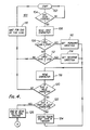
- Figures 4 and 5 show a routine associated with the decoding of the bar code bits and the generating of dialling signals respectively, i.e. the functions primarily performed by decoder 40 and encoder 70 in Figure 3.
- the scan routine 100 shown in Figure 4 shows a waiting loop of steps 102 and 104 which is continually cycling until the serial bits derived from the bar code are received.
- the first character (set of bar code bits) which should be an end code is read-in and stored at step 106.
- the character is then tested at step 108 to see if it is a start end code, indicating the number is being scanned in the forward direction. If so, a forward direction indicator or flag 110 is set. If the first character is not recognized as a start code, the flag 110 is not set and the code is tested at step 112 to see if it is a stop end code. If the latter is recognized a reverse direction flag 114 is set. If the character has not been recognized as a start or stop end code, i.e. not a valid code as has already been discussed, a "wait for end of scan instruction" is generated at step 116 to interrupt the input scan so that the remainder of the scan is ignored.
- the next character (which should be a set of five figure-representing bits) is entered and stored at step 118 the character bits being correctly oriented in the store in dependence on the direction flag.
- the character is verified at step 120, i.e. a correct 2-out-of-5 format, or a start or stop character, and if the character is invalid the wait instruction 116 is again generated. Assuming the character is verified it is checked at step 122 to see if it is a start or stop character, which will eventually appear when a scan is properly completed.
- a figure-representing character prior to that will pass to a decoding step 124 at where it is converted to a word or byte for storing in the addressable memory 62 of Figure 3.
- the storage of a character in the memory is signalled back to step 118 to indicate the next character may be entered for decoding.
- a dialling routine indicator or flag 126 is then set.
- the dialling routine 130 is illustrated in Figure 5 for an impulse dialling telephone system.
- the dialling routine commences upon receipt of the dialling routine flag 126.
- the first step 132 is to set up such conditions as need to be implemented to place dialling impulses on the telephone line. This is done with the aid of the interface circuit 80 of Figure 3.
- the next step 134 is to call the byte representing the first figure to be dialled from the memory 62. As discussed above, this will be the first figure of the telephone number having discarded if necessary any area prefix figures.
- the byte representing the figure is set up-step 136-as a corresponding count value in a counter, e.g. 72 in Figure 3.
- a dialling pulse generator e.g.
- step 138 whose parameters are in accord with the telephone network requirements, is activated at step 138 to place the first pulse on the external line via the interface.
- the counter is decremented by one (1) ⁇ step 140.
- a decision 142 is made to continue with the next dialling impulse as indicated by loop 144, and this procedure is repeated until zero count is detected.
- a decision 146 is made as to whether there are any further bytes in the memory to be dialled. If so, the routine calls up the next byte for dialling as indicated by loop 148. When the last figure has been fetched and dialled this is signalled at 149 to end the dialling procedure and wait a response to the automatically made call.
- Figures 6 to 8 show in general form arrangements of apparatus thus far described implemented with the aid of a microprocessor.
- the code-scanning wand 20 supplies the bar code pulse train to the microprocessor-based converter 150 which outputs dialling impulses to drive a standard d.c. signalling relay 152 that is in circuit with the telephone line to generate the required impulses on the line.
- Figure 7 shows an arrangement 160 for tone dialling, with a telephone having a manual keypad 162 for normal dialling.
- the wand 20 is again connected to a microprocessor 164 which in this case sends a digital word (byte) representing a number to be dialled on lines 166 to one 4-terminal input 170 of a selector device 168.
- the device has a second 4-terminal input 172 connected in conventional fashion over lines 174 to the output 176 of the key pad 162.
- the selector has a 4-terminal output 178 connected to transmit a byte present at input 172 or 174 to the input of a tone-generator device 180 which generates tones, for application to the external line.
- the selector device has a control input 182 the state of which (1 or 0) selects which input is connected to the tone generator.
- the control input is connected to the microprocessor 164 which normally holds the control input in the state connecting input 174 to the tone generator so that normal dialling is effected via the keypad. However, on detection of signals from wand 20, the control input state is changed to allow automatic dialling from the scanned bar code.
- the selector device 168 and tone generator 180 are standard items available as integrated circuits.
- devices 168 and 180 may be types SN74157 and ICM 7206 respectively available from Texas Instruments and Intersil.
- FIG. 8 shows an alternative arrangement for tone signalling.
- the keypad 162 is connected to an input port of microcomputer 190 which activates tone generator device 180 in dependence of receiving dialling input from the keypad or the wand 20.
- a code suitable for the purpose is hexadecimal coding, that is a coding to the base 16(2 4 1. This coding is much used in computer work and is readily expressed in terms of 4-bit bytes which in turn can be represented as bar codes. Hexadecimal represents decimal numbers 0-15 and in conformity with conventional notation, 0 to 9 (decimal) are represented by the figures 0-9 (hexadecimal) respectively while 10-15 are represented by the letters A to F respectively. Numbers represented in hexadecimal (hex.) will be identified by the suffix (H).
- Figure 9 shows a telephone number 02728081 represented as a bar code 200 for reading with a wand as already described with reference to Figure 3.
- the principles of reading and digitising the bar code are the same as before.
- a binary "1" is represented by a thick black bar: a "0” by a thin black bar, say a 3:1 thickness ratio with a light- colour (e.g. white) spacing in the form of representation shown.
- a 2-out-of-5 code contains an inherent figure-by-figure validation in its format. This is absent in the hex. equivalent.
- a "checksum" byte 202 is added between the left-hand end code 204 and the individual bar-coded figures of the telephone number which will be referred to as a whole as the digit field 206.
- the checksum byte is given a hex. value that makes the sum of the individual bytes of the digit field 206 and checksum byte 202 equal to zero (modulo 16).
- step 220 shows that a whole entry is recorded in an allocated memory space for validation. It will be noted that the total number of bits received including the 2-bit end codes has a value 0 modulo 4 in a correct entry.
- the first check is whether this conditions is satisfied. If not, a non-valid entry flag 224 is set and an appropriate display made to the user, e.g. via display 39 of Figure 3. If the bit count is satisfactory the end codes are detected, i.e. the two bits at either end are examined, at 226. In this case "00" and "10" are used for the left- and right-hand codes respectively and so there will be an end-code sequence 00 10 or 01 00.
- the sequence is not a valid one the non-valid entry flag 224 is set and the user display activated. If the sequence is valid it determines at step 228 the order, forward or reverse, in which the entry was made and a forward or reverse flag 230 or 232 respectively is set.
- the next validation step 234 is to sum the succession of 4-bit bytes constituted by the checksum byte 202 and digit field bytes 206. If the sum is not equal to 0 modulo 16, the non-valid flag 224 is set. Assuming the entry is valid the bytes of the digit field can be extracted for further processing 236. The position and order of the digit field in the memory space is known by reference to the set direction flag. The determination of the total number of bytes stored in memory and the extraction of them in the required sequence is done by employment of conventional procedures.
- the read-out of the bytes for dialling may be done as previously described including the discarding of the local area code such as "0272" in the number shown in Figure 9 which is for Bristol. Prior to dialling, the number could be displayed to the user as indicated at 238 to provide him with a visual check that the number is correct.
- Figure 8 enables the microcomputer to examine in accord with its programmed instructions dialled numbers, whether entered by the keypad or the wand, to ascertain whether they are allowed to be dialled from that extension.
- the instructions can only be entered via the wand.
- Figure 11 shows a representation of the format of an instruction bar code 250.
- the hex. code bar details are not illustrated.
- Each code position is shown as a box.
- the instruction code contains left-hand and right-hand blocks 204 and 208 as before and adjacent the left-hand block in accord with the format of Figure 9, there is a checksum byte 202.
- Next in sequence of the checksum position is a control byte position 252 and immediately following that is a function byte position 254.
- the control and function bytes are explained below.
- Following the function byte in a position immediately preceding the right-hand end code 208 (as in Figure 9) is a digit field 256.
- the digit field 256 is left blank for certain purposes and for convenience of layout and use can be omitted so that the right-hand end block is printed or otherwise reproduced adjacent the function byte.
- the bytes of the digit field are restricted to the numbers 0-9 (H) and the checksum byte 202 may take any value from 0F(H).
- the control byte is restricted to values in the range A to F (H) thereby enabling the presence of a control byte to be clearly distinguished from figures.
- the function byte may take a value in the range 0-F(H) but it is only present in combination with one or more selected control byte values. Thus a function byte of a value in the range 0-9 (H) can be distinguished from the digit field by its byte position immediately following a control byte having a value that requires a function byte to supplement it.
- the further processing of the bytes is illustrated in the flow chart of Figure 12 in which the bytes extracted to the right of the checksum byte (the bytes in the dashed-line rectangle) are shown as entering at 260.
- the chart shows the first step 262 to check whether the first byte received has a value in the range A-F (H). If so this byte is identified as a control byte (C-byte).
- the next step 264 shown separately for convenience is to decide whether the specific control byte has a value requiring a function byte (F-byte) to complete the instruction. If so the next byte is acted upon as a function byte as indicated at 266.
- the next step 268 is to decide whether the instruction represented by the control byte alone or by the combination of control and function bytes is one requiring numerical information. If so, step 270 indicates that the next byte or bytes in sequence will be the relevant numerical data. The next byte will be the second or third byte depending on whether or not a function byte is required.
- the microcomputer then acts at step 272 to store the complete instruction represented by the instruction code at step 274 or in certain cases to first await a following instruction at step 276. This generalisation of the procedure may be better understood with reference to the examples given below.
- dialling of any number beginning with "0" may be disabled (disallowed) except, possibly, for the the local area dialling code which, if present, is to be stripped from the number before dialling.
- dialling anywhere in the United Kingdom may be allowed but not international dialling. In this case, the examination procedure would look at the first three figures to ascertain if they were "010" and, if so, disable dialling.
- Bytes 1, 2, 5, 6, 9 and A(H) are complete instructions. Bytes 0, 3 and 4(H) require all further instruction to follow. Bytes 7 and 8(H) concern a facility that will be further discussed below.
- Byte 1(H) will prevent dialling of any number including an area or international code as would be required for calls outside the local area.
- Byte 2(H) disables international dialling only.
- Bytes 5 and 6(H) are predicated on the basis that certain telephone numbers may be stored in the memory of the microcomputer and may be treated as a group as regards their allowability or disallowability for dialling.
- a group could include, for example, selected non-local numbers. Up to sixteen separate groups may be readily accommodated in the present system.
- Bytes 9 and A(H) could be used in the selective restriction of a particular extension to dialling internal extension numbers only.
- Bytes 0, 3 and 4(H) are used in conjunction with byte 8(H).
- the "pad” referred to provides a means of reading in a local area code, e.g. 01; 0272 for London and Bristol respectively in the United Kingdom. As already mentioned, the pad itself is described later.
- control byte B(H) this is used to indicate that what follows in the digit field is a telephone number that is to be stored within the microcomputer memory and that it pertains to one of the groups already mentioned above.
- the function byte contains the designation 0-F(H) of the group to which the number is to be allocated. This enables numbers to be stored in up to sixteen groups.
- the C(H) value of the control byte is used in conjunction with the entry of a single figure from the pad and is intended to indicate that just the one figure is to be expected.
- control byte F(H) is used without a function byte to indicate that the complete telephone number present in the digit field is always to be available for dialling. For example, the emergency services number "999".
- step 278 in Figure 12 the microcomputer will first check whether a number entered falls within the final classification.
- the order in which the other enable/disable instructions are checked will depend on how many of the functions it is desired to implement and the priority. Modern microprocessor devices are capable of operating so rapidly that no significant delay is apparent to the user.
- the codes covered by the first line-control byte A(H)-of the above Table can be set out, as by printing, one by one on a suitable support medium with the appropriate labelling. As previously pointed out the bar codes may be printed on adhesive labels. Each code is set out with the format exemplified by Figure 11 and in accord with the tabulated requirements. Codes formed according to the second and third line (control bytes B(H) and F(H) can be likewise set out. The support media containing these codes would be made available only to authorized persons. Consequently the microcomputer of a telephone extension equipped as illustrated by Figure 8 would be selectively instructable and those instructions would not be alterable by the ordinary user.
- the pad that has already been mentioned may take the form illustrated in Figure 13 in which a support medium 290 is shown as having a plurality of adhesive printed labels 292 adhered to it, the medium and labels being preferable overlain by a clear sheet for protection.
- the pad contains labels arranged rather as a keyboard for the values 0 to 9 with another label for the ENTER or EXECUTE instruction.
- the support medium bears the appropriate legend adjacent each label.
- Each label is imprinted with the value of the associated number in a prescribed format.
- Figure 14 shows a label to a larger scale to illustrate the format. The format is that discussed with reference to Figure 11 using the instruction C(H) for the control byte 252. This byte is preceded by the lefthand end code 204 and checksum 252 respectively.
- the microcomputer is programmed to hold the single figure entries until an entry instruction code is given.
- the ENTRY instruction can be given by having the enter label use the same format as the figure labels but having a specified hexadecimal code in the range A to F(H) which is a combination recognized as an ENTRY instruction.
- the use of the pad may be further explained by assuming that, as already mentioned, there exist pre-printed labels in accord with the sequence of instructions represented by the combination of control byte A(H) and the series of function bytes 0 to A(H).
- the label for this function which includes combination A(H) ⁇ 0(H)
- the area code-say 0272 for Bristol-is entered by scanning in succession the labels corresponding to 0: 2: 7: 2: ENTER (the colons are inserted to clearly separate the successive labels scanned).
- the ENTER at the end is an instruction that the particular operation is completed.
- an initial instruction label might be that associated with groups so that the function byte position has the value 3 or 4(H).
- the pad is used to enter the number of the group, and the procedure terminated by an ENTER scan.
- ENTER scan the procedure terminated by an ENTER scan.
- the user will naturally think in terms of groups "10" to "15” rather than A(H) to F(H). Consequently, a group in the range "0" to "9” is selected by scanning the number label on the pad followed by ENTER.
- a group such as "14” is selected by scanning the 1:4: ENTER labels in that sequence the microcomputer tranlating this entry to E(H).
- pad may contain the emergency services number "999" that is always to be
- Figure 15 is in accord with Figure 11 containing in succession lefthand end code 204, checksum byte (value 6(H) in this case) 202, control byte F(H) 252, a three figure digit field 256 and the righthand end code block 208.
- the function byte 254 is not required in this case.
- a group number using the control byte B(H) would have a similar format but with the insertion of a function byte 254 between the control byte 252 and digit field 256 and the digit field would contain the full number.
- FIG. 16 diagrammatically shows a dot-matrix printer 300 with a head 302 traversing a printing medium 304 on a support platen 306.
- the dot-matrix head normally prints by selective actuation of a vertical array of needles in a multi-step transverse movement forming a single character.
- a column of seven needles is commonly used in a five step movement (7x5 array) though more array dot elements are often provided.
- a "0" value bar can be printed by means of actuating the whole needle array to form a line stroke character, that is the "0" bar. This provides a single vertical line that is continuous as far as the resolution of a scanning wand is concerned.
- a "1" value is printed by activating the needle array three times in immediate succession in a single character. The line strokes effectively merge in the transverse direction as seen by the optical head.
- the characters 0-9 and A-H are input from a keyboard 310.
- An interface 312 receives the character codes, e.g. in ASCII, and translates them to corresponding hexadecimal code or the keyboard could be specifically adapted to provide the characters already hexadecimally encoded.
- the interface contains the means to activate the printer head according to each hexadecimally coded input character. For a purpose-built printer this could be a customized ROM.
- comb printer which comprises a line array (comb of electrodes) that is held stationary while the printing medium is moved beneath it, usually in steps.
- line array comb of electrodes
- needle array or comb could be substituted by any printing element activatable to print a line stroke.
- dialling is performed more quickly than pulse dialling.
- the latter normally provides adequate intervals for the telephone exchange to register and process the dialled number.
- One pause may for example be inserted between an international code and the remainder of the number.
- Such a pause could actually be inserted in a coded number represented as in Figure 11 by inserting say the unused value D(H) as an element in the digit field to represent a pause, or, to conserve space, a special bar width say four times the width of a "0" value bar, may be inserted. (This special bar would be excluded from any checksum calculation).
Landscapes
- Engineering & Computer Science (AREA)
- Signal Processing (AREA)
- External Artificial Organs (AREA)
- Telephone Function (AREA)
- Telephone Set Structure (AREA)
- Telephonic Communication Services (AREA)
- Input From Keyboards Or The Like (AREA)
- Mobile Radio Communication Systems (AREA)
Claims (9)
Priority Applications (1)
| Application Number | Priority Date | Filing Date | Title |
|---|---|---|---|
| AT82303728T ATE22639T1 (de) | 1981-07-17 | 1982-07-15 | Fernsprechwaehlsystem. |
Applications Claiming Priority (2)
| Application Number | Priority Date | Filing Date | Title |
|---|---|---|---|
| GB8122132 | 1981-07-17 | ||
| GB8122132 | 1981-07-17 |
Publications (3)
| Publication Number | Publication Date |
|---|---|
| EP0070697A2 EP0070697A2 (fr) | 1983-01-26 |
| EP0070697A3 EP0070697A3 (en) | 1983-06-01 |
| EP0070697B1 true EP0070697B1 (fr) | 1986-10-01 |
Family
ID=10523320
Family Applications (1)
| Application Number | Title | Priority Date | Filing Date |
|---|---|---|---|
| EP82303728A Expired EP0070697B1 (fr) | 1981-07-17 | 1982-07-15 | Système d'appel téléphonique |
Country Status (4)
| Country | Link |
|---|---|
| US (1) | US4535204A (fr) |
| EP (1) | EP0070697B1 (fr) |
| AT (1) | ATE22639T1 (fr) |
| DE (1) | DE3273565D1 (fr) |
Cited By (1)
| Publication number | Priority date | Publication date | Assignee | Title |
|---|---|---|---|---|
| DE4336791C1 (de) * | 1993-10-28 | 1994-11-10 | Grundig Emv | Verfahren zur Auswahl einer Rufnummer aus einem Rufnummernspeicher |
Families Citing this family (40)
| Publication number | Priority date | Publication date | Assignee | Title |
|---|---|---|---|---|
| US5153906A (en) * | 1983-11-11 | 1992-10-06 | Nippo Communication Industrial Co., Ltd. | Personal-servicing communication system |
| CA1222586A (fr) * | 1983-11-11 | 1987-06-02 | Tadahiko Akiyama | Systeme de communication offrant des services personnels |
| GB8500071D0 (en) * | 1985-01-03 | 1985-02-13 | Varley T | Telephone equipment |
| US4680457A (en) * | 1985-03-07 | 1987-07-14 | Telesis Controls Corporation | Code reader |
| DE3510289A1 (de) * | 1985-03-19 | 1986-10-02 | Krone Gmbh, 1000 Berlin | Wahlhilfezusatz fuer fernsprechapparate |
| JP2564480B2 (ja) * | 1985-07-16 | 1996-12-18 | カシオ計算機株式会社 | Icカ−ドシステム |
| US4817136A (en) * | 1987-08-17 | 1989-03-28 | Rhoads Richard M | Telephone dialing system |
| EP0317496B1 (fr) * | 1987-09-14 | 1993-02-24 | Ascom Autophon Ag | Poste téléphonique pourvu d'un répertoire d'abonnés |
| US4817135A (en) * | 1987-11-24 | 1989-03-28 | U.S. News Limited Partnership | CRT mass-distribution, preprogrammed automatic dialing mechanism and related processes |
| DE3741788C2 (de) * | 1987-12-10 | 1995-02-16 | Telefonbau & Normalzeit Gmbh | Fernsprechapparat mit einer Sendeeinrichtung |
| US4897865A (en) * | 1988-04-29 | 1990-01-30 | Epic Data, Inc. | Telephone data collection device |
| US5165726A (en) * | 1988-09-06 | 1992-11-24 | Talbott Alex F | Mailing device and business card combination |
| US5232248A (en) * | 1988-09-06 | 1993-08-03 | Talbott Alex F | Mailing device |
| US4945218A (en) * | 1988-09-06 | 1990-07-31 | Talbott Alex F | Mailing device and machine-readable business card |
| US4937853A (en) * | 1989-05-03 | 1990-06-26 | Agt International, Inc. | Lottery agent data communication/telephone line interface |
| US4975948A (en) * | 1989-10-13 | 1990-12-04 | Andresen Dennis R | Rapid dialing method for telecommunications |
| FR2653288A1 (fr) * | 1989-10-17 | 1991-04-19 | Hout Suzanne | Dispositif telephonique permettant la numerotation automatique a partir de la lecture optique de numeros de telephone imprimes ou manuscrits. |
| KR930002383B1 (ko) * | 1989-12-29 | 1993-03-29 | 주식회사 일진 | 차량 검색 시스템 |
| JPH03218149A (ja) * | 1990-01-24 | 1991-09-25 | Nec Corp | 携帯無線電話機 |
| GB2246491B (en) * | 1990-07-26 | 1994-09-14 | Technophone Ltd | Telephone with bar code reader |
| US5313642A (en) * | 1990-10-03 | 1994-05-17 | Seagull Scientific Systems, Inc. | Power interface for peripheral devices |
| US5210790A (en) * | 1991-02-08 | 1993-05-11 | Winbond Electronics Corp. | Device for setting and tone dialing a single telephone number |
| US5288976A (en) * | 1991-07-15 | 1994-02-22 | Nynex Corporation | Bar code use in information, transactional and other system and service applications |
| SE468966B (sv) * | 1991-08-30 | 1993-04-19 | Ericsson Telefon Ab L M | Foerfarande foer att underlaetta vaexling mellan anvaendning av mobilstation och fast telefon |
| US5256865A (en) * | 1991-11-05 | 1993-10-26 | Ncr Corporation | Automatic sensing and programming circuit and programming method for optical scanners |
| IT1254650B (it) * | 1992-02-28 | 1995-09-28 | Rimoldi Srl | Metodo e scheda di lavoro per l'impostazione di cicli operativi di unita' elettroniche di governo di macchine per cucire |
| US5640447A (en) * | 1993-08-30 | 1997-06-17 | Fonseca; David | Debit calling label |
| US5701591A (en) * | 1995-04-07 | 1997-12-23 | Telecommunications Equipment Corporation | Multi-function interactive communications system with circularly/elliptically polarized signal transmission and reception |
| GB2300498A (en) * | 1995-05-05 | 1996-11-06 | Steve Mccauley | Entering data into electronic personal organisers |
| US6098882A (en) | 1996-03-01 | 2000-08-08 | Cobblestone Software, Inc. | Variable formatting of digital data into a pattern |
| US6820807B1 (en) * | 1996-03-01 | 2004-11-23 | Cobblestone Software, Inc. | Variable formatting of digital data into a pattern |
| US6212401B1 (en) * | 1996-12-24 | 2001-04-03 | Intermec Corporation | Data acquisition using telephone connection |
| US7054657B2 (en) * | 2000-02-17 | 2006-05-30 | Nokia Corporation | Backwards compatible, extended method to execute check number calculation of IMEI |
| GB2359956A (en) * | 2000-03-03 | 2001-09-05 | Michael Andrew George | Easy dial telephone |
| US20020111869A1 (en) * | 2001-01-16 | 2002-08-15 | Brian Shuster | Method and apparatus for remote data collection of product information using a communications device |
| US6729537B2 (en) * | 2001-07-27 | 2004-05-04 | Agere Systems Inc. | System and method for automating telecommunications session initiation and calling card for use therewith |
| US7502459B1 (en) * | 2002-02-28 | 2009-03-10 | Adaptec, Inc. | Unified services entitlement architecture |
| US7905409B2 (en) * | 2005-05-20 | 2011-03-15 | Senshin Capital, Llc | Print medium feature encoding and decoding |
| SE532740C2 (sv) * | 2006-12-15 | 2010-03-30 | Mobill Scandinavia Ab | Metod och apparat för att skapa och skicka ett kodat rutnät till en portabel kommunikationsanordning |
| US20140372469A1 (en) * | 2013-06-14 | 2014-12-18 | Walter Gerard Antognini | Searching by use of machine-readable code content |
Family Cites Families (5)
| Publication number | Priority date | Publication date | Assignee | Title |
|---|---|---|---|---|
| US3735350A (en) * | 1966-02-10 | 1973-05-22 | J Lemelson | Code scanning system |
| US3987278A (en) * | 1972-10-18 | 1976-10-19 | The Gleason Works | Moving object identifying system |
| US4042792A (en) * | 1973-10-25 | 1977-08-16 | The General Electric Company Limited | Telephone subscriber's apparatus for signalling decimal digit values represented in printed form |
| US4105997A (en) * | 1977-01-12 | 1978-08-08 | United States Postal Service | Method for achieving accurate optical character reading of printed text |
| US4349741A (en) * | 1980-10-20 | 1982-09-14 | International Business Machines Corporation | Ear code with alignment mark |
-
1982
- 1982-07-15 DE DE8282303728T patent/DE3273565D1/de not_active Expired
- 1982-07-15 AT AT82303728T patent/ATE22639T1/de not_active IP Right Cessation
- 1982-07-15 EP EP82303728A patent/EP0070697B1/fr not_active Expired
- 1982-07-16 US US06/398,803 patent/US4535204A/en not_active Expired - Fee Related
Cited By (1)
| Publication number | Priority date | Publication date | Assignee | Title |
|---|---|---|---|---|
| DE4336791C1 (de) * | 1993-10-28 | 1994-11-10 | Grundig Emv | Verfahren zur Auswahl einer Rufnummer aus einem Rufnummernspeicher |
Also Published As
| Publication number | Publication date |
|---|---|
| DE3273565D1 (en) | 1986-11-06 |
| EP0070697A2 (fr) | 1983-01-26 |
| US4535204A (en) | 1985-08-13 |
| EP0070697A3 (en) | 1983-06-01 |
| ATE22639T1 (de) | 1986-10-15 |
Similar Documents
| Publication | Publication Date | Title |
|---|---|---|
| US4535204A (en) | Telephone dialling system | |
| US4021777A (en) | Character reading techniques | |
| EP0278169B1 (fr) | Système pour l'entrée de données dans un ordinateur | |
| US4907264A (en) | Telephone set with subscriber listing | |
| US4091270A (en) | Electronic calculator with optical input means | |
| US5557092A (en) | Apparatus and method for 16-bit and numeric data collection using bar code symbologies | |
| US4500872A (en) | Method for encoding Chinese characters | |
| US4804279A (en) | Real-time word typewriter | |
| EP0390162A2 (fr) | Appareil de lecture de code barre | |
| SE420447B (sv) | Metod for generering av teckenkoder medelst ett tangentbord samt anordning for utforande av metoden | |
| US4727511A (en) | Multitype characters processing method and terminal device | |
| CA1123360A (fr) | Methode de composition de textes en caracteres arabes, et dispositif connexe | |
| USRE29104E (en) | Method of scanning documents to read characters thereon without interference from visible marks on the document which are not to be read by the scanner | |
| US3820067A (en) | Character reading system controlled by preprinted program control characters on document form | |
| KR860001012B1 (ko) | 표의문자 코딩장치 | |
| WO1995012863A1 (fr) | Appareil et procede de collecte de donnees numeriques et a 16 bits utilisant les symbolisations par codes a barres | |
| US4695828A (en) | Electronic apparatus for entering pattern data by finger activation | |
| US4482981A (en) | Input device for pocket electronic translator | |
| KR100555431B1 (ko) | 문자 표시장치 및 문자 입력장치 | |
| JPS5932829B2 (ja) | 文字読取り方法 | |
| KR950003479B1 (ko) | 팩시밀리의 인식명 등록방법 | |
| KR0164404B1 (ko) | 소수의 전화버튼을 이용한 문자 제어방법 및 장치 | |
| EP0397111A2 (fr) | Dispositif d'affichage avec rapports entre les codes de caractères et les caractères affichés definis par l'utilisateur | |
| JPH11338964A (ja) | 情報コード読取作成装置 | |
| KR100260904B1 (ko) | 잉크젯 복합기의 독립적인 상태에서의 인쇄 수직 정렬 방법 |
Legal Events
| Date | Code | Title | Description |
|---|---|---|---|
| PUAI | Public reference made under article 153(3) epc to a published international application that has entered the european phase |
Free format text: ORIGINAL CODE: 0009012 |
|
| AK | Designated contracting states |
Designated state(s): AT BE CH DE FR GB IT LI LU NL SE |
|
| PUAL | Search report despatched |
Free format text: ORIGINAL CODE: 0009013 |
|
| AK | Designated contracting states |
Designated state(s): AT BE CH DE FR GB IT LI LU NL SE |
|
| 17P | Request for examination filed |
Effective date: 19831201 |
|
| GRAA | (expected) grant |
Free format text: ORIGINAL CODE: 0009210 |
|
| AK | Designated contracting states |
Kind code of ref document: B1 Designated state(s): AT BE CH DE FR GB IT LI LU NL SE |
|
| PG25 | Lapsed in a contracting state [announced via postgrant information from national office to epo] |
Ref country code: NL Effective date: 19861001 Ref country code: LI Effective date: 19861001 Ref country code: IT Free format text: LAPSE BECAUSE OF FAILURE TO SUBMIT A TRANSLATION OF THE DESCRIPTION OR TO PAY THE FEE WITHIN THE PRESCRIBED TIME-LIMIT;WARNING: LAPSES OF ITALIAN PATENTS WITH EFFECTIVE DATE BEFORE 2007 MAY HAVE OCCURRED AT ANY TIME BEFORE 2007. THE CORRECT EFFECTIVE DATE MAY BE DIFFERENT FROM THE ONE RECORDED. Effective date: 19861001 Ref country code: CH Effective date: 19861001 Ref country code: BE Effective date: 19861001 Ref country code: AT Effective date: 19861001 |
|
| REF | Corresponds to: |
Ref document number: 22639 Country of ref document: AT Date of ref document: 19861015 Kind code of ref document: T |
|
| PG25 | Lapsed in a contracting state [announced via postgrant information from national office to epo] |
Ref country code: SE Effective date: 19861031 |
|
| REF | Corresponds to: |
Ref document number: 3273565 Country of ref document: DE Date of ref document: 19861106 |
|
| RAP2 | Party data changed (patent owner data changed or rights of a patent transferred) |
Owner name: LHW TELEPHONE AUTO DIALERS LIMITED |
|
| ET | Fr: translation filed | ||
| REG | Reference to a national code |
Ref country code: CH Ref legal event code: PL |
|
| NLV1 | Nl: lapsed or annulled due to failure to fulfill the requirements of art. 29p and 29m of the patents act | ||
| PLBE | No opposition filed within time limit |
Free format text: ORIGINAL CODE: 0009261 |
|
| STAA | Information on the status of an ep patent application or granted ep patent |
Free format text: STATUS: NO OPPOSITION FILED WITHIN TIME LIMIT |
|
| PG25 | Lapsed in a contracting state [announced via postgrant information from national office to epo] |
Ref country code: LU Free format text: LAPSE BECAUSE OF NON-PAYMENT OF DUE FEES Effective date: 19870731 |
|
| 26N | No opposition filed | ||
| PGFP | Annual fee paid to national office [announced via postgrant information from national office to epo] |
Ref country code: GB Payment date: 19920715 Year of fee payment: 11 |
|
| PGFP | Annual fee paid to national office [announced via postgrant information from national office to epo] |
Ref country code: DE Payment date: 19920824 Year of fee payment: 11 |
|
| PGFP | Annual fee paid to national office [announced via postgrant information from national office to epo] |
Ref country code: FR Payment date: 19920827 Year of fee payment: 11 |
|
| PG25 | Lapsed in a contracting state [announced via postgrant information from national office to epo] |
Ref country code: GB Effective date: 19930715 |
|
| GBPC | Gb: european patent ceased through non-payment of renewal fee |
Effective date: 19930715 |
|
| PG25 | Lapsed in a contracting state [announced via postgrant information from national office to epo] |
Ref country code: FR Effective date: 19940331 |
|
| PG25 | Lapsed in a contracting state [announced via postgrant information from national office to epo] |
Ref country code: DE Effective date: 19940401 |
|
| REG | Reference to a national code |
Ref country code: FR Ref legal event code: ST |