EP0070814B1 - Dispositif de compensation de la tension lors du bobinage dans les machines textiles - Google Patents
Dispositif de compensation de la tension lors du bobinage dans les machines textiles Download PDFInfo
- Publication number
- EP0070814B1 EP0070814B1 EP19820830206 EP82830206A EP0070814B1 EP 0070814 B1 EP0070814 B1 EP 0070814B1 EP 19820830206 EP19820830206 EP 19820830206 EP 82830206 A EP82830206 A EP 82830206A EP 0070814 B1 EP0070814 B1 EP 0070814B1
- Authority
- EP
- European Patent Office
- Prior art keywords
- sliver
- bobbin
- compensator device
- compensator
- fact
- Prior art date
- Legal status (The legal status is an assumption and is not a legal conclusion. Google has not performed a legal analysis and makes no representation as to the accuracy of the status listed.)
- Expired
Links
- 238000004804 winding Methods 0.000 title claims description 14
- 239000004753 textile Substances 0.000 title description 3
- 239000011295 pitch Substances 0.000 description 3
- 229910000639 Spring steel Inorganic materials 0.000 description 1
- 229910000831 Steel Inorganic materials 0.000 description 1
- 230000015572 biosynthetic process Effects 0.000 description 1
- 238000010276 construction Methods 0.000 description 1
- 239000002184 metal Substances 0.000 description 1
- 239000007787 solid Substances 0.000 description 1
- 239000010959 steel Substances 0.000 description 1
Images


Classifications
-
- B—PERFORMING OPERATIONS; TRANSPORTING
- B65—CONVEYING; PACKING; STORING; HANDLING THIN OR FILAMENTARY MATERIAL
- B65H—HANDLING THIN OR FILAMENTARY MATERIAL, e.g. SHEETS, WEBS, CABLES
- B65H57/00—Guides for filamentary materials; Supports therefor
- B65H57/12—Tubes
-
- B—PERFORMING OPERATIONS; TRANSPORTING
- B65—CONVEYING; PACKING; STORING; HANDLING THIN OR FILAMENTARY MATERIAL
- B65H—HANDLING THIN OR FILAMENTARY MATERIAL, e.g. SHEETS, WEBS, CABLES
- B65H59/00—Adjusting or controlling tension in filamentary material, e.g. for preventing snarling; Applications of tension indicators
- B65H59/005—Means compensating the yarn tension in relation with its moving due to traversing arrangements
-
- B—PERFORMING OPERATIONS; TRANSPORTING
- B65—CONVEYING; PACKING; STORING; HANDLING THIN OR FILAMENTARY MATERIAL
- B65H—HANDLING THIN OR FILAMENTARY MATERIAL, e.g. SHEETS, WEBS, CABLES
- B65H2701/00—Handled material; Storage means
- B65H2701/30—Handled filamentary material
- B65H2701/31—Textiles threads or artificial strands of filaments
- B65H2701/311—Slivers
Definitions
- This invention concerns a compensator device for the carriage that winds bobbins in textile machines with one or more bobbins, said device being suitable for enabling the sliver leaving a drawing frame or derived machine to be taken up.
- the main object of the invention is to provide a compensator device able to convey, and maintain a constant length of the sliver between the exit of the drawing frame or derived machine and the intake of the sliver itself by the revolving funnel of the traversing carriage that winds bobbins.
- Our invention fulfils its purpose of guiding the sliver along an obligatory path of an always constant length with a compensator device of flexible nature which is of simpler and more solid construction than the known devices and which also enables the length of the path between the delivery point and the take-up spindle to be kept as short as possible.
- the present invention relates to a compensator device known from BE-A-659089 and consisting of a sliver flexible support arranged in a bow- shape and flexibly anchored at one end to the exit of the drawing frame delivery calender and at its other end to the bobbin-winding carriage transversing along theyarn bobbin being formed, along which flexible support the sliver is constrained to run at a constant arc length.
- the compensator device consists essentially of a spring wire wound in coils with a spiral having its diameter and coil pitch differentiated in at leastthree different tracts, whereby the compensator is anchored at one end to the exit of the drawing frame calender and at its other end to the bobbin-winding carriage transversing along the yarn package being formed and whereby the sliver runs inside said coils.
- the spirals of the first and last tracts have greater coil pitch and smaller diameter as compared to the middle tract and have the task of guiding the sliver and the additional task of imparting a false twist to it at the same time.
- one of the spirals or both the spirals of the first and last tracts impart to the sliver a false twist which runs in the reverse direction in respect of the feed of the sliver itself.
- the compensator device of this embodiment has the low inertia needed to resist the fatigue stress generated by its alternating movement in winding the yarn package.
- An advantage provided by the compensator device of this embodiment lies in the fact that its low inertia facilitates the rapid alternating movement of the bobbin-winding carriage.
- the inlet of the compensator device is secured to the drawing frame or like machine with appendages which are clamped downstream from the calender and the outlet of the compensator device is secured to the bobbin-winding carriage with an appendage of the sliver exit guide.
- the inlet consists of two closed coils which have the task of giving necessary elasticity for the alternating movement of the compensator device, which swings and pivots on said coils in the vertical and horizontal planes.
- the actual length of the compensator device does not vary with the variation of the position of the bobbin-winding carriage and therefore the length of the sliver running within the compensator device remains strictly constant, thus leading to perfect compensation.
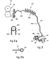
- the sliver flexible support 120 of this embodiment consists of spring wire wound in coils with a plurality of tracts of spirals having differentiated diameters and coil pitches.
- the flexible support 120 consists essentially of spring steel wire wound in coils and stretching from the drawing frame 12 to the bobbin-winding carriage 18; said wire has a first tract 210 with coils spaced widely apart, a middle tract 310 acting as an elbow and having coils close together and with a larger diameter than the first tract 210, and a last tract 410 with coils spaced widely apart and a smaller diameter than the middle tract 310.
- Anchorage means 30 and 31 respectively are envisaged at each end of the coiled wire and have the task of securing the inlet head 11 to the support 122 of the drawing frame 12 and the outlet end 13 to the bobbin-winding carriage 18.
- Said anchorage means 30, 31 are solidly fixed to the relative end portions 11, 13 of the coiled wire, and said end portions 11, 13 respectively consist advantageously of a number of coils acting as an articulated joint and as a sliver guide at the inlet and outlet of the wire.
- the end portion at the inlet 11 consists of two closed coils side by side 201 which have the task of providing the necessary elasticity for the alternating movement of the compensator device 110, which swings and pivots on the end coils 201 in the vertical and horizontal planes, whereby said two closed coils 201 are provided with appendages 130 that constitute the anchorage means 30 of Fig. 3a clamped to the support 122 of the drawing frame 12.
- the outlet end portion 13 consists likewise of a closed coil 211 having an appendage 131 which constitutes the anchorage means and cooperates with a joint 132 mounted on ball bearings located on the bobbin-winding carriage 18.
- the coils of the first tract 210 and/or last tract 410 can advantageously but not necessarily be wound in opposite directions such as to impart to the sliver 112 in the first tract a false twist that runs in the reverse direction in respect of the feed of the sliver 122 itself and to take away same in the last tract 410.
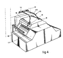
- Fig. 4 shows a machine to which are fitted two compensator devices 110, according to the preferred embodiment, each of which serves a winding station located at the side of the machine.
- the wire may consist of another suitable metal; it is possible to conform and fit the anchorage elements 30 and 31 differently without departing thereby from the scope of the invention.
Landscapes
- Engineering & Computer Science (AREA)
- Textile Engineering (AREA)
- Spinning Or Twisting Of Yarns (AREA)
Claims (5)
Applications Claiming Priority (4)
| Application Number | Priority Date | Filing Date | Title |
|---|---|---|---|
| IT8343781 | 1981-07-20 | ||
| IT8183437A IT8183437A0 (it) | 1981-07-20 | 1981-07-20 | Dispositivo per uscita a bobine di stiratoio per fibre tessili. |
| IT83322/82A IT1158066B (it) | 1982-02-10 | 1982-02-10 | Dispositivo compensatore per carro bobinatore nelle macchine tessili |
| IT8332282 | 1982-02-10 |
Publications (2)
| Publication Number | Publication Date |
|---|---|
| EP0070814A1 EP0070814A1 (fr) | 1983-01-26 |
| EP0070814B1 true EP0070814B1 (fr) | 1986-09-24 |
Family
ID=26330050
Family Applications (1)
| Application Number | Title | Priority Date | Filing Date |
|---|---|---|---|
| EP19820830206 Expired EP0070814B1 (fr) | 1981-07-20 | 1982-07-12 | Dispositif de compensation de la tension lors du bobinage dans les machines textiles |
Country Status (3)
| Country | Link |
|---|---|
| EP (1) | EP0070814B1 (fr) |
| AU (1) | AU8554382A (fr) |
| DE (1) | DE3273451D1 (fr) |
Families Citing this family (6)
| Publication number | Priority date | Publication date | Assignee | Title |
|---|---|---|---|---|
| WO1987007882A1 (fr) * | 1986-06-20 | 1987-12-30 | Tashkentskoe Spetsialnoe Konstruktorskoe Bjuro Tex | Dispositif de depot d'un materiau filamenteux |
| IT1205058B (it) * | 1987-06-19 | 1989-03-10 | Savio Spa | Dispositivo torsionatore per carro bobinatore |
| IT1205059B (it) * | 1987-06-19 | 1989-03-10 | Savio Spa | Elemento a spirale per impartire compensazione e falsa torsione ai nastri di fibre tessili |
| IT1223533B (it) * | 1987-12-18 | 1990-09-19 | Savio Spa | Elemento a spirale rotante per impartire compensazione e falsa torsione ai nastri di fibre tessili |
| IT1223525B (it) * | 1987-12-18 | 1990-09-19 | Savio Spa | Dispositivo torsionatore con spirale rotante per carro bobinatore |
| CN120308754B (zh) * | 2025-06-18 | 2025-09-02 | 湖南宏力纺织有限公司 | 一种纺纱绕线设备 |
Family Cites Families (8)
| Publication number | Priority date | Publication date | Assignee | Title |
|---|---|---|---|---|
| US2442817A (en) * | 1944-12-21 | 1948-06-08 | Jack B Lyle | Guide for running flexible material |
| DE1059321B (de) * | 1957-10-15 | 1959-06-11 | Chr Mann Maschinenfabrik | Beweglicher Bandfuehrer zum Wickeln von Kreuzspulen an Strecken oder Vorspinnmaschinen |
| GB883609A (en) * | 1960-03-16 | 1961-12-06 | Herbert Steinwandt | Movable sliver guide for winding cross-wound bobbins on draw frames or slubbing machines |
| CH427589A (de) * | 1964-03-09 | 1966-12-31 | Reiter Michael | Beweglicher Band- oder Vorgarnführer zum Herstellen von Kreuzwickeln |
| BE659089A (fr) * | 1965-01-29 | |||
| US3518733A (en) * | 1967-11-06 | 1970-07-07 | Techniservice Corp | Strand treatment |
| US3670978A (en) * | 1970-10-02 | 1972-06-20 | Warner Swasey Co | Compensator device |
| GB1512373A (en) * | 1974-07-25 | 1978-06-01 | Gilchrist R | Yarn twisting device |
-
1982
- 1982-07-02 AU AU85543/82A patent/AU8554382A/en not_active Abandoned
- 1982-07-12 EP EP19820830206 patent/EP0070814B1/fr not_active Expired
- 1982-07-12 DE DE8282830206T patent/DE3273451D1/de not_active Expired
Also Published As
| Publication number | Publication date |
|---|---|
| DE3273451D1 (en) | 1986-10-30 |
| EP0070814A1 (fr) | 1983-01-26 |
| AU8554382A (en) | 1983-01-27 |
Similar Documents
| Publication | Publication Date | Title |
|---|---|---|
| JP5156401B2 (ja) | 巻取機 | |
| CN101377026A (zh) | 纱线卷绕机及假捻加工机 | |
| KR19990087402A (ko) | 얀의 정방 또는 트위스트 공정에서의 실끊김의 감소 | |
| EP0070814A1 (fr) | Dispositif de compensation de la tension lors du bobinage dans les machines textiles | |
| US6869004B2 (en) | High-speed fiber feed assembly | |
| US1966507A (en) | Machine for winding yarn thread and the like | |
| US4862687A (en) | Spinning system having a rotary balloon checking device | |
| US4202161A (en) | Apparatus for producing novelty yarn | |
| EP0295731B1 (fr) | Dispositif pour produire une fausse torsion à un ruban de fibres textiles | |
| US3452531A (en) | Yarn severing device on a spinning machine stop motion | |
| JPS62206028A (ja) | 互いに撚り合わされる糸成分の事前強化装置 | |
| CN106460252B (zh) | 纺纱准备机 | |
| US2796225A (en) | Thread tensioning apparatus for twisting spindles | |
| CN106460248B (zh) | 纺纱准备机 | |
| RU2124596C1 (ru) | Способ получения армированной нити с металлосодержащим сердечником | |
| EP0295733A1 (fr) | Guide en spirale pour fils textiles pour compenser une torsion à l'envers | |
| EP0321011B1 (fr) | Tordeur avec spirale rotative pour les machines textiles lors du bobinage | |
| US1297495A (en) | Spooler. | |
| US5222677A (en) | Apparatus and method for the drawing off of threads, ribbons and the like | |
| EP0321034B1 (fr) | Elément spiral rotatif pour répartir la compensation de la tension et la fausse torsion dans une mèche textile | |
| JP4175690B2 (ja) | 弾性フィラメント糸の巻き取り装置 | |
| US245856A (en) | A tvttvxt tra | |
| JPH0242927B2 (fr) | ||
| SU1097733A1 (ru) | Устройство дл прокладывани уточной нити на пневморапирном ткацком станке | |
| US3464196A (en) | Apparatus for feeding yarn to be twisted |
Legal Events
| Date | Code | Title | Description |
|---|---|---|---|
| PUAI | Public reference made under article 153(3) epc to a published international application that has entered the european phase |
Free format text: ORIGINAL CODE: 0009012 |
|
| AK | Designated contracting states |
Designated state(s): BE DE FR GB |
|
| 17P | Request for examination filed |
Effective date: 19830620 |
|
| GRAA | (expected) grant |
Free format text: ORIGINAL CODE: 0009210 |
|
| AK | Designated contracting states |
Kind code of ref document: B1 Designated state(s): BE DE FR GB |
|
| REF | Corresponds to: |
Ref document number: 3273451 Country of ref document: DE Date of ref document: 19861030 |
|
| ET | Fr: translation filed | ||
| PLBE | No opposition filed within time limit |
Free format text: ORIGINAL CODE: 0009261 |
|
| STAA | Information on the status of an ep patent application or granted ep patent |
Free format text: STATUS: NO OPPOSITION FILED WITHIN TIME LIMIT |
|
| 26N | No opposition filed | ||
| REG | Reference to a national code |
Ref country code: FR Ref legal event code: CD |
|
| REG | Reference to a national code |
Ref country code: GB Ref legal event code: 732 |
|
| PGFP | Annual fee paid to national office [announced via postgrant information from national office to epo] |
Ref country code: GB Payment date: 19920703 Year of fee payment: 11 Ref country code: FR Payment date: 19920703 Year of fee payment: 11 |
|
| PGFP | Annual fee paid to national office [announced via postgrant information from national office to epo] |
Ref country code: BE Payment date: 19920715 Year of fee payment: 11 |
|
| PGFP | Annual fee paid to national office [announced via postgrant information from national office to epo] |
Ref country code: DE Payment date: 19920825 Year of fee payment: 11 |
|
| PG25 | Lapsed in a contracting state [announced via postgrant information from national office to epo] |
Ref country code: GB Effective date: 19930712 |
|
| PG25 | Lapsed in a contracting state [announced via postgrant information from national office to epo] |
Ref country code: BE Effective date: 19930731 |
|
| BERE | Be: lapsed |
Owner name: SAVIO S.P.A. Effective date: 19930731 |
|
| GBPC | Gb: european patent ceased through non-payment of renewal fee |
Effective date: 19930712 |
|
| PG25 | Lapsed in a contracting state [announced via postgrant information from national office to epo] |
Ref country code: FR Effective date: 19940331 |
|
| PG25 | Lapsed in a contracting state [announced via postgrant information from national office to epo] |
Ref country code: DE Effective date: 19940401 |
|
| REG | Reference to a national code |
Ref country code: FR Ref legal event code: ST |