EP0070828B1 - Systeme ameliore de communications de donnees avec terminaux autonomes - Google Patents
Systeme ameliore de communications de donnees avec terminaux autonomes Download PDFInfo
- Publication number
- EP0070828B1 EP0070828B1 EP81901730A EP81901730A EP0070828B1 EP 0070828 B1 EP0070828 B1 EP 0070828B1 EP 81901730 A EP81901730 A EP 81901730A EP 81901730 A EP81901730 A EP 81901730A EP 0070828 B1 EP0070828 B1 EP 0070828B1
- Authority
- EP
- European Patent Office
- Prior art keywords
- terminal
- gap
- message
- messages
- signal
- Prior art date
- Legal status (The legal status is an assumption and is not a legal conclusion. Google has not performed a legal analysis and makes no representation as to the accuracy of the status listed.)
- Expired
Links
Images


Classifications
-
- H—ELECTRICITY
- H04—ELECTRIC COMMUNICATION TECHNIQUE
- H04L—TRANSMISSION OF DIGITAL INFORMATION, e.g. TELEGRAPHIC COMMUNICATION
- H04L12/00—Data switching networks
- H04L12/28—Data switching networks characterised by path configuration, e.g. LAN [Local Area Networks] or WAN [Wide Area Networks]
- H04L12/40—Bus networks
- H04L12/407—Bus networks with decentralised control
- H04L12/413—Bus networks with decentralised control with random access, e.g. carrier-sense multiple-access with collision detection [CSMA-CD]
-
- H—ELECTRICITY
- H04—ELECTRIC COMMUNICATION TECHNIQUE
- H04L—TRANSMISSION OF DIGITAL INFORMATION, e.g. TELEGRAPHIC COMMUNICATION
- H04L12/00—Data switching networks
- H04L12/28—Data switching networks characterised by path configuration, e.g. LAN [Local Area Networks] or WAN [Wide Area Networks]
- H04L12/40—Bus networks
- H04L12/407—Bus networks with decentralised control
- H04L12/417—Bus networks with decentralised control with deterministic access, e.g. token passing
-
- H—ELECTRICITY
- H04—ELECTRIC COMMUNICATION TECHNIQUE
- H04L—TRANSMISSION OF DIGITAL INFORMATION, e.g. TELEGRAPHIC COMMUNICATION
- H04L25/00—Baseband systems
- H04L25/02—Details ; arrangements for supplying electrical power along data transmission lines
- H04L25/0264—Arrangements for coupling to transmission lines
- H04L25/0266—Arrangements for providing Galvanic isolation, e.g. by means of magnetic or capacitive coupling
Definitions
- This invention generally relates to the field of data communications, and, more particularly, to a system providing data communications among a plurality of terminals over a common data communications medium, with each terminal having autonomous access to the data communications medium independent of any other terminal or device.
- EP-20 636 (corresponding to US-A-4199663) a data communications system is described which permits each of a plurality of terminals to periodically transmit messages on a data communications medium such as a data bus, with the message transmissions by each terminal being autonomous with respect to the message transmissions by any other terminal.
- a message transmission by a terminal is permitted only when a certain protocol is satisfied.
- the protocol requires, inter alia, that there be an absence of messages on the data communications medium for a time substantially equal to that of an intermessage or "terminal" gap unique to the terminal, and, that a predetermined transmission interval, from a previous message transmission by the terminal, have elapsed.
- the transmission intervals of all terminals each have substantially the same duration which is greater than the sum of all terminal gaps and of the durations of all messages transmitted by the plurality of terminals since a previous message transmission by any terminal.
- EP-20636 Another requirement of the protocol in EP-20636 is that successive messages from any terminal must be substantially equal in duration in order to maintain the periodicity of message transmissions by that terminal. Accordingly, if a large amount of data is present at one terminal for transmission to other terminals, the requirement for a fixed message duration may well dictate that only a portion of that data be transmitted at one given time and that succeeding portions of that data be transmitted upon the elapse of successive transmission intervals.
- the requirement for periodic transmissions of substantially fixed-duration messages is ideally matched to the requirements of the avionic system using the data communications system.
- the avionic system may comprise a closed-loop servo system in which a transmitting terminal transmits data obtained from a sensor and in which a utilization device associated with a receiving terminal acts upon the data transmitted by the transmitting terminal to effect certain control functions.
- periodic message transmissions are required so that the control actions effected by the utilization device have a predetermined time relationship to the data from the sensor.
- a monitoring and display system in which the requirement for periodic message transmissions may result in degradation of system operation.
- certain subsystems associated with a plurality of transmitting terminals each accumulate a large block of data which should be transmitted as a unit to a receiving terminal associated with a utilization device providing centralized monitoring and display functions. Further, the time period of accumulation of data by any such subsystem, and the amount of data in any such block, may be variable.
- the data communications system is capable of permitting any terminal to engage only in periodic transmissions of substantially fixed-duration messages, and if one of the subsystems is ready to transfer a variable block of data at a time when other subsystems are not ready for data transmission, it will be seen that the block of data from the "data ready" subsystem may not be transmitted as a unit, that the rate of data transmission may be limited, and that the data communications medium may be silent for a substantial period of time.
- transmission of a message by a terminal may be enabled only additionally upon the elapse of a transmission interval, from a previous transmission of a message by the terminal, with the transmission interval having a predetermined duration which is substantially the same for all of the plurality of terminals.
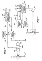
- the data communications system illustrated therein is adapted to provide data communications among a plurality of utilization devices UD I -UD S .
- the utilization devices UD,-UD 5 may comprise a plurality of avionic systems, or subsystems, or, a plurality of computer-related devices such as a central processing unit (CPU), input/output (I/O) devices, displays, memories, or the like.
- Each of the utilization devices UD,-UD 5 may include means for transmitting data, means for receiving data, or both.
- the data communications system includes a plurality of terminals TL I -TL, which are associated with respective ones of the utilization devices UD,-UD s , and also includes a common data communications medium to which the plurality of terminals TL,-TL 5 are coupled.
- the data communications medium comprises a data bus DB, which may take many forms, such as one or more electrical conductors, a magnetic member, a wave guide, or a fiber- optic member. It is not required, however, that the data communications medium be limited to a physical apparatus such as data bus DB, so that the data communications medium may comprise any appropriate carrier, such as audio, radio or light frequency waves or pulses, which is capable of carrying information by way of modulation thereof.
- each terminal includes a data communications link 10 for exchanging data with its associated utilization device, an output 12 upon which transmitted data appears and which is coupled to the data bus DB by a bus coupler 13, and an input 14 for receiving data present on the data bus DB, with the input 14 being coupled to the data bus DB by a bus coupler 15.
- the data bus DB includes a single twisted pair of wires extending to the physical locations of the utilization devices UD i ⁇ UDg
- bus couplers 13 and 15 each includes separable core elements that are adapted to be inserted into adjacent loops of the twisted pair of wires, all as described in EP-53638 published 16.06.82.
- the data to be transmitted and received using the data bus DB is in the form of messages comprising one or more, successive serial digital words.
- each terminal includes a demodulator 16 for demodulating the messages on the data bus DB which are received via coupler 15 and input 14 and for supplying the demodulated messages to a receiver 18.
- the demodulated messages are temporarily stored within the receiver 18, and the data therein is sent in an appropriate format to the associated utilization device under control of a terminal control unit 20 which exchanges "interface handshake" information with the utilization device and which provides the utilization device with an identification of the data that has been received.
- a transmitter 22 receives data from its associated utilization device, again under control of the terminal control unit 20, and outputs such data in the form of messages comprising one or more successive, serial digital words at times determined by the terminal control unit 20.
- a modulator 24 modulates the messages in a desired manner and supplies the modulated messages to the data bus DB via the output 12 and coupler 13.
- the terminal control units 20 in the plurality of terminals TL 1 - TLs utilize an identical and unique terminal control routine, or protocol, which ensures that only one terminal is transmitting at a given time.
- the data communications system as described is substantially identical to that described in U.S.P. 4,199,663.
- the specific protocol in that patent, hereinafter referred to as the A-mode protocol also ensures that, under steady-state conditions, transmissions by any terminal occur at periodic transmission intervals.
- the A-mode protocol requires that: (a) the transmission interval for each terminal be the nominal time interval between the initiation of periodic data transmissions by the terminal, and that the transmission intervals for all terminals be substantially the same in duration; (b) each transmitting terminal be capable of transmitting one message, including one or more data words, with appropriate synchronizing, label, parity and other information during each transmission interval; (c) each message can have any desired duration so long as such duration is fixed during times when periodic transmissions by the terminal are required and so long as the sum of the durations of the messages of all terminals, and all intermessage gaps, plus a growth gap required to accommodate additional terminals, does not exceed the duration of any transmission interval; (d) each transmitting terminal initiates a message transmission only upon occurrence of the expiration of an intermessage or "terminal" gap on the data bus which is unique to that transmitting terminal, and, the elapse of a period of time, from a previous message transmission by the terminal, which is substantially equal to the transmission interval; and (e) any inter
- the A-mode protocol is specifically designed for periodic message transmissions, use of this protocol in a data communications system of the type shown in Figure 1 limits the manner in which message transmissions may be made. For example, the rate of successive message transmissions by any terminal is limited by the duration of the transmission interval. If only a few of the terminals (e.g., terminals TL, and TL 2 ) are engaging in message transmissions, it will be seen that the data bus DB is silent for a substantial portion of time (e.g., that during which terminals TL 3 TL 5 would otherwise be engaging in message transmissions) so that the data bus is not utilized in an optimum manner.
- the requirement that the sum of the durations of the messages of all terminals, of all terminal gaps, and of the growth gap does not exceed the duration of any transmission interval limits the number of transmitting terminals that can be added to the data communication system unless the growth gap is made sufficiently long in duration, in which case the rate of successive message transmissions by any terminal is further limited.
- the requirement that successive messages by any terminal have a constant duration or length limits the amount of data that can be transmitted by any terminal at any point in time.
- each terminal control unit 20 may also implement a second, or B-mode, protocol which requires that: (a) each transmitting terminal initiates a message transmission only upon the successive occurrence of (i) an absence of messages on the data bus whose duration substantially equals that of a sync gap that is common to all terminals and (ii) an absence of messages on the data bus whose duration substantially equals that of a terminal gap unique to the terminal; (b) the duration of the sync gap must be longer than that of any terminal gap; and, (c) any interword gaps in any message have a duration which is less than that of the shortest terminal gap.
- B-mode second, or B-mode
- a gap detector 32 receives the demodulated messages from the receiver 18 and provides an output signal only when such demodulated messages are absent.
- a sync gap timer 34 is adpated to time the duration of each output signal from gap detector 32 and provides a momentary output signal only when the duration of any output signal from gap detector 32 is substantially equal to the sync gap common to all terminals. If an output signal from gap detector 32 terminates before expiration of the sync gap, timer 34 is internally reset. Any output signal from sync gap timer 34 sets a latch 36 which responsively provides an output signal to enable an AND gate 38 to pass any output signal from gap detector 32 to a terminal gap timer 40.
- terminal gap timer 40 when AND gate 38 is enabled, condition (i) of the B-mode protocol has been satisifed and terminal gap timer 40 thereafter times the duration of each output signal from gap detector 32.
- terminal gap timer 40 provides a momentary transmitter enable signal to the transmitter 22 so that transmitter 22 may transmit a message on the data bus DB. If an output signal from gap detector 32 terminates before expiration of the terminal gap, timer 40 is internally reset. The transmitter enable signal also resets latch 36, thereby disabling AND gate 38.
- terminal gap timer 40 is not thereafter supplied with any output signals from gap detector 32 until the absence of messages on the data bus again exceeds the sync gap and sync gap timer 34 again provides an output signal.
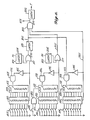
- Figure 3 comprises a timing chart illustrating a plurality of successive cycles of operation of the data communications system.
- Terminals TL 1 ⁇ TL 5 are each capable of transmitting messages, with each message including one or more data words, each data word being of a variable length and being preceded by a label identifying the data therein. In the case of a multiple data word message, the data words are separated by an interword gap.
- the cycles of operation illustrated in Figure 3 include successive cycles T 11 and T 12 .
- each of the terminals TL 1 -TL 5 transmits a message, that is, terminals TL 1 , TL 2 , TL 3 , TL 4 and TL 5 respectively transmit messages M 11 , M 21 , M 31 , M 41 , and M 51 .
- Messages M 11 , M 21 , M 41 and M 51 each include a single data word, with the data words being of variable length, and message M 31 includes two data words of equal length that are separated by an interword gap.
- cycle T 12 only terminals TL 1 , TL 2 and TL 5 transmit messages, these being messages M 12 , M 22 and M 52 , respectively.
- Each message in cycle T 12 includes a single data word, with the data words being of variable length.
- the durations of messages M 12 and M 22 are different from the corresponding durations of messages M 11 and M 21 .
- cycle T 11 is preceded by message M 50 from terminal TL 5
- cycle T 12 is succeeded by message M 13 from terminal TL 1 .
- the terminal control unit 20 in each of the terminals TL 1 ⁇ TL 5 establishes (through its terminal timer 40) a unique terminal gap for the associated terminal. That is, gaps tg 1 , tg 2 , tg 3 , tg 4 and tg 5 for terminals TL 1 , TL 2 , TL 3 , TL 4 and TL 5 , respectively (with tg 1 ⁇ tg 2 ⁇ tg 3 ⁇ tg 4 ⁇ tg 5 ).
- the terminal control unit 20 in each of the terminals TL 1 ⁇ TL 5 also establishes (through its sync gap timer 34) a sync gap that is common to all terminals.
- each sync gap timer 34 provides an output signal which sets its associated latch 36.
- each of the AND gates 38 is enabled so that each of the terminal gap timers 40 begins timing to initiate cycle T 11 .
- the terminal gap timer 40 in terminal TL 1 provides a transmitter enable.
- the terminal gap timers 40 in terminals TL 2 ⁇ TL 5 again begin timing.
- the terminal gap timer 40 in terminal TL 2 provides a transmitter enable signal which causes the transmitter in terminal TL 2 to initiate transmission of message M 21 and which resets the latch 36 in terminal TL 2 .
- the terminal gap timers in terminals TL 3 ⁇ TL 5 stop timing (and are reset) at the initiation of message M 21 , but the latches 36 therein remain set.
- terminals TL 3 , TL 4 and TL 5 successively transmit messages M 31 , M 41 and M 51 . Since the interword gap between the successive data words in message M 31 is chosen to be shorter than any terminal gap, it will also be seen that the terminal gap timers 40 in terminals TL 4 and TL 5 do not complete timing following the termination of transmission of the first data word in message M 3 , and the initiation of transmission of the second data word in message M 3 ,.
- each of the sync gap timers 34 provides an output signal which sets its associated latch 36.
- all of the AND gates 38 are now enabled and all of the terminal gap timers 40 begin timing to terminate ⁇ cycle T 11 and to initiate cycle T 12 .
- terminals TL, and TL 2 transmit messages M 12 and M 22 in a manner similar to that previously described after the successive expiration of terminal gaps tg, and tg 2 .
- the latches 36 in terminals TL 1 and TL 2 are reset and the latches 36 in terminals TL 3 ⁇ TL 5 remain set.
- the AND gates 38 in terminals TL 3 ⁇ TL 5 remain enabled and the terminal gap timers 40 therein each begin timing at the termination of message M 22 .
- the terminal gap timer 40 in terminal TL 3 provides a transmitter enable signal (which resets the latch 36 therein).
- no message transmission is actually made by terminal TL 3 in response to this transmitter enable signal.
- the AND gates 38 in terminals TL 4 and TL 5 remain enabled.
- the terminal gap timer 40 in terminal TL 4 After a time (from the termination of message M 22 ) equal to terminal gap tg 4 , the terminal gap timer 40 in terminal TL 4 provides a transmitter enable signal (which resets the latch 36 therein). However, no message is actually transmitted by terminal TL 4 in response to this transmitter enable signal. As a result, the AND gate 38 in terminal TL 5 remains enabled and the terminal gap timer 40 therein continues timing. After the expiration of a time (from the termination of message M 22 ) equal to terminal gap tg 5 , the terminal gap timer 40 in terminal TL 5 provides a transmitter enable signal (which resets the latch 36 therein). As a result, the transmitter in terminal TL S initiates transmission of message M 52 .
- each sync gap timer 34 Upon termination of message M S2 , all latches 36 have been reset and, after the expiration of a time equal to the sync gap, each sync gap timer 34 provides an output signal which sets its associated latch 36 so as to again enable each AND gate 38, whereby cycle T 12 terminates and a successive cycle is initiated (during which terminal TL, transmits message M 13 after expiration of terminal gap tg 1 , and so forth).
- the B-mode protocol can provide substantially periodic transmissions of successive messages from each terminal, provided that the same terminal or terminals are continuously engaged in message transmissions and that the successive messages from any terminal have substantially equal durations.
- the B-mode protocol will provide aperiodic message transmissions, as illustrated in Figure 3 in which the interval between messages M 11 and M 12 (e.g., that of cycle T 11 ), is greater than the interval between messages M 12 and M 13 (e.g., that of cycle T 12 ).
- the rate of message transmission by any terminal under the B-mode protocol will depend on the number of terminals that are transmitting messages and upon the length of these messages. As the number of transmitting terminals and/or the message lengths increase, the rate of transmission decreases.
- the data bus DB is utilized in an optimum manner, for it will be seen that the data bus is silent for a maximum time equal to the sum of the sync gap and the longest terminal gap (e.g., tg 5 ), assuming that at least one terminal is transmitting messages, and for a minimum time equal to the sum of the sync gap and the shortest terminal gap (e.g., tg i ).
- Successive messages from any terminal can be of any length, since the B-mode protocol only imposes conditions upon the absence of messages on the data bus.
- a data communications system operating under the B-mode protocol can accommodate any number of transmitting terminals without having to reset the transmission intervals or provide an extensive growth gap as with the A-mode protocol, subject to the limitation of a decreasing message transmission rate as previously described.
- the sync gap timers 34 and the terminal gap timers 40 in all of the terminals have a stable time base so that the sync gap does not become shorter than the terminal gap of any terminal and so that the terminal gap of any terminal does not approximate that of any other terminal.
- the time base establishing the interword gap in each of the terminals must be stable so that the interword gap of any terminal does not equal or exceed any terminal.
- each terminal includes a terminal monitor 40 ( Figure 2) which receives signals from the receiver 18, the terminal control unit 20, and the transmitter 22 therein.
- Each terminal monitor 40 includes an independent time base which establishes the desired interword gap, terminal gap, and sync gap for its associated terminal.
- the terminal monitor 40 also includes circuitry for comparing the actual interword gap, terminal gap and sync gap provided by the timers in its associated terminal control unit (such as sync gap timer 34 and terminal gap timer 40) with the desired interword gap, terminal gap and sync gap established by the independenttime base therein. If any of these comparisons fail to be made, the terminal monitor 40 supplies a signal to a modulator enable switch 42 which responsively removes power from the modulator 24 to inhibit further transmissions by the associated terminal.
- the data bus DB comprises a twisted pair of wires 100 extending to all terminals, with the terminations (not illustrated) of the twisted pair of wires 100 being short-circuited so that the data bus DB comprises a single, continuous current loop.
- Messages on data bus DB are in the form of currents, and are coupled to and from each transmitting terminal by an associated bus coupler 102 which includes a core 104, having separable core elements, whose legs are inserted into two adjacent loops formed by the twisted pair of wires 100 so that each wire thereof constitutes a single turn of a primary winding of the bus coupler 102.
- a secondary winding 106 is also wound around a core 104 and in interconnected with the transmitting terminal by a terminal stub 108 comprising a twisted pair of wires.
- the terminal stub 108 is connected in common to the input of a demodulator 110 and to the output of a modulator 112.
- the output from demodulator 110 comprises a signal DMR which represents the demodulated messages and which is applied to the input of a receiver 114 whose construction and operation will be described hereinafter with reference to Figure 6.
- the outputs from receiver 114 comprise a signal ADA, which is produced upon the absence of messages upon the data bus DB, and output signals DR, which represent the data within any valid message received by the receiver 114 that is addressed to the terminal (by the label previously described).
- Output signals DR may be in either parallel or serial digital form.
- An interface unit 116 is provided for controlling the interchange of data between the terminal and its associated utilization device 118. In response to interface receive control signals IRC from receiver 114, the received data represented in output signals DR is stored in interface unit 116. Within interface unit 116, the received data is converted to any desired form and thereafter transferred to utilization device 118.
- Utilization device 118 provides the data to be transmitted in an appropriate form to interface unit 116.
- the data to be transmitted is stored, converted to appropriate parallel or serial digital form, and transferred as output signals DT to a transmitter 120 in response to an interface transmit control signal ITC from transmitter 120.
- transmitter 120 provides an output signal DM, in serial digital form, that represents the data to be transmitted, the label or address of the terminal, and other data such as synchronizing and parity information.
- the signal DM and a signal T from transmitter 120 are applied to modulator 112 whose output has three distinct states.
- the output of modulator 112 has a high impedance so as to decouple the modulator 112 from the data bus DB.
- the output of modulator 112 has present thereon an output signal which alternates between first and second levels in response to the signal DM, with the first and second levels being respectively positive and negative.
- the output signal from modulator 112 is applied directly to the input of demodulator 110, and via terminal stub 108 and bus coupler 102 to the data bus DB.
- each message transmission may be Manchester bi-phase level modulation, wherein successive positive and negative levels in the output signal from modulator 112 represent a "1" and successive negative and positive levels in the output signal from the modulator 112 represent a ..0,..
- the demodulator 110 and receiver 114 include an amplifier 130 which provides a POS output for the duration of each positive level of the signal on data bus DB, and which provides an NEG output for the duration of each negative level of the signal on the data bus DB. At all other times, amplifier 140 provides no output.
- the POS and NEG outputs of amplifier 130 are applied to respective inputs of an OR gate 132 whose output comprises the signal ADA.
- the signal ADA is at a high logic level, signifying the presence of a message on the data bus DB.
- the signal ADA switches to a low logic level, signifying the absence of any messages on the data bus DB.
- the signal ADA is supplied to a protocol control unit 140 which also receives a transmit clock signal XXL from a transmit clock 142.
- Protocol control unit 140 determines if the protocol being used (which may be the A-mode protocol, the B-mode protocol or a combination thereof) has been satisfied, and, if so, supplies an output signal T to a data buffer, encoder and interface control circuit 144 and to a line driver 146 to initiate message transmission by the terminal.
- circuit 144 will have obtained any data to be transmitted from the associated utilization device 118 through interface unit 116 by supplying signal IRC to interface unit 116 and by receiving the data to be transmitted via output signals DT, and will have encoded the data into an appropriate message format along with synchronizing, label, parity and other information.
- the encoded message is provided to line driver 146 as signal DM which has successive first and second logic levels corresponding to the encoded information.
- the output from line driver 146 (which comprises the modulator 112 in Figure 5) is tri-stated or at a high impedance.
- line driver 146 converts each first logic level of the signal DM from data buffer, encoder and interface control circuit 144 into a corresponding positive level, and each second logic level of signal DM into a corresponding negative level, with the output from line driver 146 being coupled to data bus DB as previously described.
- circuit 144 supplies a signal SPX to protocol control unit 140 which responsively terminates signal T to accordingly return the output from line driver 146 to its tri-state level.
- data buffer, encoder and interface control circuit 144 may take many forms, a specific embodiment thereof useful in producing fixed-duration messages having a predetermined message format can be seen in Figure 7 of EP-20636.
- the signal ADA in the receiver 114 is applied to the input of a clock control circuit 150 which may comprise an R/S flip-flop.
- clock control circuit 150 When the signal ADA goes to a low logic level, signifying the absence of a message on the data bus, clock control circuit 150 is set to a first state in which an output signal R therefrom has a high logic level.
- the signal R is applied to a receiver clock 152 which is operative to provide a receiver clock signal RCL whenever the signal R has a high logic level.
- Both signal RCL and the POS output of amplifier 130 are applied to respective inputs of a data buffer, decoder, and interface control circuit 154 which responsively stores the information of the message that is represented by the successive levels of the signal on the POS output.
- Circuit 154 also decodes the message information stored therein, conducts certain tests on the synchronizing, label and parity information, and, if these tests have been satisfied, supplies the data in the message to interface unit 116 via output signals DR under control of signal IRC.
- a signal SPD is produced thereby which sets clock control 150 to its second state, whereby signal R goes to a low logic level to disable receiver clock 152 to accordingly terminate the transfer of any further information into circuit 154.
- data buffer, decoder and interface control circuit 154 may take many forms, a specific embodiment thereof useful for fixed-duration messages having a predetermined message format can be seen in Figure 6 of EP-20636.
- a specific embodiment of the protocol control unit 140 includes a sync gap timer, a transmission interval timer, and a terminal gap timer.
- the sync gap timer includes a comparator 160, a counter 162, a plurality of select switches 164, an inverting amplifier 166, and an AND gate 168;
- the transmission interval timer includes a comparator 170, a counter 172, a plurality of select switches 174, an inverting amplifier 176, an AND gate 178, an AND gate 180, and a switch 182;
- the terminal gap timer includes a comparator 190, a counter 192, a plurality of select switches 194, an inverting amplifier 196, and an AND gate 198.
- counter 162 is a multibit (e.g., eight bit) digital counter.
- the count within counter 162 is cleared and remains cleared whenever signal ADA (which is applied to a CLR input thereof) has a high logic level (signifying the presence of a message on the data bus), and is incremented by the output from AND gate 168 (which is applied to a clock or C input of counter 162).
- Comparator 160 is a multi-bit (e.g., eight bit) comparator that has a plurality of first inputs and a plurality of second inputs, the plurality of first inputs being connected to corresponding stages of counter 162 and the plurality of second inputs each being connected to one of the plurality of select switches 164.
- Comparator 160 functions to compare the count within counter 162 with a desired count, representing the duration of the sync gap, which is established by the setting of the plurality of select switches 164.
- the output signal from comparator 160 is applied through inverting amplifier 166 to a first input of AND gate 168 and to a set input of a latch 169 through an OR gate 167 (whose function will be described hereinafter), and the transmit clock signal XXL is applied to a second input of AND gate 168.
- the count within counter 162 at a time corresponding to the desired sync gap, will correspond to the desired count established by select switches 164, whereby the output signal from comparator 160 goes to a high logic level to disable AND gate 168 so that the output signal from comparator 160 is maintained at a high logic level.
- latch 169 is set and an output signal BIU therefrom goes to a high logic level, thereby signifying detection of the sync gap for the terminal. It will be noted that if a message appears on the data bus before expiration of the sync gap, the resultant high logic level in signal ADA clears counter 162 before the aforementioned comparison is made so that latch 169 is not set.
- counter 192 is a multibit (e.g., eight bit) digital counter whose count is cleared and remains cleared whenever signal ADA (which is applied to a CLR input thereof) has a high logic level, and whose count is incremented by the output from AND gate 198 (which is applied to a clock or C input of counter 192).
- Comparator 190 is a multibit (e.g., eight bit) comparator which compares the count within counter 192 with a desired count representing the terminal gap for the terminal that is established by the setting of the plurality of select switches 194. When the two counts do not correspond, an output signal TGU from comparator 190 has a low logic level and, when the two counts do correspond, output signal TGU has a high logic level.
- Output signal TGU is applied through inverting amplifier 196 to a first input of AND gate 198, signal BIU (from latch 169) is applied to a second input of AND gate 198, and the transmitter clock signal XXL is applied to a third input of AND gate 198.
- Counter 192 having previously been cleared by a high logic level in signal ADA, is thereby enabled to count but AND gate 198 remains disabled until the signal BIU goes to a high logic level, signifying detection of the sync gap as previously described. Therefore, if the sync gap has not yet been detected, counter 192 remains cleared even through signal ADA has gone to a low logic level. Since the count within counter 192 does not correspond to the desired count for the terminal gap established by select switches 194, signal TGU remains at a low logic level.
- Signal BIU, signal TGU and a signal AIU from the transmission interval timer are each supplied to respective inputs of an AND gate 200.
- signal AIU remains at a high logic level. Accordingly, 'when both the sync gap and the terminal gap for the terminal have been detected as represented by high logic levels in signals BIU and TGU, respectively, an output signal STX from AND gate 200 goes to a high logic level.
- the output signal STX is applied to the set input of a latch 202 and to the reset input of the latch 169.
- the resultant high logic level in signal STX sets latch 202 which responsively provides the output signal T to enable message transmission as previously described.
- the high logic level in signal STX also resets latch 169, whereby signal BIU goes to a low logic level to disable AND gate 198 in the terminal gap timer, and whereby signal STX returns to a low logic level. Accordingly, once a message transmission is enabled under the B-mode protocol (through signal T), another message transmission by the terminal cannot be enabled until successive detection of the sync gap and the terminal gap for that terminal.
- the transmission interval timer includes a multibit (e.g., eight bit) counter 172 whose count is cleared and remains cleared whenever the output from AND gate 180 has a high logic level (with the output from AND gate 180 being applied to a CLR input of counter 172) and whose count is incremented by the output from AND gate 178 (which is applied to a clock or C input of counter 172).
- the inputs to AND gate 180 are the signal STX and that provided by switch 182.
- Comparator 170 is a multibit (e.g., eight bit) comparator that compares the count within counter 172 with a desired count representing the desired transmission interval that is established by the setting of the plurality of select switches 174. When the two counts do not correspond, the output signal from comparator 170 has a low logic level which, through inverting amplifier 176, enables AND gate 178 and when the two counts do correspond, the output signal from comparator 170 has a high logic level.
- the output signal from comparator 170 is coupled through an OR gate 177 (whose function will be described hereinafter) to an input of AND gate 200 as signal AIU.
- the count within counter 172 is incremented irrespective of the absence or presence of messages on the data bus. After expiration of the transmission interval, the two counts correspond, whereby the output signal from comparator 170 and signal AIU both go to a high logic level, thereby disabling AND gate 178 to maintain signal AIU at a high logic level.
- signal AIU has a high logic level, and assuming that the signals BIU and TGU have a high logic level, it will be seen that signal STX from AND gate 200 goes to a high logic level, thereby setting latch 202 to enable message transmission by the terminal (through signal T) and also clearing counter 172 (through AND gate 180).
- protocol control unit 140 in Figure 8 can be used to implement only the A-mode protocol, only the B-mode protocol, or a combination of the A-mode and B-mode protocols.
- select switches 164 are all closed, whereby the desired count representing the sync gap is zero, switch 182 is opened, and select switches 174 and 194 are set to represent desired counts for the transmission interval (whose duration is substantially the same for all terminals) and for the terminal gap (whose duration is unique to the terminal). Since the desired count established by select switches 164 is now zero, it will be seen that the output signal from comparator 160 remains at all times at a high logic level so that latch 169 remains set at all times.
- signal BIU remains at a high logic level, so that enablement of the initiation of message transmission (through a high logic level in signal STX) is made only upon the occurrence of both expiration of the transmission interval from a previous transmission by the terminal (represented by a high logic level in signal AIU) and the expiration of the terminal gap (represented by a high logic level in signal TGU).
- either switch 182 may be closed or select switches 174 may be all closed, and select switches 164 and 194 are set to represent a desired sync gap (which is common to all terminals) and a desired terminal gap for the terminal (which is unique to the terminal). Since the desired count established by select switches 174 is now zero or since counter 172 cannot be cleared by signal STX (since AND gate 180 is disabled), signal AIU remains at a high logic level so that enablement of the initiation of message transmission is made only upon the occurrence of the expiration of the sync gap (represented by a high logic level in signal BIU) and the successive expiration of the terminal gap (represented by a high logic level in signal TGU).
- switch 182 is opened and select switches 164, 174 and 194 are set to represent, respectively, a desired sync gap, a desired transmission interval, and a desired terminal gap.
- the terminal gap assigned to each unit must be unique, and the durations of the sync gap and of the transmission interval must be common to all terminals.
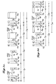
- the relative durations of the sync gap and of the transmission interval, along with the number of transmitting terminals and the message durations from such transmitting terminals, determine whether successive message transmissions from any terminal will be periodic (A-mode) or aperiodic (B-mode) as can be seen from the timing diagrams of Figures 9A and 9B.
- the data communications system includes terminals TL 1 ⁇ TL 5 (reference Figure 1), that the terminal gaps tg 1 -tg S associated with the terminals have a predetermined relationship (tg 1 ⁇ tg 2 ⁇ tg 3 ⁇ tg 4 ⁇ tg S ), that the sync gap is greater than the longest terminal gap, e.g., tg s , and that the transmission interval is longer in duration than the sync gap but shorter than the sum of all messages, terminal gaps, and the sync gap in a situation where all terminals are engaged in message transmissions.
- terminals TL 1 and TL 2 are the only “active" terminals engaging in message transmissions and that the remaining terminals TL 3 ⁇ TL 5 are "inactive" and deenergized.
- the latch 169 in terminal TL 1 is reset to disable the terminal gap timer therein and the transmission interval timer therein is also reset (by clearing the counter 172 as previously described) to initiate transmission interval T11.
- the latch 169 in terminal TL 2 is reset to disable the terminal gap timer therein and the transmission interval timer therein is also reset (by clearing the counter 172 as previously described) to initiate transmission interval T 2 ,.
- the sync gap timers in terminals TL 1 and TL 2 are reset.
- transmission interval T 11 has not yet expired, signal AIU in terminal TL 1 remains at a low logic level.
- the signal TGU in terminal TL 2 also goes to a high logic level.
- transmission interval T 2 has not yet expired, signal AIU in terminal TL 2 remains at a low logic level.
- transmission interval T 11 expires and the signal AIU in terminal TL, goes to a high logic level.
- each of the signals BIU, AIU and TGU in terminal TL 1 is at a high logic level, whereupon signal STX therein goes to a high logic level to set the latch 202 therein, to reset the latch 169 therein, and to reset the transmission interval timer therein to initiate transmission interval T, 2 .
- terminal TL 1 initiates transmission of message M 12 , whereby the sync gap timers and terminal gap timers in terminals TL, and TL 2 are reset.
- the terminal gap timer in terminal TL is disabled since signal BIU therein is at a low logic level (due to the resetting of the latch 169).
- the terminal gap timer in terminal TL 2 remains enabled.
- terminal TL 2 After an absence of messages on the data bus substantially equal to terminal gap tg 2 , the signal TGU in terminal TL 2 goes to a high logic level. At about this time, transmission interval T 2 , also expires, whereby signal AIU in terminal TL 2 also goes to a high logic level. At this time, each of the signals BIU, AIU and TGU in terminal TL is at a high logic level so that signal STX therein goes to a high logic level to set the latch 202 therein, to reset the latch 169 therein, and to reset the transmission interval timer therein to initiate transmission interval T 22 . In response to signal T, terminal TL 2 initiates transmission of message M 22 which resets the sync gap timers and terminal gap timers in terminals TL, and TL 2 .
- terminal TL 1 initiates transmission of message M 13 upon the expiration of terminal gap tg 1 and of transmission interval T 12 (whereby transmission interval T 13 is initiated), and terminal TL 2 initiates transmission of message M 23 upon expiration of terminal gap tg 2 and of transmission interval T 22 (whereupon transmission interval T 23 is initiated).
- terminal TL 3 is energized so that terminal TL 3 is ready to engage in message transmissions at the termination of message M 23 .
- the output signals from latches 204 and 206 are applied to second inputs of OR gates 167 and 177, respectively.
- Latches 204, 206 are set (whereby the output signals therefrom go to a high logic level) in response to a high logic level in a signal PU applied thereto, and are reset (whereby the output signals therefrom go to a low logic level) in response to a high logic level in signal STX.
- signal PU Whenever the terminal is energized, signal PU is caused to go to a high logic level for a short period of time (by means not illustrated), whereby latches 204 and 206 are set.
- the resultant high logic level in the output signal from latch 204 sets latch 169 (through OR gate 167) so that signal BIU goes to a high logic level, thereby signifying "detection” of the sync gap and also enabling the terminal gap timer in the terminal.
- the high logic level in the output signal from latch 206 causes signal AIU (through OR gate 177) to go to a high logic level, thereby signifying "detection" of the transmission interval for the terminal.
- the latches 169 in terminals TL 1 and TL 2 are reset and the latch 169 in terminal TL 3 is set, so that the terminal gap timers in terminals TL 1 and TL 2 are disabled and the terminal gap timer in terminal gap TL 3 is enabled.
- the transmission interval timers in terminals TL 1 and TL 2 are timing (since transmission intervals T 13 and T 23 have not yet expired), and expiration of the transmission interval for terminal TL 3 has been "detected", e.g., the signal AIU in terminal TL 3 is at a high logic level.
- terminal gap tg 3 Upon expiration of terminal gap tg 3 , the signal TGU in terminal TL 3 goes to a high logic level. At this time, each of the signals BIU, AIU and TGU in terminal TL 3 is at a high logic level, whereupon signal STX therein goes to a high logic level to set the latch 202 therein, to reset each of the latches 169, 204 and 206 therein, and to reset the transmission interval timer therein to initiate transmission interval T 33 . In response to signal T, terminal TL 3 initiates transmission of message M 33 , whereby the sync gap timers and terminal gap timers in terminals TL 1 , TL 2 and TL 3 are reset.
- each of the signals BIU, AIU and TGU in terminal TL 1 is at a high logic level, whereby terminal TL 1 initiates transmission of message M 14 and, in doing so, resets the latch 169 therein and resets the transmission interval timer therein to initiate a succeeding transmission interval.
- terminal gap tg 2 expires, whereupon terminal TL 2 initiates transmission of message M 24 and, in doing so, resets the latch 169 therein and resets the transmission interval timer therein to initiate a succeeding transmission interval.
- transmission interval T 33 expires.
- the signals BIU and AIU in terminal TL 3 are therefore at a high logic level, the signal TGU therein is not since terminal gap tg 3 has not yet expired so that terminal TL 3 is not able to transmit a message at this time.
- each of the signals BIU, AIU and TGU in terminal TL 3 is at a high logic level, whereupon terminal TL 3 initiates transmission of message M 34 and, in doing so, resets the latch 169 therein and resets the transmission interval timer therein to initiate a successive transmission interval. Thereafter, the operation of the system proceeds in a similar manner.
- the latches 169 in the terminals are set, thereby enabling each of the terminal gap timers.
- the signal TGU in terminal TL 1 goes to a high logic level.
- signal AIU in terminal TL 1 remains at a low logic level.
- the terminal gap TGU in terminal TL 2 also goes to a high logic level.
- the transmission interval T 23 has not yet expired, signal AIU in terminal TL 2 remains at a low logic level.
- terminal gap tg 3 Upon the expiration of terminal gap tg 3 (following expiration of the sync gap) the signal TGU in terminal TL 3 goes to a high logic level.
- each of the signals BIU, AIU and TGU in terminal TL 3 is at a high logic level, whereupon terminal TL 3 initiates transmission of message M 34 and, in doing so, resets the latch 169 therein to accordingly disable the terminal gap timer therein, resets the latch 206 therein, and resets the transmission interval timer therein to initiate transmission interval T 34 .
- each of the signals BIU, AIU and TGU in terminal TL 2 is at a high logic level, whereupon terminal TL 2 initiates transmission of message M 24 and, in doing so, resets the latch 169 therein and resets the transmission interval timer therein to initiate transmission interval T 24 .
- the signal TGU in terminal TL 2 Upon the expiration of terminal gap tg 2 (following expiration of the sync gap), the signal TGU in terminal TL 2 also goes to a high logic level. However, because transmission interval T 24 has not yet expired, signal AIU in terminal TL 2 remains at a low logic level.
- the signal TGU in terminal TL 3 goes to a high logic level. At this time, each of the signals BIU, AIU and TGU in terminal TL 3 is at a high logic level, whereupon terminal TL 3 initiates transmission of message M 35 and, in doing so, resets the latch 169 therein and resets the transmission interval timer therein to initiate a successive transmission interval.
- Transmission intervals T, 4 and T 24 expire during message M 35 , so that terminal TL 1 initiates transmission of message M 15 upon expiration of terminal gap tg 1 following termination of message M 35 , and terminal TL 2 initiates transmission of message M 25 upon expiration of terminal gap tg 2 following termination of message M 1s .
- the initial message transmissions by terminals TL 1 and TL 2 are periodic, that is, the interval between messages M 11 and M 12 , the interval between messages M 12 and M 13 , the interval between messages M 2 , and M 22 and the interval between messages M 22 and M 23 are each substantially equal in duration. Therefore, the initial portion of the timing diagram in Figure 9 illustrates a use of the data communication system in which message transmissions are under control of the A-mode protocol.
Landscapes
- Engineering & Computer Science (AREA)
- Computer Networks & Wireless Communication (AREA)
- Signal Processing (AREA)
- Power Engineering (AREA)
- Small-Scale Networks (AREA)
Claims (25)
Applications Claiming Priority (1)
| Application Number | Priority Date | Filing Date | Title |
|---|---|---|---|
| PCT/US1981/000182 WO1982002809A1 (fr) | 1981-02-11 | 1981-02-11 | Systeme ameliore de communications de donnees avec terminaux autonomes |
Publications (3)
| Publication Number | Publication Date |
|---|---|
| EP0070828A1 EP0070828A1 (fr) | 1983-02-09 |
| EP0070828A4 EP0070828A4 (fr) | 1983-06-17 |
| EP0070828B1 true EP0070828B1 (fr) | 1985-05-22 |
Family
ID=22161092
Family Applications (1)
| Application Number | Title | Priority Date | Filing Date |
|---|---|---|---|
| EP81901730A Expired EP0070828B1 (fr) | 1981-02-11 | 1981-02-11 | Systeme ameliore de communications de donnees avec terminaux autonomes |
Country Status (3)
| Country | Link |
|---|---|
| EP (1) | EP0070828B1 (fr) |
| DE (1) | DE3170568D1 (fr) |
| WO (1) | WO1982002809A1 (fr) |
Families Citing this family (2)
| Publication number | Priority date | Publication date | Assignee | Title |
|---|---|---|---|---|
| FR2558667B1 (fr) * | 1984-01-19 | 1987-03-20 | Minisystemes | Procede de transmission de donnees numeriques, reseau et module mettant en oeuvre le procede |
| GB2254982B (en) * | 1991-04-19 | 1995-06-14 | British Aerospace | Data networks |
Citations (1)
| Publication number | Priority date | Publication date | Assignee | Title |
|---|---|---|---|---|
| EP0020636A1 (fr) * | 1978-11-06 | 1981-01-07 | Boeing Co | Systeme de communication de donnees avec terminaux autonomes. |
Family Cites Families (3)
| Publication number | Priority date | Publication date | Assignee | Title |
|---|---|---|---|---|
| US4052566A (en) * | 1975-12-24 | 1977-10-04 | D.D.I. Communications, Inc. | Multiplexer transmitter terminator |
| GB2006491B (en) * | 1977-07-02 | 1982-01-06 | Ml Eng Plymouth | Data transmission system |
| US4156112A (en) * | 1977-12-07 | 1979-05-22 | Control Junctions, Inc. | Control system using time division multiplexing |
-
1981
- 1981-02-11 DE DE8181901730T patent/DE3170568D1/de not_active Expired
- 1981-02-11 EP EP81901730A patent/EP0070828B1/fr not_active Expired
- 1981-02-11 WO PCT/US1981/000182 patent/WO1982002809A1/fr not_active Ceased
Patent Citations (1)
| Publication number | Priority date | Publication date | Assignee | Title |
|---|---|---|---|---|
| EP0020636A1 (fr) * | 1978-11-06 | 1981-01-07 | Boeing Co | Systeme de communication de donnees avec terminaux autonomes. |
Also Published As
| Publication number | Publication date |
|---|---|
| WO1982002809A1 (fr) | 1982-08-19 |
| EP0070828A4 (fr) | 1983-06-17 |
| DE3170568D1 (en) | 1985-06-27 |
| EP0070828A1 (fr) | 1983-02-09 |
Similar Documents
| Publication | Publication Date | Title |
|---|---|---|
| US4471481A (en) | Autonomous terminal data communications system | |
| US4199663A (en) | Autonomous terminal data communications system | |
| US5359594A (en) | Power-saving full duplex nodal communications systems | |
| US8762760B2 (en) | Method and apparatus for adaptive power control in a multi-lane communication channel | |
| EP0622711B1 (fr) | Méthode et appareil pour la transmission de données dans un réseau de communications | |
| US4561092A (en) | Method and apparatus for data communications over local area and small area networks | |
| EP0070828B1 (fr) | Systeme ameliore de communications de donnees avec terminaux autonomes | |
| US5729547A (en) | Automatic driver/receiver control for half-duplex serial networks | |
| JPS6276948A (ja) | ロ−カルネツトワ−ク内の自動レベル等化方法 | |
| US20230403735A1 (en) | Message Transmission Method, Terminal and Storage Medium | |
| US4843605A (en) | Node apparatus for communication network having multi-conjunction architecture | |
| JPH06216969A (ja) | 直列メッセージ伝送方法および受信器 | |
| JPH033977B2 (fr) | ||
| JPH0377701B2 (fr) | ||
| EP0216379B1 (fr) | Procédé de communication et équipement y relatif | |
| US20050074057A1 (en) | System and method for modulation on demand in a computing device | |
| US5003582A (en) | Method of adjusting the end of transmission in a modem | |
| JPS62183646A (ja) | 自動終端回路 | |
| JPH066279A (ja) | 特定小電力無線装置のデータ伝送方式 | |
| JPH02312336A (ja) | 通信システム | |
| JPH0753145A (ja) | バスジャミング装置およびバスジャミング方法 | |
| JPS6248831A (ja) | 通信制御装置 | |
| JPS6292545A (ja) | デ−タ伝送装置 | |
| JP2558119B2 (ja) | 送受信回路 | |
| JPS63267036A (ja) | 衝突検出機能付送受信装置 |
Legal Events
| Date | Code | Title | Description |
|---|---|---|---|
| PUAI | Public reference made under article 153(3) epc to a published international application that has entered the european phase |
Free format text: ORIGINAL CODE: 0009012 |
|
| 17P | Request for examination filed |
Effective date: 19820913 |
|
| AK | Designated contracting states |
Kind code of ref document: A1 Designated state(s): DE FR GB NL SE |
|
| GRAA | (expected) grant |
Free format text: ORIGINAL CODE: 0009210 |
|
| AK | Designated contracting states |
Kind code of ref document: B1 Designated state(s): DE FR GB NL SE Designated state(s): DE FR GB NL SE |
|
| PG25 | Lapsed in a contracting state [announced via postgrant information from national office to epo] |
Ref country code: SE Effective date: 19850530 |
|
| REF | Corresponds to: |
Ref document number: 3170568 Country of ref document: DE Date of ref document: 19850627 |
|
| ET | Fr: translation filed | ||
| PLBE | No opposition filed within time limit |
Free format text: ORIGINAL CODE: 0009261 |
|
| STAA | Information on the status of an ep patent application or granted ep patent |
Free format text: STATUS: NO OPPOSITION FILED WITHIN TIME LIMIT |
|
| 26N | No opposition filed | ||
| PGFP | Annual fee paid to national office [announced via postgrant information from national office to epo] |
Ref country code: FR Payment date: 19990119 Year of fee payment: 19 |
|
| PGFP | Annual fee paid to national office [announced via postgrant information from national office to epo] |
Ref country code: GB Payment date: 19990121 Year of fee payment: 19 |
|
| PGFP | Annual fee paid to national office [announced via postgrant information from national office to epo] |
Ref country code: DE Payment date: 19990122 Year of fee payment: 19 |
|
| PGFP | Annual fee paid to national office [announced via postgrant information from national office to epo] |
Ref country code: NL Payment date: 19990126 Year of fee payment: 19 |
|
| PG25 | Lapsed in a contracting state [announced via postgrant information from national office to epo] |
Ref country code: GB Free format text: LAPSE BECAUSE OF NON-PAYMENT OF DUE FEES Effective date: 20000211 |
|
| PG25 | Lapsed in a contracting state [announced via postgrant information from national office to epo] |
Ref country code: NL Free format text: LAPSE BECAUSE OF NON-PAYMENT OF DUE FEES Effective date: 20000901 |
|
| GBPC | Gb: european patent ceased through non-payment of renewal fee |
Effective date: 20000211 |
|
| PG25 | Lapsed in a contracting state [announced via postgrant information from national office to epo] |
Ref country code: FR Free format text: LAPSE BECAUSE OF NON-PAYMENT OF DUE FEES Effective date: 20001031 |
|
| NLV4 | Nl: lapsed or anulled due to non-payment of the annual fee |
Effective date: 20000901 |
|
| PG25 | Lapsed in a contracting state [announced via postgrant information from national office to epo] |
Ref country code: DE Free format text: LAPSE BECAUSE OF NON-PAYMENT OF DUE FEES Effective date: 20001201 |
|
| REG | Reference to a national code |
Ref country code: FR Ref legal event code: ST |