EP0070947A1 - Hydraulikdichtung für zweiseitige Abdichtung - Google Patents
Hydraulikdichtung für zweiseitige Abdichtung Download PDFInfo
- Publication number
- EP0070947A1 EP0070947A1 EP81420118A EP81420118A EP0070947A1 EP 0070947 A1 EP0070947 A1 EP 0070947A1 EP 81420118 A EP81420118 A EP 81420118A EP 81420118 A EP81420118 A EP 81420118A EP 0070947 A1 EP0070947 A1 EP 0070947A1
- Authority
- EP
- European Patent Office
- Prior art keywords
- ring
- sealing
- lips
- seal according
- piston
- Prior art date
- Legal status (The legal status is an assumption and is not a legal conclusion. Google has not performed a legal analysis and makes no representation as to the accuracy of the status listed.)
- Granted
Links
- 238000007789 sealing Methods 0.000 claims abstract description 66
- 239000000463 material Substances 0.000 claims abstract description 13
- 230000006870 function Effects 0.000 claims description 14
- 238000007790 scraping Methods 0.000 claims description 12
- 239000011324 bead Substances 0.000 claims description 6
- 238000012856 packing Methods 0.000 claims description 5
- 208000000044 Amnesia Diseases 0.000 claims description 3
- 231100000863 loss of memory Toxicity 0.000 claims description 2
- 238000006243 chemical reaction Methods 0.000 description 3
- 240000000018 Gnetum gnemon Species 0.000 description 2
- 235000008612 Gnetum gnemon Nutrition 0.000 description 2
- 240000008042 Zea mays Species 0.000 description 2
- 230000007423 decrease Effects 0.000 description 2
- 239000012530 fluid Substances 0.000 description 2
- 239000012535 impurity Substances 0.000 description 2
- 238000004519 manufacturing process Methods 0.000 description 2
- 208000026139 Memory disease Diseases 0.000 description 1
- 238000009825 accumulation Methods 0.000 description 1
- 230000000712 assembly Effects 0.000 description 1
- 238000000429 assembly Methods 0.000 description 1
- 230000005540 biological transmission Effects 0.000 description 1
- 239000002131 composite material Substances 0.000 description 1
- 230000006835 compression Effects 0.000 description 1
- 238000007906 compression Methods 0.000 description 1
- 230000003247 decreasing effect Effects 0.000 description 1
- 230000000694 effects Effects 0.000 description 1
- 230000008030 elimination Effects 0.000 description 1
- 238000003379 elimination reaction Methods 0.000 description 1
- 238000001125 extrusion Methods 0.000 description 1
- 238000009434 installation Methods 0.000 description 1
- 230000006984 memory degeneration Effects 0.000 description 1
- 208000023060 memory loss Diseases 0.000 description 1
- 238000007747 plating Methods 0.000 description 1
- 230000001737 promoting effect Effects 0.000 description 1
- 230000000717 retained effect Effects 0.000 description 1
Images


Classifications
-
- F—MECHANICAL ENGINEERING; LIGHTING; HEATING; WEAPONS; BLASTING
- F16—ENGINEERING ELEMENTS AND UNITS; GENERAL MEASURES FOR PRODUCING AND MAINTAINING EFFECTIVE FUNCTIONING OF MACHINES OR INSTALLATIONS; THERMAL INSULATION IN GENERAL
- F16J—PISTONS; CYLINDERS; SEALINGS
- F16J15/00—Sealings
- F16J15/56—Other sealings for reciprocating rods
-
- F—MECHANICAL ENGINEERING; LIGHTING; HEATING; WEAPONS; BLASTING
- F16—ENGINEERING ELEMENTS AND UNITS; GENERAL MEASURES FOR PRODUCING AND MAINTAINING EFFECTIVE FUNCTIONING OF MACHINES OR INSTALLATIONS; THERMAL INSULATION IN GENERAL
- F16J—PISTONS; CYLINDERS; SEALINGS
- F16J15/00—Sealings
- F16J15/16—Sealings between relatively-moving surfaces
- F16J15/32—Sealings between relatively-moving surfaces with elastic sealings, e.g. O-rings
Definitions
- the present invention relates to a double-acting hydraulic seal, in particular ensuring dynamic sealing between the inner wall of a cylinder and a piston sliding in said cylinder and separating two chambers at different or non-pressure, the piston possibly being free or coupled to a power transmission rod.
- the invention makes it possible to ensure, with great reliability, this type of sealing, even when the piston is driven by a rotary movement of medium speed, combined or not with its rectilinear reciprocating movement.
- an object of the invention is to provide an assembly allowing the use of one-piece or two-part pistons comprising a simple groove, more or less long, easy.
- the invention aims to provide, in particular for hydraulic cylinders, an assembly capable of performing multiple functions, namely: sealing, guiding and scraping, these three functions being fulfilled, in the simplest case, by a single and same main part, the assembly being composed in this case of only two elements.
- the subject of the invention is essentially a double-acting hydraulic seal, such as the assembly of a ring of rigid material and a flexible thrust ring housed in an inner annular groove of said ring. , the assembly being mounted in a groove of the piston bounded by two shoulders, and the ring comprising, between .two main parts-with guiding function, two sealing lips situated in line with the thrust ring and subjected to the 'action of the latter, while the two ends of the ring form wings of thickness less than that of the two main parts, each wing itself being extended by a scraper lip.
- the gasket thus produced ensures, by the same main element which is the ring, the three functions of sealing (by the central part), of guiding and scraping (by the ends) and it constitutes an assembly which can be mounted by radial extension. in a single long groove of a piston with a simple structure.
- each of the two sealing wings is advantageously connected to the adjacent main part of the ring by means of a thin hinge zone; the sealing lips have a thicker section in line with their respective contact edges.
- each sealing lip thickens as one moves away from its base of attachment to the adjacent main part of the ring.
- the thin hinge area is necessary, taking into account that the sealing and guiding elements are made in the same hard material and you have to give the lip some flexibility.
- the sealing contact being made of hard material, does not undergo the so-called gumming effects generally observed when the seals are made with flexible materials of low hardness.
- another distinction with respect to current embodiments is the fact that the attachment base of each sealing lip, instead of being relatively reduced, is very long and has the role of guiding the 'and not the resistance to extrusion of the sealing lip.
- the ring is a non-block piece, in which case the two sealing lips are connected together by a very hinged zone fine, delimiting a small external groove, which retains a small ring of oil favoring the sliding, by further improving the already excellent coefficient of friction of this kind of lining.
- the hinge zones connecting the sealing lips to the main parts of the ring and / or connecting them together, are capable of restoring, as a result of the deformation of the sealing lips, forces compensating for the "loss of memory "of the material of the thrust ring.
- This additional characteristic constitutes an advantageous novelty compared to the so-called composite seals which are commercially available, generally constituted by a contact ring maintained applied to the surface to be sealed by an internal pressure ring.
- the invention makes it possible to obtain plating forces of three different types which add up, and which have their sources at four different points: the thrust ring, the two hinge zones connecting the sealing lips to the adjacent main parts of the ring, and the hinge zone connecting the two sealing lips together.
- the thrust ring the two hinge zones connecting the sealing lips to the adjacent main parts of the ring
- the hinge zone connecting the two sealing lips together This gives an improved sealing quality and above all made constant over time, all the more so as the sealing contact takes place along lines and not surfaces, at least when the packing is new.
- the contact lines will gradually thicken but will always remain very weak.
- the ring is split into two parts, symmetrical or not, each of which comprises: a main body with guiding function, a sealing lip connected to the body main, in particular by a hinge zone, but not connected to the sealing lip of the other part, and opposite to the sealing lip, a wing extended by a scraper lip.
- this other embodiment simply results from the elimination of the central hinge previously connecting together the two sealing lips; the profiles and the functions of the various parts of the ring, in particular for the sealing and scraping lips , are not modified, and the assembly is always mounted in a single groove of a piston.
- the pushing ring is housed inside two "half-grooves" formed in the extreme regions, located opposite, of the two parts of the ring.
- This pushing ring may include, in its middle, an external annular bead of wiping, engaged in the gap which remains between the two sealing lips not connected to each other, in which case the small oil retaining groove, previously mentioned, no longer exists.
- the seal object of the invention comprises a one-piece ring 1 made of rigid material, in the center of which is formed, internally, an annular groove 2 constituting the housing of a flexible ring thrust 3.
- This ring 3 has the role of maintaining a constant pressure on two symmetrical sealing lips 4, formed in the central part of the ring 1 in line with the groove 2 and belonging to said ring 1.
- wings 5 of thickness thinner than that of the two main parts 6 of the ring 1 with guiding function.
- the assembly constituted by the ring 1 and by the thrust ring 3 can thus be mounted in a long groove 7 of a piston 8, and retained axially by the two annular shoulders 9 which delimit this groove 7, said shoulders 9 corresponding to the internal recesses 10 separating the thick parts 6 and the wings 5.
- Each wing 5 of reduced thickness is itself extended by a scraping lip 11.
- FIG. 2 therefore shows the central region of the ring 1, the main part of the lining, with its annular groove 2, the depth of which is indicated at 12 and the length at 13, which receives the thrust ring 3, the cross section of which has a height equal to the depth 12 of the groove 2, and whose length 14 is slightly less than that 13 of the groove 2.
- the groove 2 can obviously be produced in another intermediate location than the middle of the ring 1, for example to satisfactorily adapt the lining to a piston 8 produced in two symmetrical parts; in this case, the groove 2 will be provided in the off-center position, in order to prevent the junction line of the two symmetrical parts of the piston from being under the thrust ring 3.
- the two sealing lips 4, located at the right of the groove 2 in all cases, are produced according to the non-limiting profile shown by way of example in FIG. 2. These lips 4 have a significant thickness at the right of their sealing contact edges 15, but are connected via a hinge zone 16 relatively thin to the adjacent main parts 6 of the ring 1. In addition, the two lips 4 are connected to each other by another very hinge zone fine 17.
- the internal profile 20 of the sealing lips 4 will slide slightly on the external surface of the thrust ring 3.
- the internal profile 20 of each lip 4 is curved along a certain radius 21, near the hinge zone 17 connecting the two lips 4 together. As shown in Figure 3, the ring 3 will be crushed without damage by the curved parts of the profile 20, which deform its outer surface and generate in said ring 3 reaction forces 22, decreasing values as and one moves away from the sealing contact edges 15.
- the thin hinge zones 16 register and memorize tensions, which generate forces tending to bring out, along arrow 23, the sealing lips 4, these forces adding to those 22 exerted by the thrust ring 3 to ensure the sealing contact of the edges 15-
- the very fine hinge zone 17, connecting the two sealing lips 4 together, also stores tensions which further complete the reactions caused by the hinge zones 16 and by the thrust ring 3.
- the double contact edge 15 can be replaced by a single central edge 24 common to the two lips 4 (dotted on Figure 2).
- the rectilinear external profile 25 of the sealing lips 4 can also be replaced by a concave profile, such as for example that 26 (in dotted lines in FIG. 2), in order to maintain over time a perfectly linear contact by the edge 15 .
- the small outer central groove 27 located between the two edges 15, in the case of a lining with double contact line, makes it possible to keep, in the center of the sealing part, a small ring of oil promoting sliding.
- the reduced annular section 28 of the wing 5 is determined so that the residual section 29 is sufficient, so that the forces transmitted by the annular face limiting the main part 6, at the level of the step 10, do not cause, on the shoulder 9 of the piston 8, reactions per unit area resulting in compression ratios greater than the mechanical characteristics of the material of which the ring 1 is made.
- the wing 5 is supported on a cylindrical surface 30 of the piston 8, and it is extended, as already indicated above, by a scraping lip 11.
- This lip 11 is elongated and extends, in an oblique direction, towards the outside. It is connected to the wing 5 by a thick hinge zone 31, but markedly thinner than the annular section 28 of the wing 11. The lip 11 becomes thinner towards its free end, and it ends in an edge long live 32.
- the impurities which could be on the internal wall 18 of the cylinder are scraped by the lip 11 and brought, according to arrow 33, towards the frustoconical end face 34 of the piston 8, without risk of accumulation of these impurities at the level of the edge 32 in contact with the wall of the cylinder.
- the lip 11 ensures effective scraping as has just been described, but it does not achieve total sealing.
- the hydraulic fluid can pass over the edge 32, even that it can infiltrate along the cylindrical surface 30 of the piston 8 and along the bottom of the groove? of the piston 8. This fluid can thus supply the central groove 2 of the ring 1, and subject the thrust ring 3 to a slight deformation, capable of compensating for the "memory loss" of this ring 3.
- the whole of the packing is mounted on the piston 4 by a slight extension in the radial direction, the mounting operation being facilitated by the frustoconical face 34 of the piston 8.
- the use of a press may be necessary, to increase the internal diameter of the ring 1 until the diameter of the cylindrical surface 30 of the piston 8 is reached.
- this mounting operation the thrust ring 3 remains in place in the groove 2 of the ring 1, and in the same way it undergoes an extension when passing over the cylindrical surface 30 of the piston 8.
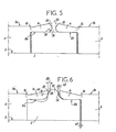
- the hinge zone connecting the two sealing lips 4 to one another is eliminated, so that the ring is split into two parts 1a and 1b.
- the sealing lips 4 retain the same shapes and characteristics as those described above; they can be in particular with a negative cut giving the edges 15, or with a positive cut giving the edges 35 (in dotted lines).
- the gap 36 which remains here between the two lips 4 appreciably increases the central oil ring remaining between the two edges 15.
- the sealing lips 4 always cooperate as described above with the thrust ring 3, mounted in two "half-grooves" 2a and 2b, and the other parts of the lining, which provide the guiding and scraping functions, are produced and operate in a manner identical to the detailed description given above in the case of a monobloc ring.
- the scraping ends of the two parts 1a and 1b can be identical to that shown in FIG. 4.
- FIG. 5 can be adopted when the quantities of linings to be produced to meet the market are insufficient to justify the creation of molds with retractable core, making it possible to - produce the inner central groove 2 of FIGS. 1 to 3.
- the realization of the ring in two parts 1a and 1b however remains more expensive because it requires two separate manufacturing operations.
- the lining object of the invention and split into two parts la and 1b can be executed according to a variant illustrated by FIG. 6:
- the two sealing lips 4 are always separated from each other by a gap 36, but the thrust ring 3 here comprises, in its middle, an external annular wiping bead 37 engaged in the gap 36 .
- the lateral lateral generatrices 38 of the bead 37 are inclined at an angle 39 equal to the pivoting angle 40 described by the sealing lips 4, around their respective hinge zones 16, when they are put in place.
- the axial clearance 41 of the ring 3 in the groove 2a, 2b is equal to the clearance 42 of the bead 37 between the two lips 4; this way along with the side faces of the ring 3 are pressed against the facing surface belonging to part 1a or 1b of the ring, the bead 37 is pressed along the nose of one of the sealing lips 4.
- FIG. 6 is particularly applicable when, in the case of an embodiment of the ring in two parts 1a and 1b, it is desired to remove the central oil ring, as is achieved in the version, " monobloc "by providing a single central sealing edge 24 (FIG. 2).
Landscapes
- Engineering & Computer Science (AREA)
- General Engineering & Computer Science (AREA)
- Mechanical Engineering (AREA)
- Sealing Devices (AREA)
- Glass Compositions (AREA)
- Pistons, Piston Rings, And Cylinders (AREA)
- Actuator (AREA)
Priority Applications (3)
| Application Number | Priority Date | Filing Date | Title |
|---|---|---|---|
| DE8181420118T DE3167079D1 (en) | 1981-07-30 | 1981-07-30 | Double acting hydraulic seal |
| EP81420118A EP0070947B1 (de) | 1981-07-30 | 1981-07-30 | Hydraulikdichtung für zweiseitige Abdichtung |
| AT81420118T ATE10227T1 (de) | 1981-07-30 | 1981-07-30 | Hydraulikdichtung fuer zweiseitige abdichtung. |
Applications Claiming Priority (1)
| Application Number | Priority Date | Filing Date | Title |
|---|---|---|---|
| EP81420118A EP0070947B1 (de) | 1981-07-30 | 1981-07-30 | Hydraulikdichtung für zweiseitige Abdichtung |
Publications (2)
| Publication Number | Publication Date |
|---|---|
| EP0070947A1 true EP0070947A1 (de) | 1983-02-09 |
| EP0070947B1 EP0070947B1 (de) | 1984-11-07 |
Family
ID=8188581
Family Applications (1)
| Application Number | Title | Priority Date | Filing Date |
|---|---|---|---|
| EP81420118A Expired EP0070947B1 (de) | 1981-07-30 | 1981-07-30 | Hydraulikdichtung für zweiseitige Abdichtung |
Country Status (3)
| Country | Link |
|---|---|
| EP (1) | EP0070947B1 (de) |
| AT (1) | ATE10227T1 (de) |
| DE (1) | DE3167079D1 (de) |
Families Citing this family (1)
| Publication number | Priority date | Publication date | Assignee | Title |
|---|---|---|---|---|
| CN114483962B (zh) * | 2022-04-02 | 2022-06-24 | 东营海森密封技术有限责任公司 | 一种机翼形动压非接触式密封结构 |
Citations (1)
| Publication number | Priority date | Publication date | Assignee | Title |
|---|---|---|---|---|
| FR2231267A5 (de) * | 1973-05-21 | 1974-12-20 | Dechavanne Jacques |
-
1981
- 1981-07-30 EP EP81420118A patent/EP0070947B1/de not_active Expired
- 1981-07-30 AT AT81420118T patent/ATE10227T1/de not_active IP Right Cessation
- 1981-07-30 DE DE8181420118T patent/DE3167079D1/de not_active Expired
Patent Citations (1)
| Publication number | Priority date | Publication date | Assignee | Title |
|---|---|---|---|---|
| FR2231267A5 (de) * | 1973-05-21 | 1974-12-20 | Dechavanne Jacques |
Also Published As
| Publication number | Publication date |
|---|---|
| EP0070947B1 (de) | 1984-11-07 |
| DE3167079D1 (en) | 1984-12-13 |
| ATE10227T1 (de) | 1984-11-15 |
Similar Documents
| Publication | Publication Date | Title |
|---|---|---|
| EP0024986B1 (de) | Verfahren zum Ausrüsten einer Leitung mit einer Verbindungsmuffe und Verwendung dieser Verbindungsmuffen für die Verbindung von Leitungen | |
| EP0034549B1 (de) | Verfahren zum Einrollen von Rohren in Platten und Werkzeug zur Durchführung dieses Verfahrens | |
| EP3167148B1 (de) | Aufweitbares röhrenförmiges element zur aufnahme von einer oder mehreren aufblasbaren dichtungen | |
| FR3032765A1 (fr) | Dispositif d'etancheite pour paliers a roulement, en particulier pour un palier de moyeu de vehicules, et roulement de moyeu associe. | |
| FR2635162A1 (fr) | Bloc filtre de protection, dispositif d'etancheite aux fluides et mecanisme hydraulique etanche | |
| FR2576383A1 (fr) | Joint d'etancheite a monter sur le troncon conique d'un tourillon de cylindre de laminoir | |
| FR2617923A1 (fr) | Palier spherique et son procede de fabrication | |
| FR2796686A1 (fr) | Soufflet et joint de transmission correspondant | |
| FR3010130A1 (fr) | Element tubulaire avec etancheite dynamique et son procede d'application contre la paroi d'un puits | |
| FR2630179A1 (fr) | Joint d'etancheite en cartouche | |
| FR2467335A1 (fr) | Joint annulaire d'etancheite a l'huile | |
| FR2492034A1 (fr) | Garniture radiale d'etancheite | |
| EP2932139B1 (de) | Dichtung für eine elektrische verbindung | |
| EP0070947B1 (de) | Hydraulikdichtung für zweiseitige Abdichtung | |
| FR2598769A1 (fr) | Garniture d'etancheite hydraulique ou pneumatique | |
| FR2712655A1 (fr) | Joint d'étanchéité. | |
| FR2486617A1 (fr) | Garniture d'etancheite hydraulique a double effet | |
| EP1547728B1 (de) | Backe für Pressverbindung | |
| FR2482878A1 (de) | ||
| FR2594519A1 (fr) | Garniture mecanique d'etancheite pour arbre tournant et son procede de fabrication | |
| FR2496820A1 (fr) | Agencement de joint entre deux pieces se deplacant axialement l'une relativement a l'autre dans des appareils hydrauliques ou pneumatiques | |
| FR2473671A1 (fr) | Vanne a bille demontable | |
| FR2594205A1 (fr) | Raccord terminal de tuyau souple | |
| FR2562201A1 (fr) | Dispositif d'etancheite pour joints mo biles de tuyauteries de fluides | |
| FR2598196A1 (fr) | Garniture d'etancheite hydraulique a simple effet. |
Legal Events
| Date | Code | Title | Description |
|---|---|---|---|
| PUAI | Public reference made under article 153(3) epc to a published international application that has entered the european phase |
Free format text: ORIGINAL CODE: 0009012 |
|
| AK | Designated contracting states |
Designated state(s): AT BE CH DE GB IT LI LU NL SE |
|
| 17P | Request for examination filed |
Effective date: 19830613 |
|
| ITF | It: translation for a ep patent filed | ||
| GRAA | (expected) grant |
Free format text: ORIGINAL CODE: 0009210 |
|
| AK | Designated contracting states |
Designated state(s): AT BE CH DE GB IT LI LU NL SE |
|
| REF | Corresponds to: |
Ref document number: 10227 Country of ref document: AT Date of ref document: 19841115 Kind code of ref document: T |
|
| REF | Corresponds to: |
Ref document number: 3167079 Country of ref document: DE Date of ref document: 19841213 |
|
| PG25 | Lapsed in a contracting state [announced via postgrant information from national office to epo] |
Ref country code: LU Free format text: LAPSE BECAUSE OF NON-PAYMENT OF DUE FEES Effective date: 19850731 |
|
| PLBE | No opposition filed within time limit |
Free format text: ORIGINAL CODE: 0009261 |
|
| STAA | Information on the status of an ep patent application or granted ep patent |
Free format text: STATUS: NO OPPOSITION FILED WITHIN TIME LIMIT |
|
| 26N | No opposition filed | ||
| PGFP | Annual fee paid to national office [announced via postgrant information from national office to epo] |
Ref country code: AT Payment date: 19860731 Year of fee payment: 6 |
|
| PGFP | Annual fee paid to national office [announced via postgrant information from national office to epo] |
Ref country code: NL Payment date: 19870731 Year of fee payment: 7 |
|
| PG25 | Lapsed in a contracting state [announced via postgrant information from national office to epo] |
Ref country code: GB Effective date: 19880730 Ref country code: AT Effective date: 19880730 |
|
| PG25 | Lapsed in a contracting state [announced via postgrant information from national office to epo] |
Ref country code: SE Effective date: 19880731 Ref country code: LI Effective date: 19880731 Ref country code: CH Effective date: 19880731 Ref country code: BE Effective date: 19880731 |
|
| BERE | Be: lapsed |
Owner name: DECHAVANNE JACQUES Effective date: 19880731 |
|
| PG25 | Lapsed in a contracting state [announced via postgrant information from national office to epo] |
Ref country code: NL Effective date: 19890201 |
|
| NLV4 | Nl: lapsed or anulled due to non-payment of the annual fee | ||
| GBPC | Gb: european patent ceased through non-payment of renewal fee | ||
| REG | Reference to a national code |
Ref country code: CH Ref legal event code: PL |
|
| PG25 | Lapsed in a contracting state [announced via postgrant information from national office to epo] |
Ref country code: DE Effective date: 19890401 |
|
| EUG | Se: european patent has lapsed |
Ref document number: 81420118.2 Effective date: 19890510 |