EP0070952A1 - Anneau de synchronisation - Google Patents
Anneau de synchronisation Download PDFInfo
- Publication number
- EP0070952A1 EP0070952A1 EP81810311A EP81810311A EP0070952A1 EP 0070952 A1 EP0070952 A1 EP 0070952A1 EP 81810311 A EP81810311 A EP 81810311A EP 81810311 A EP81810311 A EP 81810311A EP 0070952 A1 EP0070952 A1 EP 0070952A1
- Authority
- EP
- European Patent Office
- Prior art keywords
- ring
- target
- rings
- synchronizer ring
- sputtering
- Prior art date
- Legal status (The legal status is an assumption and is not a legal conclusion. Google has not performed a legal analysis and makes no representation as to the accuracy of the status listed.)
- Withdrawn
Links
- ZOKXTWBITQBERF-UHFFFAOYSA-N Molybdenum Chemical compound [Mo] ZOKXTWBITQBERF-UHFFFAOYSA-N 0.000 claims abstract description 27
- 229910052750 molybdenum Inorganic materials 0.000 claims abstract description 26
- 239000011733 molybdenum Substances 0.000 claims abstract description 26
- XEEYBQQBJWHFJM-UHFFFAOYSA-N Iron Chemical compound [Fe] XEEYBQQBJWHFJM-UHFFFAOYSA-N 0.000 claims abstract description 18
- 229910001369 Brass Inorganic materials 0.000 claims abstract description 10
- 239000010951 brass Substances 0.000 claims abstract description 10
- 238000000034 method Methods 0.000 claims abstract description 10
- 229910052742 iron Inorganic materials 0.000 claims abstract description 9
- 238000001755 magnetron sputter deposition Methods 0.000 claims abstract description 9
- 230000008569 process Effects 0.000 claims abstract description 8
- 229910000831 Steel Inorganic materials 0.000 claims abstract description 6
- 239000010959 steel Substances 0.000 claims abstract description 6
- 239000000758 substrate Substances 0.000 claims description 25
- 230000005540 biological transmission Effects 0.000 claims description 6
- KUNSUQLRTQLHQQ-UHFFFAOYSA-N copper tin Chemical compound [Cu].[Sn] KUNSUQLRTQLHQQ-UHFFFAOYSA-N 0.000 claims description 4
- 229910000906 Bronze Inorganic materials 0.000 claims description 3
- 229910001297 Zn alloy Inorganic materials 0.000 claims description 3
- 239000010974 bronze Substances 0.000 claims description 3
- TVZPLCNGKSPOJA-UHFFFAOYSA-N copper zinc Chemical compound [Cu].[Zn] TVZPLCNGKSPOJA-UHFFFAOYSA-N 0.000 claims description 3
- 229910052751 metal Inorganic materials 0.000 abstract description 5
- 239000002184 metal Substances 0.000 abstract description 5
- 238000004544 sputter deposition Methods 0.000 description 28
- 238000000576 coating method Methods 0.000 description 24
- 239000011248 coating agent Substances 0.000 description 19
- 239000007789 gas Substances 0.000 description 14
- 230000005291 magnetic effect Effects 0.000 description 10
- 239000000463 material Substances 0.000 description 7
- XKRFYHLGVUSROY-UHFFFAOYSA-N Argon Chemical compound [Ar] XKRFYHLGVUSROY-UHFFFAOYSA-N 0.000 description 6
- 238000000151 deposition Methods 0.000 description 6
- 238000001816 cooling Methods 0.000 description 5
- 230000008021 deposition Effects 0.000 description 5
- 230000004907 flux Effects 0.000 description 5
- 239000007788 liquid Substances 0.000 description 5
- 238000005477 sputtering target Methods 0.000 description 5
- PXHVJJICTQNCMI-UHFFFAOYSA-N Nickel Chemical compound [Ni] PXHVJJICTQNCMI-UHFFFAOYSA-N 0.000 description 4
- 239000002826 coolant Substances 0.000 description 4
- 238000005516 engineering process Methods 0.000 description 4
- 239000002245 particle Substances 0.000 description 4
- RTAQQCXQSZGOHL-UHFFFAOYSA-N Titanium Chemical compound [Ti] RTAQQCXQSZGOHL-UHFFFAOYSA-N 0.000 description 3
- 229910052786 argon Inorganic materials 0.000 description 3
- 238000010285 flame spraying Methods 0.000 description 3
- 238000004519 manufacturing process Methods 0.000 description 3
- 239000003921 oil Substances 0.000 description 3
- 239000010936 titanium Substances 0.000 description 3
- 229910052719 titanium Inorganic materials 0.000 description 3
- 238000001771 vacuum deposition Methods 0.000 description 3
- IJGRMHOSHXDMSA-UHFFFAOYSA-N Atomic nitrogen Chemical compound N#N IJGRMHOSHXDMSA-UHFFFAOYSA-N 0.000 description 2
- RYGMFSIKBFXOCR-UHFFFAOYSA-N Copper Chemical compound [Cu] RYGMFSIKBFXOCR-UHFFFAOYSA-N 0.000 description 2
- UFHFLCQGNIYNRP-UHFFFAOYSA-N Hydrogen Chemical compound [H][H] UFHFLCQGNIYNRP-UHFFFAOYSA-N 0.000 description 2
- 229910052802 copper Inorganic materials 0.000 description 2
- 239000010949 copper Substances 0.000 description 2
- 230000001351 cycling effect Effects 0.000 description 2
- 238000001514 detection method Methods 0.000 description 2
- 230000005684 electric field Effects 0.000 description 2
- 230000005294 ferromagnetic effect Effects 0.000 description 2
- 239000001307 helium Substances 0.000 description 2
- 229910052734 helium Inorganic materials 0.000 description 2
- SWQJXJOGLNCZEY-UHFFFAOYSA-N helium atom Chemical compound [He] SWQJXJOGLNCZEY-UHFFFAOYSA-N 0.000 description 2
- 239000001257 hydrogen Substances 0.000 description 2
- 229910052739 hydrogen Inorganic materials 0.000 description 2
- 239000011261 inert gas Substances 0.000 description 2
- 238000007689 inspection Methods 0.000 description 2
- 229910052759 nickel Inorganic materials 0.000 description 2
- 238000005086 pumping Methods 0.000 description 2
- 239000007921 spray Substances 0.000 description 2
- OKTJSMMVPCPJKN-UHFFFAOYSA-N Carbon Chemical compound [C] OKTJSMMVPCPJKN-UHFFFAOYSA-N 0.000 description 1
- 229910001182 Mo alloy Inorganic materials 0.000 description 1
- 229910045601 alloy Inorganic materials 0.000 description 1
- 239000000956 alloy Substances 0.000 description 1
- QVGXLLKOCUKJST-UHFFFAOYSA-N atomic oxygen Chemical compound [O] QVGXLLKOCUKJST-UHFFFAOYSA-N 0.000 description 1
- 230000015572 biosynthetic process Effects 0.000 description 1
- 230000000903 blocking effect Effects 0.000 description 1
- 229910052799 carbon Inorganic materials 0.000 description 1
- 230000008859 change Effects 0.000 description 1
- 239000010941 cobalt Substances 0.000 description 1
- 229910017052 cobalt Inorganic materials 0.000 description 1
- GUTLYIVDDKVIGB-UHFFFAOYSA-N cobalt atom Chemical compound [Co] GUTLYIVDDKVIGB-UHFFFAOYSA-N 0.000 description 1
- 238000005137 deposition process Methods 0.000 description 1
- 238000010894 electron beam technology Methods 0.000 description 1
- 238000010893 electron trap Methods 0.000 description 1
- 230000003628 erosive effect Effects 0.000 description 1
- 239000011521 glass Substances 0.000 description 1
- 238000010438 heat treatment Methods 0.000 description 1
- 238000010849 ion bombardment Methods 0.000 description 1
- 238000010884 ion-beam technique Methods 0.000 description 1
- 238000003754 machining Methods 0.000 description 1
- 150000002739 metals Chemical class 0.000 description 1
- 239000000203 mixture Substances 0.000 description 1
- 238000012986 modification Methods 0.000 description 1
- 230000004048 modification Effects 0.000 description 1
- 229910052754 neon Inorganic materials 0.000 description 1
- GKAOGPIIYCISHV-UHFFFAOYSA-N neon atom Chemical compound [Ne] GKAOGPIIYCISHV-UHFFFAOYSA-N 0.000 description 1
- 229910052757 nitrogen Inorganic materials 0.000 description 1
- 239000001301 oxygen Substances 0.000 description 1
- 229910052760 oxygen Inorganic materials 0.000 description 1
- 238000004157 plasmatron Methods 0.000 description 1
- 230000002028 premature Effects 0.000 description 1
- 230000005855 radiation Effects 0.000 description 1
- 230000009467 reduction Effects 0.000 description 1
- 238000007790 scraping Methods 0.000 description 1
- 229910052710 silicon Inorganic materials 0.000 description 1
- 239000010703 silicon Substances 0.000 description 1
- 238000005507 spraying Methods 0.000 description 1
- 238000000992 sputter etching Methods 0.000 description 1
- 229910052715 tantalum Inorganic materials 0.000 description 1
- GUVRBAGPIYLISA-UHFFFAOYSA-N tantalum atom Chemical compound [Ta] GUVRBAGPIYLISA-UHFFFAOYSA-N 0.000 description 1
- 239000013077 target material Substances 0.000 description 1
- 238000012876 topography Methods 0.000 description 1
- XLYOFNOQVPJJNP-UHFFFAOYSA-N water Substances O XLYOFNOQVPJJNP-UHFFFAOYSA-N 0.000 description 1
- 238000003079 width control Methods 0.000 description 1
Images

Classifications
-
- F—MECHANICAL ENGINEERING; LIGHTING; HEATING; WEAPONS; BLASTING
- F16—ENGINEERING ELEMENTS AND UNITS; GENERAL MEASURES FOR PRODUCING AND MAINTAINING EFFECTIVE FUNCTIONING OF MACHINES OR INSTALLATIONS; THERMAL INSULATION IN GENERAL
- F16D—COUPLINGS FOR TRANSMITTING ROTATION; CLUTCHES; BRAKES
- F16D23/00—Details of mechanically-actuated clutches not specific for one distinct type
- F16D23/02—Arrangements for synchronisation, also for power-operated clutches
- F16D23/025—Synchro rings
-
- F—MECHANICAL ENGINEERING; LIGHTING; HEATING; WEAPONS; BLASTING
- F16—ENGINEERING ELEMENTS AND UNITS; GENERAL MEASURES FOR PRODUCING AND MAINTAINING EFFECTIVE FUNCTIONING OF MACHINES OR INSTALLATIONS; THERMAL INSULATION IN GENERAL
- F16D—COUPLINGS FOR TRANSMITTING ROTATION; CLUTCHES; BRAKES
- F16D2250/00—Manufacturing; Assembly
Definitions
- the synchronizer rings currently utilized in the manual transmissions of many vehicles, are subject to extreme wear along the working surface. Many different ring materials and coatings are employed to improve the wear resistance of these rings.
- the synchronizer rings widely utilized are typically hollow cylinders made of sintered iron, and are about 60 mm. in diameter and 8 mm. in height. Most often these rings have an internal working surface which is slightly frustoconical in shape (typically 6 0- 30') and rubs against a carbo-nitrided counterpiece when the gear is engaged.
- the working surface is coated with a wear-resistant metal, often molybdenum by the flame spraying method.
- these rings have large tolerance variations in both roundness and diameter.
- the rings have to be sandblasted before the flame spraying to improve adhesion.
- After the coating the surface is rough and has to be machined away. Very heavy coatings are applied so that the machined surface will remain within dimensional tolerance (up to 0.6 mm.). Excessive amounts of the coating are lost in the spraying process and during the subsequent machining, often up to 50%.
- the German patent DT 2,433,814 discloses a wear-resistant coating using molybdenum alloyed or mixed with certain metals (e.g. nickel, cobalt, iron), whereas the molybdenum contains silicon and one or more of the following elements: oxygen, nitrogen, carbon, and hydrogen.
- the coatings are applied to the running surfaces of engine components such as piston rings, bushings, seal bands, pins and strips in rotary engines.
- the molybdenum powder alloy or mixture is applied with a flame gun while the carbide components are simultaneously applied with a plasma spray gun.
- the French patent FR 2,073,831 discloses a synchronizer ring coated with copper, titanium, molybdenum or similar materials forming a thin friction layer either on the internal surface of the synchronizer ring and/or the surface of the braking part that interacts with the ring.
- the patent prefers the use of titanium, when molybdenum is used it is applied with a flame spray gun.
- German patent DT 2,433,814 discloses a technique for flame spraying the inner surface of synchronizer rings of vehicle transmissions with a thin, wear resistant, metal coating of molybdenum or molybdenum alloy.
- Vacuum deposition is a highly attractive means of producing uniform films since when the particles nucleate and coalesce on the substrate surface, they flow in a liquid-like manner into an interlinking network of particles that grows into a single continuous film of relatively uniform thickness.
- Sputtering is a vacuum deposition process whereby a material is removed from a target and is carried by a plasma and deposited onto a substrate.
- sputtering is not widely used in industrial applications, at least partially because it is not as fast as other deposition processes. Magnetic fields that generally traverse the electric field of the sputtering system, can be used to improve the sputtering rate.
- 4,221,652, JA 51-117 933, and DT 2.655.942 discloses a cylindrical magnetron for depositing molybdenum and other target materials on conductive or nonconductive flat plates arranged in a circular concentric fashion about the target.
- the magnetron assembly appears to be an elongated ring that provides a single toroidal electron-trapping region in the immediate vicinity of the cylindrical target to be sputtered.
- the invention as herein disclosed is a vehicle transmission synchronizer ring, sometimes referred to as a blocker ring, which has superior wear properties and also minimizes the use of the molybdenum.
- the ring substrate is made of brass, bronze, steel, sintered iron, a forge copper-zinc alloy, or like material and has a uniform, metallic wear resistant molybdenum film deposited on the working surface of the ring.
- the ring is about 60 mm. in diameter and 8 mm. in height.
- the film thickness is in the range from 5 to 25 microns thick and is depcsited by a high rate, cylindrical magnetron sputtering process.
- Sputtering is a process in which charged particles are removed from a target, are carried through spac ? , and deposited onto a substrate.
- a cylindrical magnetron sputtering process employs cylindrical components and magnetic fields that transverse the electric field at sputtering target surfaces to make more efficient use of the ejected particles which strike and condense on the substrate surface.
- the tubular target is located inside a stack of rings, which are stacked in an alternating manner every other ring being inverted, so as to obtain a substantially continuous working surface despite the slight taper of the rings.
- the magnet assembly is located inside the tubular target.
- the magnet assembly must be located concentrically about the tubular target, which surrounds the stack of rings to be externally coated.
- the sputtering occurs simultaneously onto the plurality of stacked rings, the stack being anodically -biased with respect to the target.
- the ring substrate is usually brass, steel, sintered iron, a forged copper-zinc alloy, or like material.
- a molybdenum film includes either a pure molybdenum or substantially pure molybdenum material.
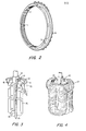
- FIG 2 shows an isometric view of a synchronizer ring, that is slightly frustoconical in shape (about 6 0- 30') and has an internal working surface that rubs against the carbo-nitride treated counterpiece.
- the threads 1 on the internal working surface of the ring provide scraping edges to quickly wipe the oil from the gear cone, and provide spiral grooves into which the oil can escape.
- the wiping grooves 2 aid in the removal of oil from the gear cone and allow for a rapid rise in the coefficient of friction.
- Three struts (not shown) are energizing elements that provide the initial load for indexing the ring. The struts ride in three ring slots 3 and move the ring into the indexed position. The slot width controls the amount of indexing.
- the ring chamfers 4 are angular surfaces on the periphery of the ring which align axially and circumferentially with the sleeve chamfers to establish a blocking action and produce synchronization.
- the cylindrical sputtering magnetron as shown in FIGS 1, 3, 4, and 5 comprises a bell jar 5, cooperating with a base plate 6 to form a sealed enclosure.
- the base plate 6 is provided with an evacuation port 7 that is connected to a suitable pumping device (not shown) and with an admission port 8 which is connected to a source of an appropriate inert gas such as argon.
- a magnetron mounting assembly 9 Through a circular opening in the top of the bell jar 5 is introduced a magnetron mounting assembly 9. On the outside of the mounting assembly 9 is a cylindrical target 10 which is made of the material to be sputtered (molybdenum) and which is the cathode. Next to the target 10 is a tubular sheath 11, which together with the target 10 forms an annular, tight chamber 12 (which is exaggerated in the drawing) between 0.1 and 0.3 mm. thick. The chamber is connected through the mounting assembly 9 to a supply 13 of high thermal conductivity gas (such as helium).
- high thermal conductivity gas such as helium
- a magnet assembly 14 which can be better seen in the perspective view of FIG 3, and is composed of a plurality of elongated magnets 15 and end magnets 16.
- the magnets are arranged such that the superposed magnetic flux forms a single closed-loop arch 17 (see FIG 4) extending in a meandering manner over the outer sputtering face of the cylindrical target 10.
- the upper end of the magnet assembly 14 is connected to the shaft of a motor 18, designed to slowly rotate the magnet assembly 14 in a back and forth movement which will cause uniform sputtering of the target 10 and a uniform coating on the substrate 19.
- the substrate 19 is the plurality of synchronizer rings stacked in a manner whereby every other ring is inverted and supported by mounting bracket 25, which is connected to ground, as is the bell jar 5.
- the coolant system has an admission port 21 and an evacuation port 22.
- the above apparatus also comprises a control circuit 23 which is connected on one side to the gas supply 13 and is connected on its output side to a switch 24.
- the control circuit 23 is designed to open the switch 24 at the termination of a sputtering run, as soon as the gas supply pressure undergoes a sudden change with respect to a predetermined valve resulting from the erosion of the metal target (as hereinafter described).
- the magnet assembly 14 (see FIG 3 and FIG 4) that is preferred to produce the best film has a small overall diameter (about 30 mm.) and consists of a plurality of elongated magnets 15 and end magnets 16 so situated relative to each other as to generate over the sputtering face of the target 10, a plurality of magnetic flux arch portions which define one closed loop arch path 17.
- the design ensures excellent target cooling, whatever the target length, since the liquid coolant can freely circulate along the longitudinal spaces.
- the cylindrical magnetron sputtering system will have means for axially rotating the magnet assembly 14 and the tubular target relative to each other (so as to cause a substantially uniform sputtering of said target, and improve target life) as well as for axially rotating the magnet assembly and the substrate relative to each other (so as to cause a substantially uniform-coating of said substrate).
- the magnets are designed for generating magnetic flux with arcuate end-portions which are connected in an alternate manner to the straight portions, so as to define a single closed-loop flux 17 extending in a meandering manner over the entire circumference of the sputtering face of the tubular target 10.
- the magnetron design ensures good uniformity of target sputtering and substrate coating because of the formation of a single meandering flux results in a plasma current which is proved to be relatively uniform along its whole path (because of the trapped electrons circulating along a single plasma).
- the rings to be coated will be stacked in a vertical and alternating manner, every other ring being inverted, so as to obtain a substantially continuous surface despite the slight taper of the rings.
- Stacks can have large numbers of rings, but for practical purposes are limited to about 60 to 75 rings, the combined height not to exceed about 60 cm.
- a heavy inert gas such as argon, is used as the gas atmosphere inside the vacuum chamber.
- the rings are initially subjected to ion bombardment by biasing them negatively at a more elevated argon pressure (10- 2 Torr) and grounding the magnetron. After about five minutes the polarity will be reversed, and the pressure reduced to about 5 x 10- 3 Torr, where magnetrons typically operate.
- the magnets are chosen to generate magnetic fields in the range of 300 to 800 Orsteds.
- cylindrical magnetron sputtering cathode and apparatus of the present invention may furthermore, in function of the different envisaged coating applications, be designed so as to assume one of the following configurations:
- the cylindrical magnetron cathode is arranged against a tubular intermediate support inserted between the tubular target and the magnetron, to define a tight chamber of low thickness to be used in a liquid cooling circuit.
- one of the essential features of the magnetron lies in the interposition of a relatively thin layer of a stagnant gas with a high thermal conductivity between the conventional liquid cooling circuit and the back of the sputtering target, the function of which is essentially of enabling the consumption of said target up to its piercing without causing any damage to the sputtering apparatus or to the ring substrates being coated, while further providing a sufficient target cooling throughout its sputtering.
- the pressure of said interposed stagnant gas layer (1 to 10 Torr) must be substantially higher than that in the vacuum bell jar of (10- 4 to 10- 2 Torr) so as to yield detectable pressure variations at the time of the target piercing. This pressure must not be too high, so as to avoid any risk of premature target piercing when the target becomes progressively thinner.
- the interposition of the stagnant gas layer between the sputtering target and the liquid coolant circuit furthermore ensures a sufficient target cooling throughout its sputtering, if the selected gas has a high thermal conductivity over the thin layer, which therefore allows a heat flow through said gas layer which will maintain the temperature of the sputtering target within an acceptable range.
- the deposition rate is from 0.5 to 1 micron per minute. To produce a film of about twenty microns, plus ion-etching and pumping down, will require about thirty minutes. A reduction in the power of the magnetron will reduce the deposition rate.
- Brass rings involve additional complications. Since brass is not ferromagnetic, a number of cylindrical magnetrons that could not be used with sintered iron or steel, are available. For example, the post magnetron will not work with iron or steel because the substrate shields the external magnetic field: the stack of magnetic rings shatters the external magnetic field. The working surface of brass is cold worked to induce hardness properties. When the brass ring is heated beyond 200 to 250 0 C, the ring will lose this induced hardness. Hence, one way to limit the substrate temperature is to cool the sputtered target, thereby minimizing the substrate heating by radiation. Another and very efficient way is to clamp the stack of rings within a water-cooled copper block, split in two or three segments, ensuring a good thermal contact against the external cylindrical surface of the rings.
- Tests were performed with a simulated manual transmission. Note that a 2-3-2 cycle consists of a shift from second gear to third gear and back again to second gear. An uncoated brass ring goes 8000 to 10,000 cycles.
- Two production Model T18 units were rebuilt by installing coated blocker rings. The ring substrate was bronze with a molybdenum coating on the internal working surface. The units were vehicle tested for shiftability and break-in, and were installed on a cycle stand and tested as follows:
Landscapes
- Engineering & Computer Science (AREA)
- General Engineering & Computer Science (AREA)
- Mechanical Engineering (AREA)
- Physical Vapour Deposition (AREA)
Priority Applications (1)
| Application Number | Priority Date | Filing Date | Title |
|---|---|---|---|
| EP81810311A EP0070952A1 (fr) | 1981-07-30 | 1981-07-30 | Anneau de synchronisation |
Applications Claiming Priority (1)
| Application Number | Priority Date | Filing Date | Title |
|---|---|---|---|
| EP81810311A EP0070952A1 (fr) | 1981-07-30 | 1981-07-30 | Anneau de synchronisation |
Publications (1)
| Publication Number | Publication Date |
|---|---|
| EP0070952A1 true EP0070952A1 (fr) | 1983-02-09 |
Family
ID=8188671
Family Applications (1)
| Application Number | Title | Priority Date | Filing Date |
|---|---|---|---|
| EP81810311A Withdrawn EP0070952A1 (fr) | 1981-07-30 | 1981-07-30 | Anneau de synchronisation |
Country Status (1)
| Country | Link |
|---|---|
| EP (1) | EP0070952A1 (fr) |
Cited By (5)
| Publication number | Priority date | Publication date | Assignee | Title |
|---|---|---|---|---|
| EP0159080A1 (fr) * | 1984-04-05 | 1985-10-23 | KOLBENSCHMIDT Aktiengesellschaft | Procédé de fabrication d'un anneau de synchro |
| EP0162393A1 (fr) * | 1984-05-14 | 1985-11-27 | SINTERSTAHL Gesellschaft m.b.H. | Embrayage ou frein à friction avec un élément de friction composé d'un support en tôle et d'une déposition d'une garniture de friction en matériau fritté |
| WO1986001863A1 (fr) * | 1984-09-20 | 1986-03-27 | Zahnradfabrik Friedrichshafen Ag | Bague recouverte d'une couche de materiau de friction sur sa partie conique |
| DE19841618C2 (de) * | 1998-09-11 | 2000-12-14 | Daimler Chrysler Ag | Thermisch gespritzter, verschleißfester Komfort - Synchronisierungsbelag |
| WO2010130366A1 (fr) * | 2009-05-14 | 2010-11-18 | Diehl Metall Stiftung & Co. Kg | Procédé de fabrication d'un élément constitutif d'un dispositif de synchronisation pour boîte de vitesses |
Citations (6)
| Publication number | Priority date | Publication date | Assignee | Title |
|---|---|---|---|---|
| DE1815372A1 (de) * | 1968-12-18 | 1970-07-02 | Daimler Benz Ag | Sperrsynchronisierte Schaltkupplung fuer Zahnrad-Wechselgetriebe,insbesondere von Kraftfahrzeugen |
| FR2073831A5 (fr) * | 1969-12-19 | 1971-10-01 | Porsche Kg | |
| DE2055345A1 (de) * | 1970-11-11 | 1972-05-18 | Zahnradfabrik Friedrichshafen | Synchronisierring in Schaltgetrieben |
| DE2433814B2 (de) * | 1974-07-13 | 1977-08-04 | Goetzewerke Friedrich Goetze Ag, 5093 Burscheid | Plasmaspritzpulver fuer verschleissfeste beschichtungen |
| GB1556664A (en) * | 1975-06-23 | 1979-11-28 | Volvo Ab | Method of and a device for feeding rings |
| US4221652A (en) * | 1975-04-10 | 1980-09-09 | Kabushiki Kaisha Tokuda Seisakusho | Sputtering device |
-
1981
- 1981-07-30 EP EP81810311A patent/EP0070952A1/fr not_active Withdrawn
Patent Citations (6)
| Publication number | Priority date | Publication date | Assignee | Title |
|---|---|---|---|---|
| DE1815372A1 (de) * | 1968-12-18 | 1970-07-02 | Daimler Benz Ag | Sperrsynchronisierte Schaltkupplung fuer Zahnrad-Wechselgetriebe,insbesondere von Kraftfahrzeugen |
| FR2073831A5 (fr) * | 1969-12-19 | 1971-10-01 | Porsche Kg | |
| DE2055345A1 (de) * | 1970-11-11 | 1972-05-18 | Zahnradfabrik Friedrichshafen | Synchronisierring in Schaltgetrieben |
| DE2433814B2 (de) * | 1974-07-13 | 1977-08-04 | Goetzewerke Friedrich Goetze Ag, 5093 Burscheid | Plasmaspritzpulver fuer verschleissfeste beschichtungen |
| US4221652A (en) * | 1975-04-10 | 1980-09-09 | Kabushiki Kaisha Tokuda Seisakusho | Sputtering device |
| GB1556664A (en) * | 1975-06-23 | 1979-11-28 | Volvo Ab | Method of and a device for feeding rings |
Cited By (5)
| Publication number | Priority date | Publication date | Assignee | Title |
|---|---|---|---|---|
| EP0159080A1 (fr) * | 1984-04-05 | 1985-10-23 | KOLBENSCHMIDT Aktiengesellschaft | Procédé de fabrication d'un anneau de synchro |
| EP0162393A1 (fr) * | 1984-05-14 | 1985-11-27 | SINTERSTAHL Gesellschaft m.b.H. | Embrayage ou frein à friction avec un élément de friction composé d'un support en tôle et d'une déposition d'une garniture de friction en matériau fritté |
| WO1986001863A1 (fr) * | 1984-09-20 | 1986-03-27 | Zahnradfabrik Friedrichshafen Ag | Bague recouverte d'une couche de materiau de friction sur sa partie conique |
| DE19841618C2 (de) * | 1998-09-11 | 2000-12-14 | Daimler Chrysler Ag | Thermisch gespritzter, verschleißfester Komfort - Synchronisierungsbelag |
| WO2010130366A1 (fr) * | 2009-05-14 | 2010-11-18 | Diehl Metall Stiftung & Co. Kg | Procédé de fabrication d'un élément constitutif d'un dispositif de synchronisation pour boîte de vitesses |
Similar Documents
| Publication | Publication Date | Title |
|---|---|---|
| US8036341B2 (en) | Stationary x-ray target and methods for manufacturing same | |
| JP6190590B2 (ja) | ベアリングコンポーネント、ベアリング、機械、およびベアリングコンポーネントの被覆方法 | |
| CA1128820A (fr) | Methode de modification de la composition et de la structure des alliages de revetement a teneur d'aluminium en cours de deposition de la phase gazeuse d'un metal | |
| KR100559285B1 (ko) | 캐소우드아크증착장치 | |
| US6669747B2 (en) | Grinding wheel with titanium aluminum nitride and hard lubricant coatings | |
| US7790003B2 (en) | Method for magnetron sputter deposition | |
| US20110073471A1 (en) | Method and apparatus for cathodic arc ion plasma deposition | |
| US20040038033A1 (en) | Dlc layer system and method for producing said layer system | |
| WO2018220067A1 (fr) | Ensemble cible pour évaporation sécurisée et économique de matériaux fragiles | |
| US6132565A (en) | Magnetron assembly equipped with traversing magnets and method of using | |
| EP0297779A2 (fr) | Cibles pour pulvérisation magnétron | |
| KR19990024031A (ko) | 캐소우드 아크 증착장치 | |
| JP4300762B2 (ja) | 炭素膜被覆物品及びその製造方法 | |
| US20040126492A1 (en) | Method and apparatus for using ion plasma deposition to produce coating | |
| WO2006020582A2 (fr) | Magnetron cylindrique a cible autonettoyante | |
| JP2015025466A (ja) | ピストンリング及びその製造方法 | |
| Spalvins | Survey of ion plating sources | |
| JP2739722B2 (ja) | ピストンリング | |
| GB2303640A (en) | Sliding member with film containing chromium and chromium nitride | |
| JPH06346226A (ja) | 工具の寿命向上方法および摩耗保護層を被覆した工具 | |
| RU2210620C1 (ru) | Способ ионно-плазменного нанесения многокомпонентных пленочных покрытий, мозаичная мишень для его осуществления и способ изготовления мишени | |
| KR100530545B1 (ko) | 캐소우드아크증착장치 | |
| EP1087033A1 (fr) | Cibles de pulvérisation à durée de vie allongée | |
| JP5880474B2 (ja) | 真空成膜装置 | |
| US4308126A (en) | Cathode sputtering apparatus |
Legal Events
| Date | Code | Title | Description |
|---|---|---|---|
| PUAI | Public reference made under article 153(3) epc to a published international application that has entered the european phase |
Free format text: ORIGINAL CODE: 0009012 |
|
| AK | Designated contracting states |
Designated state(s): AT BE CH DE FR GB IT LI LU NL SE |
|
| 17P | Request for examination filed |
Effective date: 19830527 |
|
| STAA | Information on the status of an ep patent application or granted ep patent |
Free format text: STATUS: THE APPLICATION HAS BEEN WITHDRAWN |
|
| 18W | Application withdrawn |
Withdrawal date: 19851219 |
|
| RIN1 | Information on inventor provided before grant (corrected) |
Inventor name: ZEGA, BOGDAN |