EP0071201A1 - Dispositif pour des plate-formes mobiles de parcage de véhicules - Google Patents
Dispositif pour des plate-formes mobiles de parcage de véhicules Download PDFInfo
- Publication number
- EP0071201A1 EP0071201A1 EP82106633A EP82106633A EP0071201A1 EP 0071201 A1 EP0071201 A1 EP 0071201A1 EP 82106633 A EP82106633 A EP 82106633A EP 82106633 A EP82106633 A EP 82106633A EP 0071201 A1 EP0071201 A1 EP 0071201A1
- Authority
- EP
- European Patent Office
- Prior art keywords
- platform
- platforms
- coupling member
- coupling
- contacts
- Prior art date
- Legal status (The legal status is an assumption and is not a legal conclusion. Google has not performed a legal analysis and makes no representation as to the accuracy of the status listed.)
- Granted
Links
- 238000010168 coupling process Methods 0.000 claims abstract description 46
- 230000008878 coupling Effects 0.000 claims abstract description 42
- 238000005859 coupling reaction Methods 0.000 claims abstract description 42
- 238000010276 construction Methods 0.000 description 2
- 238000004519 manufacturing process Methods 0.000 description 2
- 238000000034 method Methods 0.000 description 2
- 230000015572 biosynthetic process Effects 0.000 description 1
- 238000006073 displacement reaction Methods 0.000 description 1
Images



Classifications
-
- E—FIXED CONSTRUCTIONS
- E04—BUILDING
- E04H—BUILDINGS OR LIKE STRUCTURES FOR PARTICULAR PURPOSES; SWIMMING OR SPLASH BATHS OR POOLS; MASTS; FENCING; TENTS OR CANOPIES, IN GENERAL
- E04H6/00—Buildings for parking cars, rolling-stock, aircraft, vessels or like vehicles, e.g. garages
- E04H6/08—Garages for many vehicles
- E04H6/12—Garages for many vehicles with mechanical means for shifting or lifting vehicles
- E04H6/30—Garages for many vehicles with mechanical means for shifting or lifting vehicles with means for transport in horizontal direction only
- E04H6/36—Garages for many vehicles with mechanical means for shifting or lifting vehicles with means for transport in horizontal direction only characterised by use of freely-movable dollies
Definitions
- the invention relates to a device on couplings for a plurality of displaceable platforms for parking motor vehicles, a platform having a drive at the end of a row of platforms to couple the row and then to form a gap between two platforms, with contacts and couplings between the platforms.
- movable platforms are provided on this street, on which motor vehicles can be parked.
- the movability makes it possible for the parking spaces to remain accessible on both sides of the street.
- the displaceable platforms are guided, for example, by rails and, in order to reduce the manufacturing outlay, it is known to provide only the platform at the end of the row with a drive in a row of such platforms.
- the procedure is generally such that all platforms are pushed together by means of the driven platform, the individual platforms being electrically and mechanically coupled to one another. When moving backwards, a gap is then formed between two platforms by suitable means.
- the invention has set itself the task of improving the means for mechanical and electrical coupling of the individual platforms.
- the invention is based on a device of the type described in the introduction and proposes that the coupling members and the contacts on each side of the platform be connected to form a structural unit.
- the invention achieves that the alignment effect achieved by the coupling can also be used with the electrical contacts without any special manufacturing and assembly effort. This makes plug connections completely avoidable.
- Contact forces that are necessary for the coupling, as well as displacement paths of the coupling members relative to one another, can also be used to bring about the good electrical contacts.
- each platform has a particular structural unit on one side and on the other side, with two structural units of adjacent platforms each interacting. To implement the invention it is not necessary that all coupling elements or all contacts are combined in the structural unit, although this usually brings the optimum advantage.
- the units of all platforms in a row will be of the same design. However, it is clear that, for example, the number of electrical contacts required on the last platform in a row is considerably less than the corresponding contacts on the first platform to be coupled. In some cases it may be advisable to use different units in a row.
- the invention further proposes that a pin-like coupling member is provided which is surrounded by a contact carrier.
- This contact carrier is movably mounted in particular on the coupling member.
- the contact carrier preferably has resilient contact pins which interact with contact plates of the assembly of the other platform. It has been found that practically no faults occur with this type of construction even under unfavorable operating conditions. The contact pressures are comparatively high. When driving, however, no driving forces are generated. The arrangement is largely insensitive to movements perpendicular to the coupling direction.
- the resilient contact pins it is advisable for the resilient contact pins to surround the peg-shaped coupling member in a circle.
- the invention further proposes that the pin-like coupling member has a coupling groove for the actuatable coupling member of the other platform on its front part.
- This coupling member is preferably designed as a folding latch. A spring tries to move this latch bolt into the open position. An electromagnet is provided to reach the closed position.
- Such a construction has the advantage that jamming phenomena that lead to an unintentional entrainment of a platform are largely excluded.
- the coupling pin is preferably arranged on the driven or coupled platform.
- a foldable safety bar on the platform to be coupled completes the arrangement according to the invention.
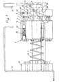
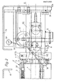
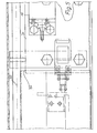
- the platform 11 or 12 can have a size that allows the parking of one or more vehicles. Two or more platforms can be arranged in a row of platforms. In the illustration in the drawing, it is assumed that the left platform or platform 11 is the platform that has the drive or that is already connected to the correspondingly driven platform. The other platform 12 is the platform to be coupled.
- the peg-like coupling member 1 is attached to the platform 11. 2 and 3, the end 21 of the coupling member 1 already protrudes into the other coupling member.
- the coupling member 1 has a groove 13 in which, when engaged, the other coupling member, namely the latch 2, engages.
- the contact carrier 7 On the coupling member 1, the contact carrier 7 is movable, which has a substantially cylindrical shape. This contact carrier is under the action of the spring 23 which presses the contact carrier 7 against the collar 25 on the link 1.
- the contact carrier has a plurality of bores 27, for example ten such bores, in each of which the contact pins 9 with the contacts 3 are movably guided. These contact pins 9 are under the action of the springs 29.
- the whole, consisting of the contact carrier 7 and the coupling member 1, 5 is attached to the platform 11 at 31.
- the other assembly 6 on the other platform 12 essentially consists of the receiving bore 22 in the sleeve 32, which carries at its front end the flange 26 with the contact plates 10 for the contacts 4.
- the folding latch 2, which is movable about the joint 8, also belongs to the structural unit 6.
- the folding latch 14 is under the action of the spring 16 and the electromagnet 18, which parts can also be included in the structural unit, all of these parts being arranged on the mounting plate 24 which is attached to the platform 12.
- either the electromagnet 18 of the platform 12 in question is acted upon or not, so that the latch bolt 14 moves into the closed position or remains in the open position.
- Another advantage of the invention is that the number of switching contacts required remains low in the arrangement made.
- a safety bar 20 is also movably mounted on the platform 12 around the joint 30. This safety bar prevents accidents during the coupling process. If the safety bar is actuated because an obstacle protrudes into the gap between the platforms, it gives a stop signal after the corresponding circuits have been formed by means of contacts 3, 4 when the two platforms are first contacted. If the safety bar is only adjusted by the platform 11, the stop signal is omitted.
Landscapes
- Engineering & Computer Science (AREA)
- Architecture (AREA)
- Mechanical Engineering (AREA)
- Civil Engineering (AREA)
- Structural Engineering (AREA)
- Refuge Islands, Traffic Blockers, Or Guard Fence (AREA)
- Linear Motors (AREA)
- Vehicle Cleaning, Maintenance, Repair, Refitting, And Outriggers (AREA)
Priority Applications (1)
| Application Number | Priority Date | Filing Date | Title |
|---|---|---|---|
| AT82106633T ATE15826T1 (de) | 1981-07-23 | 1982-07-22 | Vorrichtung an verschiebbaren plattformen zum abstellen von kraftfahrzeugen. |
Applications Claiming Priority (2)
| Application Number | Priority Date | Filing Date | Title |
|---|---|---|---|
| DE8121553U | 1981-07-23 | ||
| DE8121553U DE8121553U1 (de) | 1981-07-23 | 1981-07-23 | "Vorrichtung an verschiebbaren Plattformen zum Abstellen von Kraftfahrzeugen" |
Publications (2)
| Publication Number | Publication Date |
|---|---|
| EP0071201A1 true EP0071201A1 (fr) | 1983-02-09 |
| EP0071201B1 EP0071201B1 (fr) | 1985-09-25 |
Family
ID=6729680
Family Applications (1)
| Application Number | Title | Priority Date | Filing Date |
|---|---|---|---|
| EP82106633A Expired EP0071201B1 (fr) | 1981-07-23 | 1982-07-22 | Dispositif pour des plate-formes mobiles de parcage de véhicules |
Country Status (3)
| Country | Link |
|---|---|
| EP (1) | EP0071201B1 (fr) |
| AT (1) | ATE15826T1 (fr) |
| DE (1) | DE8121553U1 (fr) |
Cited By (1)
| Publication number | Priority date | Publication date | Assignee | Title |
|---|---|---|---|---|
| DE19962542A1 (de) * | 1999-12-23 | 2001-07-12 | Woehr Otto Gmbh | Plattform zur Aufnahme eines Kraftfahrzeuges |
Citations (4)
| Publication number | Priority date | Publication date | Assignee | Title |
|---|---|---|---|---|
| US1887667A (en) * | 1929-04-02 | 1932-11-15 | Mechanical Transfer Car Corp | Means of parking cars in garages |
| FR1400536A (fr) * | 1964-04-15 | 1965-05-28 | Realisations Ind Soc Et | Installation de garage pour véhicules |
| BE712980A (fr) * | 1968-01-31 | 1968-07-31 | ||
| FR2457796A1 (fr) * | 1979-06-01 | 1980-12-26 | Scharfenbergkupplung Gmbh | Dispositif d'accouplement rigide automatique pour vehicules de tete |
-
1981
- 1981-07-23 DE DE8121553U patent/DE8121553U1/de not_active Expired
-
1982
- 1982-07-22 AT AT82106633T patent/ATE15826T1/de not_active IP Right Cessation
- 1982-07-22 EP EP82106633A patent/EP0071201B1/fr not_active Expired
Patent Citations (4)
| Publication number | Priority date | Publication date | Assignee | Title |
|---|---|---|---|---|
| US1887667A (en) * | 1929-04-02 | 1932-11-15 | Mechanical Transfer Car Corp | Means of parking cars in garages |
| FR1400536A (fr) * | 1964-04-15 | 1965-05-28 | Realisations Ind Soc Et | Installation de garage pour véhicules |
| BE712980A (fr) * | 1968-01-31 | 1968-07-31 | ||
| FR2457796A1 (fr) * | 1979-06-01 | 1980-12-26 | Scharfenbergkupplung Gmbh | Dispositif d'accouplement rigide automatique pour vehicules de tete |
Cited By (2)
| Publication number | Priority date | Publication date | Assignee | Title |
|---|---|---|---|---|
| DE19962542A1 (de) * | 1999-12-23 | 2001-07-12 | Woehr Otto Gmbh | Plattform zur Aufnahme eines Kraftfahrzeuges |
| DE19962542B4 (de) * | 1999-12-23 | 2004-02-05 | Otto Wöhr Gmbh | Plattform zur Aufnahme eines Kraftfahrzeuges |
Also Published As
| Publication number | Publication date |
|---|---|
| DE8121553U1 (de) | 1981-12-24 |
| ATE15826T1 (de) | 1985-10-15 |
| EP0071201B1 (fr) | 1985-09-25 |
Similar Documents
| Publication | Publication Date | Title |
|---|---|---|
| DE2730660A1 (de) | Elektrische kupplungsvorrichtung | |
| EP0805366A1 (fr) | Connecteur | |
| DE69601017T2 (de) | Automatisch einsteckbarer elektrischer Verbinder | |
| EP0982215B1 (fr) | Ensemble pour véhicule ferroviaire, composé d'un accouplement central et d'un accouplement de câbles électriques | |
| CH645577A5 (de) | Mechanische mittelpufferkupplung fuer schienenfahrzeuge. | |
| DE19600314C2 (de) | Relais mit zwangsgeführten Kontaktsätzen | |
| DE10006922C2 (de) | Steckverbinder | |
| DE69328466T2 (de) | Verbinder | |
| DE19910027C2 (de) | Steckverbinder mit hebelbetätigtem Schieber | |
| DE3013835A1 (de) | Verriegelungsvorrichtung fuer zwei druckknoepfe | |
| EP0071201B1 (fr) | Dispositif pour des plate-formes mobiles de parcage de véhicules | |
| DE69303391T2 (de) | Verriegelungsmechanismus für blindsteckbare elektrische Verbinder | |
| DE68911187T2 (de) | Verbindungssystem für modulare Autotürplatten. | |
| EP4183658B1 (fr) | Dispositif de verrouillage / déverrouillage d'un coupleur de véhicule ferroviaire | |
| EP1458938B1 (fr) | Chargeur frontal a dispositif d'accouplement automatique | |
| DE69806845T2 (de) | Halbautomatische Verbindung zusammen mit mechanischer Kupplung | |
| DE3146617A1 (de) | "vorrichtung an verschiebbaren plattformen zum abstellen von kraftfahrzeugen" | |
| DE3312657C2 (fr) | ||
| DE102020130561A1 (de) | Stirnplatte für einen Schienenfahrzeugkupplungskopf, Schienenfahrzeugkupplungskopf und Verfahren zum Herstellen einer Stirnplatte und eines Schienenfahrzeugkupplungskopfes | |
| DE1810872C3 (de) | Kabelkupplung zum selbsttätigen Mitkuppeln der elektrischen Leitungen von Eisenbahnwagen | |
| DE102019125744B4 (de) | Ladedose | |
| DE3690115C2 (de) | Elektrischer Schalter mit Zwangsöffnung seiner Ruhekontakte | |
| EP1127768B1 (fr) | Accouplement pour câbles électriques avec un dispositif de verrouillage, pour véhicule ferroviaire | |
| EP0603559A1 (fr) | Attelage de remorque amovible | |
| DE102018126470A1 (de) | Zugkupplungsadapter |
Legal Events
| Date | Code | Title | Description |
|---|---|---|---|
| PUAI | Public reference made under article 153(3) epc to a published international application that has entered the european phase |
Free format text: ORIGINAL CODE: 0009012 |
|
| AK | Designated contracting states |
Designated state(s): AT BE CH FR GB IT LI LU NL SE |
|
| 17P | Request for examination filed |
Effective date: 19830416 |
|
| ITF | It: translation for a ep patent filed | ||
| GRAA | (expected) grant |
Free format text: ORIGINAL CODE: 0009210 |
|
| AK | Designated contracting states |
Designated state(s): AT BE CH FR GB IT LI LU NL SE |
|
| REF | Corresponds to: |
Ref document number: 15826 Country of ref document: AT Date of ref document: 19851015 Kind code of ref document: T |
|
| ET | Fr: translation filed | ||
| PG25 | Lapsed in a contracting state [announced via postgrant information from national office to epo] |
Ref country code: AT Effective date: 19860722 |
|
| PG25 | Lapsed in a contracting state [announced via postgrant information from national office to epo] |
Ref country code: SE Effective date: 19860723 |
|
| PLBE | No opposition filed within time limit |
Free format text: ORIGINAL CODE: 0009261 |
|
| STAA | Information on the status of an ep patent application or granted ep patent |
Free format text: STATUS: NO OPPOSITION FILED WITHIN TIME LIMIT |
|
| PG25 | Lapsed in a contracting state [announced via postgrant information from national office to epo] |
Ref country code: LU Free format text: LAPSE BECAUSE OF NON-PAYMENT OF DUE FEES Effective date: 19860731 Ref country code: LI Effective date: 19860731 Ref country code: CH Effective date: 19860731 Ref country code: BE Effective date: 19860731 |
|
| 26N | No opposition filed | ||
| BERE | Be: lapsed |
Owner name: KLAUS KASPAR Effective date: 19860731 |
|
| PG25 | Lapsed in a contracting state [announced via postgrant information from national office to epo] |
Ref country code: NL Effective date: 19870201 |
|
| NLV4 | Nl: lapsed or anulled due to non-payment of the annual fee | ||
| PG25 | Lapsed in a contracting state [announced via postgrant information from national office to epo] |
Ref country code: FR Free format text: LAPSE BECAUSE OF NON-PAYMENT OF DUE FEES Effective date: 19870331 |
|
| REG | Reference to a national code |
Ref country code: CH Ref legal event code: PL |
|
| GBPC | Gb: european patent ceased through non-payment of renewal fee | ||
| REG | Reference to a national code |
Ref country code: FR Ref legal event code: ST |
|
| PG25 | Lapsed in a contracting state [announced via postgrant information from national office to epo] |
Ref country code: GB Effective date: 19881121 |
|
| EUG | Se: european patent has lapsed |
Ref document number: 82106633.9 Effective date: 19870609 |