EP0071208A2 - Potentiomètre rotatif - Google Patents
Potentiomètre rotatif Download PDFInfo
- Publication number
- EP0071208A2 EP0071208A2 EP82106673A EP82106673A EP0071208A2 EP 0071208 A2 EP0071208 A2 EP 0071208A2 EP 82106673 A EP82106673 A EP 82106673A EP 82106673 A EP82106673 A EP 82106673A EP 0071208 A2 EP0071208 A2 EP 0071208A2
- Authority
- EP
- European Patent Office
- Prior art keywords
- rotary
- carrier plate
- driver
- rotary shaft
- rotary potentiometer
- Prior art date
- Legal status (The legal status is an assumption and is not a legal conclusion. Google has not performed a legal analysis and makes no representation as to the accuracy of the status listed.)
- Withdrawn
Links
- 230000008878 coupling Effects 0.000 claims description 7
- 238000010168 coupling process Methods 0.000 claims description 7
- 238000005859 coupling reaction Methods 0.000 claims description 7
- 239000000919 ceramic Substances 0.000 claims description 3
- 239000004020 conductor Substances 0.000 claims description 3
- 239000011810 insulating material Substances 0.000 claims description 3
- 239000000758 substrate Substances 0.000 claims description 3
- 238000004519 manufacturing process Methods 0.000 description 2
- 238000000034 method Methods 0.000 description 1
Images

Classifications
-
- H—ELECTRICITY
- H01—ELECTRIC ELEMENTS
- H01C—RESISTORS
- H01C1/00—Details
- H01C1/01—Mounting; Supporting
-
- H—ELECTRICITY
- H01—ELECTRIC ELEMENTS
- H01C—RESISTORS
- H01C10/00—Adjustable resistors
- H01C10/30—Adjustable resistors the contact sliding along resistive element
- H01C10/32—Adjustable resistors the contact sliding along resistive element the contact moving in an arcuate path
- H01C10/34—Adjustable resistors the contact sliding along resistive element the contact moving in an arcuate path the contact or the associated conducting structure riding on collector formed as a ring or portion thereof
-
- H—ELECTRICITY
- H01—ELECTRIC ELEMENTS
- H01C—RESISTORS
- H01C10/00—Adjustable resistors
- H01C10/30—Adjustable resistors the contact sliding along resistive element
- H01C10/32—Adjustable resistors the contact sliding along resistive element the contact moving in an arcuate path
- H01C10/36—Adjustable resistors the contact sliding along resistive element the contact moving in an arcuate path structurally combined with switching arrangements
Definitions
- the invention relates to a rotary potentiometer with an inner ring-shaped loop and. an outer, approximately horseshoe-shaped resistance track provided with a plate-shaped support body, the connecting ends of the grinder and resistance track being arranged on a side edge of the support plate, with a sliding contact which is adjustable by means of a driver by means of an actuator.
- a rotary potentiometer of this type has become known from DE-GM 19 29 588. This is used as a layer trim resistor and has a sliding contact that is connected in a rotationally locking manner to a flange tube. To hold the sliding contact on the carrier plate, the flange tube passes through a central hole in the carrier plate and is held on the sliding contact by means of rivets. To actuate the sliding contact, an adjusting shaft can be inserted into the flange tube or into the sliding contact in a rotationally locking manner. Since the inner annular wiper track is also designed as a resistance track, its electrical connection contact must be provided as a separate contact part and is electrically connected to the wiper contact by means of the flange tube and held on the carrier plate.
- the object of the invention is to provide a rotary potentiometer which should be able to be produced using simple components and whose assembly can be carried out without special riveting processes or other complex work steps. At the same time, the rotary potentiometer should be easy to couple with an actuator.
- the driver consisting of insulating material contains a rotary shaft which is connected via a radial web to the periphery of the driver such that the rotary shaft is axially movable and that the free end of the rotary shaft facing the carrier plate is provided by a longitudinal slot split to a rotatable latching connection in a central bore of the carrier plate, while the opposite free end of the rotary shaft can be coupled to the actuator.
- the actuator is the selector shaft of a rotary switch and the rotary potentiometer can be pushed into a fixed mounting of the rotary switch at the end of the selector shaft transversely to its longitudinal axis and can be snapped into a coupling bore of the selector shaft with its rotary shaft by means of an inclined surface formed on its free end.
- the carrier plate is rectangular and can be inserted into a slot-shaped mounting of the rotary switch.
- a further embodiment is that the sliding contact is a band-shaped leaf spring, which lies tangentially to the rotating shaft with its two ends on pins of the driver and is pressed with a central transverse rib against the sliding track and the resistance track.
- the leaf spring is formed with multiple fingers through longitudinal slots.
- the driver is designed as a round body and that on both sides of the connecting ends of the slider and resistance track on the side edge of the carrier plate further terminal ends are arranged, of conductor tracks attached to the carrier plate for electronic attachable to the carrier plate outside the driver Components.
- the support plate is expediently connected to a printed circuit board with its side edge provided with the connection ends and can be inserted perpendicular to the latter into the mounting of the rotary switch.
- the carrier plate is a thick-film ceramic-based substrate plate.
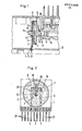
- the rotary potentiometer consists of a carrier plate 1 with an inner annular slider track .2 and an outer approximately horseshoe-shaped resistance track 3, the connection ends are led out to one side edge of the carrier plate 1 as connections 4 and 5.
- the wiper track 2 and resistance track 3 are connected to one another by a wiper contact 6, which is arranged in a driver 7 in a rotationally locking manner.
- An insulating material part is provided as the driver 7, which is designed essentially as a round flat disc and receives the sliding contact 6 in an inner recess.
- the driver 7 contains a rotary shaft 8 which is connected via a radial web 9 'to the periphery of the driver such that the rotary shaft 8 is axially elastically movable.
- the rotary shaft 8 is split at its free end facing the support plate 1 by a longitudinal slot 10 and penetrates a central bore 11 in the support plate 1, behind which it can be locked with molded-on locking shoulders 12.
- the locking shoulders 12 are always slightly pressed against the carrier plate 1 by the elastic design of the radial web 9.
- the rotary shaft 8 is rotatable in the bore 11 of the carrier plate 1.
- the other, opposite free end 13 of the rotary shaft 8 can be coupled to an actuator 14.
- this free end 13 can be designed as a profiled pin and can be held in a rotationally locking manner in a coupling bore 17 of the actuator 14.
- the actuator 14 is the control shaft of a rotary switch and the potentiometer is held at the end of the control shaft transversely to its longitudinal axis in a fixed bearing 15 of the switch housing.
- the rotary potentiometer is connected with its side edge provided with the connection ends 4, 5 to a printed circuit board 22 and is perpendicular to the latter.
- the rotary potentiometer can be inserted into the slot-like bearing 15 of the switch housing when the circuit board 22 is inserted into the switch housing, the rotary shaft 8 engaging with its coupling attachment at the free end 13 in the coupling bore 17 of the switching shaft.
- This will be temporary by the elastic design of the radial web 9, the rotary shaft 8 axially pushed away.
- the inclusion of this free end 13 in the selector shaft 14 is facilitated by an inclined surface 16 molded onto the free end 13.
- the free end 13 of the rotary shaft 8 of the rotary potentiometer can also be provided with a coupling bore instead of a pin, in which case a corresponding coupling pin must then be formed on the actuator 14.
- the sliding contact 6 is designed as a band-shaped leaf spring and is easy to manufacture as such. This is tangential to the rotary shaft 8 in the driver 7 and is supported at its two ends on the pin 18 of the driver 7 and pressed with a central transverse rib 19 against the grinder track 2 and resistance bars 3.
- the leaf spring 6 is formed with multiple fingers by longitudinal slots 20.
- 7 electronic components can be accommodated on the carrier plate 1 outside the driver. Due to the rectangular design of the carrier plate 1, such electronic components can be attached to the remaining corner pieces of the carrier plate 1 as well as on the side of the carrier plate 1 opposite the carrier 7 in addition to the round driver 7.
- the carrier plate 1 can be made of hard paper in a known manner as a printed circuit board with the corresponding resistance tracks. In a special way, however, it is designed as a thick-film substrate plate on a ceramic basis.
Landscapes
- Engineering & Computer Science (AREA)
- Microelectronics & Electronic Packaging (AREA)
- Adjustable Resistors (AREA)
- Holding Or Fastening Of Disk On Rotational Shaft (AREA)
- Display Devices Of Pinball Game Machines (AREA)
- Ignition Installations For Internal Combustion Engines (AREA)
Applications Claiming Priority (2)
| Application Number | Priority Date | Filing Date | Title |
|---|---|---|---|
| DE3130273 | 1981-07-31 | ||
| DE3130273A DE3130273C2 (de) | 1981-07-31 | 1981-07-31 | Drehpotentiometer |
Publications (2)
| Publication Number | Publication Date |
|---|---|
| EP0071208A2 true EP0071208A2 (fr) | 1983-02-09 |
| EP0071208A3 EP0071208A3 (fr) | 1983-09-28 |
Family
ID=6138214
Family Applications (1)
| Application Number | Title | Priority Date | Filing Date |
|---|---|---|---|
| EP82106673A Withdrawn EP0071208A3 (fr) | 1981-07-31 | 1982-07-23 | Potentiomètre rotatif |
Country Status (3)
| Country | Link |
|---|---|
| EP (1) | EP0071208A3 (fr) |
| DE (1) | DE3130273C2 (fr) |
| NO (1) | NO152391C (fr) |
Cited By (2)
| Publication number | Priority date | Publication date | Assignee | Title |
|---|---|---|---|---|
| EP0254252A3 (en) * | 1986-07-22 | 1989-11-15 | Wilhelm Ruf Kg | Rotary potentiometer, in particular for use as an angular position sensor for the rotary positioning of a shaft |
| CN111627629A (zh) * | 2019-02-28 | 2020-09-04 | 格德斯控股两合公司 | 电子旋转开关以及电连续式加热器 |
Family Cites Families (5)
| Publication number | Priority date | Publication date | Assignee | Title |
|---|---|---|---|---|
| US3567876A (en) * | 1968-09-23 | 1971-03-02 | C T S Corp | Combination variable resistance and electrical switch actuating means |
| US4035759A (en) * | 1973-03-19 | 1977-07-12 | Cts Corporation | Electrical control having an insulated shaft extension |
| US4090167A (en) * | 1977-01-31 | 1978-05-16 | Teccor Electronics, Inc. | Push switch and potentiometer assembly |
| GB2028594B (en) * | 1978-08-22 | 1982-09-02 | Standard Telephones Cables Ltd | Miniature potentiometer |
| US4225845A (en) * | 1978-08-30 | 1980-09-30 | North American Philips Corporation | Open frame single turn potentiometer with helical coil spring wiper and resilient member |
-
1981
- 1981-07-31 DE DE3130273A patent/DE3130273C2/de not_active Expired
-
1982
- 1982-07-23 EP EP82106673A patent/EP0071208A3/fr not_active Withdrawn
- 1982-07-30 NO NO822622A patent/NO152391C/no unknown
Cited By (3)
| Publication number | Priority date | Publication date | Assignee | Title |
|---|---|---|---|---|
| EP0254252A3 (en) * | 1986-07-22 | 1989-11-15 | Wilhelm Ruf Kg | Rotary potentiometer, in particular for use as an angular position sensor for the rotary positioning of a shaft |
| CN111627629A (zh) * | 2019-02-28 | 2020-09-04 | 格德斯控股两合公司 | 电子旋转开关以及电连续式加热器 |
| CN111627629B (zh) * | 2019-02-28 | 2023-02-10 | 格德斯控股两合公司 | 电子旋转开关以及电连续式加热器 |
Also Published As
| Publication number | Publication date |
|---|---|
| NO152391C (no) | 1985-09-18 |
| NO822622L (no) | 1983-02-01 |
| EP0071208A3 (fr) | 1983-09-28 |
| DE3130273A1 (de) | 1983-03-17 |
| DE3130273C2 (de) | 1983-11-10 |
| NO152391B (no) | 1985-06-10 |
Similar Documents
| Publication | Publication Date | Title |
|---|---|---|
| DE19721514C2 (de) | Dreh-Tast-Schalter | |
| DE3040546C2 (de) | Codierschalter | |
| DE2617186A1 (de) | Elektrischer schalter | |
| DE1920784A1 (de) | Schiebeschalter fuer Geraete mit einem von einer Isolierstoffplatte getragenen Leiternetz | |
| DE2806713C3 (de) | Elektrischer Schalter mit in Durchbrüchen angeordneten feststehenden Kontakten | |
| DE1937989B2 (de) | Trimmpotentiometer für elektronische Schaltungen | |
| EP0196622B1 (fr) | Potentiomètre rotatif et à curseur (interrupteur à prises) | |
| DE2708725A1 (de) | Variabler elektrischer widerstand | |
| EP0071208A2 (fr) | Potentiomètre rotatif | |
| EP0076292B1 (fr) | Contact electrique, notamment pour circuits imprimes de petits appareils electriques | |
| DE2831204C2 (de) | Miniatur-Stufenschalter | |
| DE2633800A1 (de) | Gedruckte schaltungsplatte und damit ausgestatteter drehschalter | |
| DE2441469C3 (de) | Elektrischer Drehschalter in geschlossener Bauweise | |
| EP0223968A2 (fr) | Interrupteur électrique rotatif | |
| DE102007009006B4 (de) | Tastschalter für ein Kraftfahrzeug | |
| DE3136471C2 (de) | Drehschalter | |
| DE8504297U1 (de) | Drehschaltereinheit für ein elektrisches Handgerät | |
| DE2921753A1 (de) | Drehschalter | |
| DE3329827A1 (de) | Tastenschalter | |
| DE2534126A1 (de) | Leiterplatte mit einer gedruckten schaltung | |
| DE2016992C3 (de) | Schaltvorrichtung mit geringem Rastmoment | |
| DE29703892U1 (de) | Potentiometer in Dickschichttechnik, Leiterplatte und Schleifer hierfür | |
| DE3623539C2 (de) | Drehschalter | |
| WO2000025392A1 (fr) | Element de codage | |
| DE7812017U1 (de) | Wähltastatur |
Legal Events
| Date | Code | Title | Description |
|---|---|---|---|
| PUAI | Public reference made under article 153(3) epc to a published international application that has entered the european phase |
Free format text: ORIGINAL CODE: 0009012 |
|
| AK | Designated contracting states |
Designated state(s): BE FR GB SE |
|
| PUAL | Search report despatched |
Free format text: ORIGINAL CODE: 0009013 |
|
| AK | Designated contracting states |
Designated state(s): BE FR GB SE |
|
| 17P | Request for examination filed |
Effective date: 19840229 |
|
| STAA | Information on the status of an ep patent application or granted ep patent |
Free format text: STATUS: THE APPLICATION IS DEEMED TO BE WITHDRAWN |
|
| 18D | Application deemed to be withdrawn |
Effective date: 19860513 |
|
| RIN1 | Information on inventor provided before grant (corrected) |
Inventor name: SCHULTZ, WILFRIED |