EP0071217A2 - Verfahren zum Ausbessern von Unterwasserpfählen und Unterwasserummantelung dafür - Google Patents
Verfahren zum Ausbessern von Unterwasserpfählen und Unterwasserummantelung dafür Download PDFInfo
- Publication number
- EP0071217A2 EP0071217A2 EP82106693A EP82106693A EP0071217A2 EP 0071217 A2 EP0071217 A2 EP 0071217A2 EP 82106693 A EP82106693 A EP 82106693A EP 82106693 A EP82106693 A EP 82106693A EP 0071217 A2 EP0071217 A2 EP 0071217A2
- Authority
- EP
- European Patent Office
- Prior art keywords
- annular space
- jacket
- piling
- epoxy resin
- semi
- Prior art date
- Legal status (The legal status is an assumption and is not a legal conclusion. Google has not performed a legal analysis and makes no representation as to the accuracy of the status listed.)
- Granted
Links
- 238000000034 method Methods 0.000 title claims abstract description 37
- 239000003822 epoxy resin Substances 0.000 claims abstract description 72
- 229920000647 polyepoxide Polymers 0.000 claims abstract description 72
- 239000000203 mixture Substances 0.000 claims abstract description 60
- 230000013011 mating Effects 0.000 claims abstract description 52
- 238000002347 injection Methods 0.000 claims abstract description 32
- 239000007924 injection Substances 0.000 claims abstract description 32
- 238000007789 sealing Methods 0.000 claims abstract description 32
- 239000000463 material Substances 0.000 claims abstract description 26
- 239000004567 concrete Substances 0.000 claims abstract description 19
- 238000013022 venting Methods 0.000 claims abstract description 16
- 239000002023 wood Substances 0.000 claims abstract description 11
- XLYOFNOQVPJJNP-UHFFFAOYSA-N water Substances O XLYOFNOQVPJJNP-UHFFFAOYSA-N 0.000 claims abstract description 8
- 229910000831 Steel Inorganic materials 0.000 claims abstract description 7
- 239000010959 steel Substances 0.000 claims abstract description 7
- 230000008878 coupling Effects 0.000 claims description 16
- 238000010168 coupling process Methods 0.000 claims description 16
- 238000005859 coupling reaction Methods 0.000 claims description 16
- 229910000746 Structural steel Inorganic materials 0.000 claims description 11
- 239000004094 surface-active agent Substances 0.000 claims description 5
- VVQNEPGJFQJSBK-UHFFFAOYSA-N Methyl methacrylate Chemical compound COC(=O)C(C)=C VVQNEPGJFQJSBK-UHFFFAOYSA-N 0.000 claims description 3
- 229920005372 Plexiglas® Polymers 0.000 claims description 3
- 230000009471 action Effects 0.000 claims description 3
- 229920005989 resin Polymers 0.000 claims description 3
- 239000011347 resin Substances 0.000 claims description 3
- 238000010926 purge Methods 0.000 claims description 2
- 229920003023 plastic Polymers 0.000 description 10
- 239000004033 plastic Substances 0.000 description 9
- 239000000758 substrate Substances 0.000 description 5
- 239000006261 foam material Substances 0.000 description 4
- 230000004048 modification Effects 0.000 description 4
- 238000012986 modification Methods 0.000 description 4
- 239000012528 membrane Substances 0.000 description 3
- 239000004698 Polyethylene Substances 0.000 description 2
- IISBACLAFKSPIT-UHFFFAOYSA-N bisphenol A Chemical compound C=1C=C(O)C=CC=1C(C)(C)C1=CC=C(O)C=C1 IISBACLAFKSPIT-UHFFFAOYSA-N 0.000 description 2
- DQXBYHZEEUGOBF-UHFFFAOYSA-N but-3-enoic acid;ethene Chemical compound C=C.OC(=O)CC=C DQXBYHZEEUGOBF-UHFFFAOYSA-N 0.000 description 2
- 239000003795 chemical substances by application Substances 0.000 description 2
- 239000005038 ethylene vinyl acetate Substances 0.000 description 2
- 229920001200 poly(ethylene-vinyl acetate) Polymers 0.000 description 2
- 229920000768 polyamine Polymers 0.000 description 2
- -1 polyethylene Polymers 0.000 description 2
- 229920000573 polyethylene Polymers 0.000 description 2
- 239000003566 sealing material Substances 0.000 description 2
- AHDSRXYHVZECER-UHFFFAOYSA-N 2,4,6-tris[(dimethylamino)methyl]phenol Chemical compound CN(C)CC1=CC(CN(C)C)=C(O)C(CN(C)C)=C1 AHDSRXYHVZECER-UHFFFAOYSA-N 0.000 description 1
- 241000195493 Cryptophyta Species 0.000 description 1
- IGFHQQFPSIBGKE-UHFFFAOYSA-N Nonylphenol Natural products CCCCCCCCCC1=CC=C(O)C=C1 IGFHQQFPSIBGKE-UHFFFAOYSA-N 0.000 description 1
- 229910000754 Wrought iron Inorganic materials 0.000 description 1
- 125000001931 aliphatic group Chemical group 0.000 description 1
- IMUDHTPIFIBORV-UHFFFAOYSA-N aminoethylpiperazine Chemical compound NCCN1CCNCC1 IMUDHTPIFIBORV-UHFFFAOYSA-N 0.000 description 1
- 239000010426 asphalt Substances 0.000 description 1
- 229940106691 bisphenol a Drugs 0.000 description 1
- 125000002091 cationic group Chemical group 0.000 description 1
- 238000005260 corrosion Methods 0.000 description 1
- 230000007797 corrosion Effects 0.000 description 1
- 125000003700 epoxy group Chemical group 0.000 description 1
- 239000012530 fluid Substances 0.000 description 1
- 238000009472 formulation Methods 0.000 description 1
- 230000002209 hydrophobic effect Effects 0.000 description 1
- 229920002681 hypalon Polymers 0.000 description 1
- 239000003112 inhibitor Substances 0.000 description 1
- 230000002401 inhibitory effect Effects 0.000 description 1
- 229910010272 inorganic material Inorganic materials 0.000 description 1
- 239000011147 inorganic material Substances 0.000 description 1
- 238000009434 installation Methods 0.000 description 1
- JEIPFZHSYJVQDO-UHFFFAOYSA-N iron(III) oxide Inorganic materials O=[Fe]O[Fe]=O JEIPFZHSYJVQDO-UHFFFAOYSA-N 0.000 description 1
- 230000007246 mechanism Effects 0.000 description 1
- SNQQPOLDUKLAAF-UHFFFAOYSA-N nonylphenol Chemical compound CCCCCCCCCC1=CC=CC=C1O SNQQPOLDUKLAAF-UHFFFAOYSA-N 0.000 description 1
- 239000011368 organic material Substances 0.000 description 1
- 239000003208 petroleum Substances 0.000 description 1
- 239000000088 plastic resin Substances 0.000 description 1
- 229920001084 poly(chloroprene) Polymers 0.000 description 1
- 238000004321 preservation Methods 0.000 description 1
- 239000011342 resin composition Substances 0.000 description 1
- 239000013049 sediment Substances 0.000 description 1
- 239000007787 solid Substances 0.000 description 1
- 229920003051 synthetic elastomer Polymers 0.000 description 1
- 239000005061 synthetic rubber Substances 0.000 description 1
Images

Classifications
-
- E—FIXED CONSTRUCTIONS
- E02—HYDRAULIC ENGINEERING; FOUNDATIONS; SOIL SHIFTING
- E02D—FOUNDATIONS; EXCAVATIONS; EMBANKMENTS; UNDERGROUND OR UNDERWATER STRUCTURES
- E02D5/00—Bulkheads, piles, or other structural elements specially adapted to foundation engineering
- E02D5/22—Piles
- E02D5/64—Repairing piles
-
- Y—GENERAL TAGGING OF NEW TECHNOLOGICAL DEVELOPMENTS; GENERAL TAGGING OF CROSS-SECTIONAL TECHNOLOGIES SPANNING OVER SEVERAL SECTIONS OF THE IPC; TECHNICAL SUBJECTS COVERED BY FORMER USPC CROSS-REFERENCE ART COLLECTIONS [XRACs] AND DIGESTS
- Y10—TECHNICAL SUBJECTS COVERED BY FORMER USPC
- Y10T—TECHNICAL SUBJECTS COVERED BY FORMER US CLASSIFICATION
- Y10T24/00—Buckles, buttons, clasps, etc.
- Y10T24/14—Bale and package ties, hose clamps
- Y10T24/1412—Bale and package ties, hose clamps with tighteners
- Y10T24/1418—Self-locking [dead center or snap action]
- Y10T24/142—Adjustable girth
Definitions
- the present invention relates to a method for restoring underwater pilings such as concrete, wood and steel pilings, and other underwater structures and to an underwater injection jacket specifically designed for use with and for carrying out the method.
- the underwater injection jacket of the present invention differs from the inflatable clamping device disclosed in the Wiswell Jr. patent by providing a sheet of flexible but stiff material which is coilable into a jacket that can be of any desired size around a portion of a piling of any size and which has simple means for drawing the margins of the mating edges of the sheet toward one another to provide a tight jacket around the piling with a closed annular space formed between the piling and the jacket.
- the method of the present invention differs from the method disclosed in the Wiswell Jr. patent by providing a method for the injection of an epoxy resin composition without maintaining a special pressure or temperature on the epoxy resin composition and for injecting a special epoxy resin composition, and for not only filling the annular space formed within the jacket but also for drawing epoxy resin into the cracks in the piling such as cracks in a concrete piling.
- the special epoxy resin composition utilized in the method of the present invention cures, sets and bonds to wet substrates at temperatures as low as 33°F and to dry substrates at temperatures as low as 0°F.
- a method for restoring underwater concrete, wood or steel pilings and other underwater structures characterized by the steps of : placing a jacket around a portion of a piling to be restored; securing the jacket in place around the piling so as to create an annular space between the piling and the jacket; injecting an epoxy resin composition into said annular space while at the same time venting said annular space in at least one location at the upper end of said annular space, until said epoxy resin composition begins to escape from said upper end of said annular space.
- an underwater injection jacket characterized by a sheet of flexible material having an upper edge and a lower edge and which is coilable into a jacket around an underwater piling with first and second mating edges of said sheet adapted to be secured in place relative to each other to form said jacket about the piling, first compressible sealing means along the lower edge of said sheet for establishing a lower annular seal between said jacket formed by said sheet and the piling when said mating edges are secured in place relative to each other, thereby to form an annular space within said jacket, means for securing said mating edges in place relative to each other and in a sealed manner, inlet means in said jacket for the injection of epoxy resin into the annular space and venting means for venting water from the upper end of said annular space.
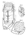
- Fig. 1 there is illustrated therein an underwater injection jacket 10 constructed and assembled in accordance with the teachings of the present invention.
- the jacket 10 is shown secured in place around a portion of an underwater concrete column 12 having cracks 13 therein which are to be sealed utilizing the method of the present invention to be described in greater detail hereinafter.
- the jacket 10 is made from a generally rectangular coilable sheet of flexible material 14 which is typically a clear or colored plastic material having a thickness of approximately 0.060 inch.
- the material from which the sheet 14 is made can be chosen from the class consisting of ABS, PVC and plexiglass. Such material is relatively stiff but still sufficiently flexible so that it can be bent or coiled.
- the sheet 14 and jacket 10 formed therewith has an upper edge 16 and a lower edge 18.
- a strip of sealing material 20 is secured to the inner marginal surface of the sheet 14 adjacent the upper edge 16 so that when the sheet 14 is coiled around the piling 12, the sealing strip 20 forms a sealing ring.
- another sealing strip 22 is secured to the inner marginal surface area of the sheet 14 adjacent the lower edge 18 so as to form a lower seal when the sheet 14 is coiled around the piling 12 to form the jacket 10.
- the jacket 10 can be provided with an elongate strip 24 which is secured to the inner marginal surface area adjacent a first mating edge 26 of the sheet 14.
- the sealing strips 20, 22 and 24 are all made of a compressible foam material such as polyethylene or ethylenevinyl acetate.
- a clamping system 30 mounted on these margins adjacent the mating edges 26 and 28 for securing the margins together with the mating edges secured in place relative to each other is a clamping system 30.
- the clamping system 30 consists of three blocks 32 which are secured to the sheet 14 and spaced a short distance from the first mating edge 26. Extending from each block 32, which is glued or otherwise adhered to the sheet 14, is a threaded rod 34. Each threaded rod 34 has a washer 36 and wing nut 38 received thereon and the distal end of the rod 34 is stripped to prevent the wing nut 38 from coming off the threaded rod 34.
- the clamping system 30 further includes a bar or angle iron 40 having an L-shaped cross section with side 42 thereof fixed to the margin adjacent the second mating edge 28 with the other side 44 thereof extending outwardly from the jacket 10 flush with the second mating edge 28. Also the side 44 has three slots 46 therein each of which is adapted to receive one of the threaded rods 34 therein so that the wing nuts 38 can be threaded on the rods 34 against the side 44 so as to draw the mating edge 28 and adjacent margin over the first mating edge 26 and adjacent margin as best shown in Fig. 3.
- the clamping system 30 permits an underwater diver to easily move the threaded rods 34 into the slots 46 for effecting clamping of the sheet 14 around a piling 12 and to provide a tight, overlapping, snug fit of the marginal areas adjacent the mating edges 26 and 28 to form the jacket 10.
- the notches 46 can be formed in an L-shape such as the L-shape shown for the notches illustrated in Fig. 11 for the bar of angle iron used in another embodiment of the jacket of the present invention.
- the sheet 14 In assembling the sheet 14 around the piling 12 to form the jacket 10, the sheet 14, which is in a generally coiled shaped'but with the mating edges 26 and 28 spaced apart, is fitted about a portion of a piling, such as the concrete piling 12 and the clamping system is brought together with the rods 34 received in the slots 46 and the wing nuts 38 threaded down to draw the marginal area adjacent the edge 28 over the edge 26 as shown with the sealing strips 20, 22 and 24 in sealing contact with the piling 12 and the jacket 10.
- a piling such as the concrete piling 12
- the jacket 10 is provided with three lower inlet ports 52 which are positioned adjacent the lower edge 18 of the jacket 10 and equally spaced around the jacket 10.
- Each port 52 includes a quick-connect female coupling member of a quick-connect coupling assembly which is of conventional type and which includes a one way check valve therein.
- the ports 52 are closed and when a male coupling member is coupled with the female coupling member forming part of each port 52 the one way check valve in each port 52 allows fluid material to be injected into the annular space 50 but prevents "outflow" or "backflow” through the port 52.
- the jacket 10 is provided with three venting ports or outlet ports 54 which are situated in the jacket adjacent the upper edge 20 and equally spaced around the jacket 10.
- Each of the venting or outlet ports 54 has a manually manipulatable valve therein with a movable valve controlling element 56 in the form of a wing.
- the outlet ports 54 can be located directly above the inlet ports 52 or, as shown in Fig. 3, the outlet ports 54 can be staggered from the inlet ports 52.
- a diver will spread the mating edges 26 and 28 of the coiled sheet 14 apart to place the jacket over a portion of a piling such as the piling 12 which is to be restored and rehabilitated. Then, the diver will place the rods 34 in the notches 46 and the wing nuts 38 are tightened down to draw the mating edge portions 26 and 28 into an overlapping position as shown in Fig. 3 thereby to securely clamp the jacket 10 in place.
- the other ends of the tubings 71 - 73 are coupled by two T connectors 76 and 78 to the outlet of a conventional resin injection gun 80.
- the injection gun 80 has a hand-manipulatable trigger 82 and is coupled by a tubing 84 to a source of epoxy resin composition which is typically located at the surface on the pier or adjacent boat.
- the sheet 14 can be of a clear plastic material or can be pigmented. If it is of clear plastic material, the diver may be able to see the flow of epoxy resin composition into the annular space 50. In this respect, the epoxy resin composition is typically a white colored material.
- the wings 56 Prior to injecting the epoxy resin composition into the annular space, the wings 56 are manipulated to open each one of the ports 54 so that as epoxy resin composition is injected into the annular space 50 it extrudes the water from the annular space and forces the water out through the ports 54.
- the epoxy resin composition utilized in restoring and rehabilitating the wood, concrete or steel piling 12 is a special epoxy resin of the type disclosed in the U.S. Patent 4 221 890 issued on September 9,1980 for: EPOXY RESIN COMPOSITION AND METHOD FOR MAKING SAME, the disclosure of which is incorporated herein by reference.
- the epoxy resin composition disclosed and claimed therein will cure at very low temperatures and at least at 0°F for a.dry substrate on which it is applied and at a temperature of at least 33°F for a wet substrate to which it is applied.
- such epoxy resin composition is a low viscosity, 100' % solids epoxy-amine compound, which is workable and cures at a temperature at least as low as 0°F and at least as high as 140°F, which is particularly adapted for concrete rehabilitation and preservation and which comprises an epoxy resin having a plurality of 1,2 epoxy groups and a curing agent including a first aliphatic polyamine composition, a first accelerator comprising Bisphenol-A, a second polyamine composition, and a second accelerator selected from a group comprising N-aminoethylpiperazine, nonyl phenol and tris (dimethylaminomethyl) phenol.
- the epoxy resin composition is injected into the annular space 50 until the operator, namely an underwater diver, notices the epoxy resin composition exiting out of the ports 54. At this time, he releases the trigger 82 and closes the valves in the ports 54 by manipulating the wings 56 forming the control element for the valves. Then, the couplings 74 are removed from the ports 52 which automatically close because of the one way check valves therein and the jacket is left in place to allow the epoxy resin to cure and seal the cracks on the surface of the piling 12.
- the wood or concrete piling 12 may have cracks extending substantially into and through the piling or other underwater structure to be rehabilitated and restored. In such circumstances, it is desirable to fill the cracks within the piling with the epoxy resin composition.
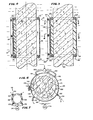
- another embodiment of the underwater injection jacket of the present invention is utilized and such underwater injection jacket is illustrated in Figs. 5, 6 and 7 and generally identified by the reference numeral 110.
- the underwater injection jacket 110 is adapted to be fitted around and secured around a wood or concrete piling such as a concrete piling 112 shown in Fig. 5 which has cracks 113 (Fig. 6) which extending through the piling 112.
- the jacket 110 is made from a sheet of flexible, clear or pigmented, plastic material such as ABS, PBC or plexiglass.
- a sealing strip 116 is secured to the inner surface of the sheet 114 adjacent the bottom edge 118 of the sheet/jacket 110 by a conventional epoxy resin composition and another sealing strip of foam material 120 is secured to the inner surface of the sheet 114 adjacent the top edge 122 of the sheet/ jacket 110 by a conventional epoxy resin composition.
- the jacket 110 also includes a first elongate sealing strip 124 which extends between the top and bottom edges 122 and 118 adjacent a first mating edge126 and adhered by a conventional epoxy resin composition to the inner marginal surface area of the sheet 114 adjacent the mating edge 126 as best shown in Fig. 6.
- the jacket 110 has a second mating edge 128 of the sheet 114 which extends over and overlaps the first mating edge 126 and the margin adjacent thereto.
- a clamping system 130 in this case a clamping system identical to the clamping system 30 shown in Fig. 1, is mounted on the marginal surface areas adjacent the edges 126 and 128 for drawing the edges together and securing them in place relative to each other as shown in Fig. 6.
- a second sealing strip 132 is secured to the inner surface of the sheet 114 at a position diametrically opposite the strip 114 and extends between the bottom edge 118 and top edge 122 of the sheet/jacket 110.
- This sealing strip 132 is secured to the sheet 114 by a conventional epoxy resin composition.
- All of the sealing strips, 116, 120, 124 and 132 are preferably made of a compressible foam material such as polyethylene or ethylenevinyl acetate. Also, the inwardly facing surfaces of these sealing strips, i.e., those surfaces which will engage the piling 112, are coated with the special epoxy resin which sets, bonds and cures to wet substrates at temperatures at least as low as 33°F prior to the installation of the jacket 110 around the piling 112.
- first and second semi-annular space portions 141 and 142 on opposite sides of the piling 112 as best shown in Fig. 6.
- the first semi-annular space portion 141 is referred to as positive pressure space 141 and the second semi-annular space portion 142 is referred to as a negative pressure space 142 for reasons which will be described in greater detail hereinafter.
- the jacket 110 is provided with four inlets ports 152 identical to the inlet port quick-connect female coupling members 52 shown in Fig. 1 located adjacent the bottom edge 118 of the sheet/ jacket 110 and four upper outlet ports 154 situated adjacent the upper edge 122 of the sheet/jacket 110.
- the outlet ports 154 each have a manually manipulatable valve associated therewith including a movable valve control element or wing 155.
- the inlet ports 152 and the outlet ports 154 are located at equidistant positions about the circumference of the jacket 110 with the outlet ports 154 located above the inlet ports 152. Also, two inlet ports 152 provide inlets to the positive pressure space 141 and the other two inlet ports 152 provide inlets and outlets to the negative pressure space 142. Likewise, two of the outlet ports 154 provide outlets from the positive pressure space 141 and the other two outlet ports 154 provide outlet ports from the negative pressure space 142.
- tubings 162 and 164 are connected to a T 168 leading to an injection gun (not shown) similar to the gun 80 shown in Fig. 1.
- These two tubings 162 and 164 have male quick-connect coupling members at the end thereof adapted to be received in and coupled to the quick-connect coupling female members forming part of the inlet ports 152 into the first semi-annular space portion/positive pressure space 141.
- This is done, of course, after the jacket 110 has been assembled about the piling 112 and the sealing members 116, 120, 124 and 132 have been adhered to the column by the special epoxy resin composition which, of course, would be allowed to set, cure and bond prior to injecting epoxy resin composition into the positive pressure space 141.
- the jacket 110 is mounted on the piling 112 one day and then the method for injecting epoxy resin composition into the semi-annular space portions 141 and 142 to encapsulate that portion of the piling 112 and also fill and bond the cracks 113 therein is performed.
- the upper outlet ports 154 are opened to allow water to be forced out of the space 141.
- tubings 171 and 172 are coupled to the inlet ports 152 to the second semi-annular space portion or negative pressure space 142. These tubings are connected to a source of vacuum 174.
- the outlet ports 154 from the second semi-annular space portion 142 are also connected by two tubings 175 and 176 respectively to the source of vacuum 174.
- the method is practiced by first injecting a special epoxy resin composition of the type described above which is capable of setting, curing and bonding at temperatures as low as 33°F into the positive pressure space 141 while at the same time drawing a vacuum on all the ports communicating with the negative pressure space 142.
- the upper outlet ports 154 coupled to the positive pressure space 141 are vented so that water can be extruded from the space 141 as epoxy resin composition is injected therein.
- Epoxy resin continues to be injected into the positive pressure space 141 while a vacuum is drawn on all the ports coupled to the negative pressure space 142 until epoxy resin composition is noticed exiting from the negative pressure space 142. This is accomplished by reason of the tubings 171, 172, 175 and 176 being made of a clear plastic material and epoxy resin composition being white in color.
- the underwater diver will then know that the tubings 171 and 172 connected to the inlet ports 152 of the negative pressure space 142 should be disconnected and then two other tubings, not shown, leading from the injection gun, not shown,.are coupled to the inlet ports 152 to the negative pressure space 142 so that epoxy resin composition can be injected into both spaces while still drawing a vacuum on the upper outlet ports 154 coupled to the negative pressure space 142.
- Epoxy resin composition continues to be injected into both spaced 141 and 142 until such epoxy resin composition is observed escaping from both of the upper outlet ports 154 communicating with the negative pressure space 142. Then, the ports 154 are closed and all the tubings connected to the ports 152 are disconnected and by reason of the one way check valves in such ports 152, they are also closed.
- the epoxy resin composition is then allowed to set, cure and bond.
- the jacket, 10 or 110 being made of an inexpensive material, is allowed to stay in place on the piling to provide even further protection to the piling.
- the piling 12 or 112 made of wood, concrete or steel, is rehabilitated and restored and cracks therein cemented to restore the structural integrity of the piling.
- a surfactant or air can be first introduced into the annular space or annular space portions to clean off the surfaces to be encapsulated and bonded.
- either air or surfactant can be passed through the annular space or annular space portions prior to performing the other steps of the methods described above.
- the preferred epoxy resin composition to be injected into the jacket 10 or 110 is of the type disclosed in the U.S. Patent 4 221 890 referred to above.
- the underwater injection jacket 210 is substantially identical to the underwater injection jackets 10 and 110 except for the manner in which the sheet 214 is secured in place around a column or piling 216 which in this embodiment has a hexogonal cross section.
- the sheet 214 has a first mating edge 226 and an adjacent margin 227 which are received under the second mating edge 228 and adjacent margin 229 as shown in Figs. 9 and 9A. Also, as best shown in Fig.
- a lower sealing strip 230 which is secured to the inner surface of the sheet 214 adjacent the lower edge 232 of the jacket 210 extends from the inner edge 226 in a counterclockwise direction around, adjacent to and secured to the inner surface of the sheet 214 to a point spaced from the second mating edge 228. In this way, the first mating edge with the sealing ring terminating*-thereat are both received under the second mating edge 228 and adjacent margin 229.
- an over- center toggle locking action type clamping system 240 is utilized. As shown in Figs. 9 and 10, the clamping system 240 includes a first elongate bar of angle iron 242 which is secured to the margin 227 at a point spaced behind the first mating edge 226. A lever arm assembly 244 comprising first and second lever arms 246 and 248 and a connecting bar 150 are pivotally connected to the bar of angle iron 242.
- a second bar of angle iron is secured to the margin 229 such that the outwardly extending portion of the bar of angle iron 252 extends flush with the second mating edge 228 as shown in Fig. 10.
- Each U-shaped rod 256 and 258 Pivotally connected to each of the lever arms 246 and 248 is a U-shaped rod 256 or 258.
- Each U-shaped rod 256 and 258 has two leg portions such as the leg portion 260 shown in Fig. 10. This leg portion has a threaded outer end 262 for holding a spring and stop assembly 264 on the leg 260.
- the stop and spring assembly includes a spring 266 which extends between a washer 268 adjacent the nut 262 and a stop member 270.
- the leg portion 260 is adapted to be received in a slot in the bar 252 such as the slot 272 shown in Fig. 11 having an inlet portion 273 and a notch retaining portion 274.
- the rod is received through the inlet portion 273 and then moved into the retaining notch portion 274.
- the stop 270 can take the form of a washer on the rod leg 260 or could take the form of a short strap which extends to the other leg of the two legs of the ⁇ U-shaped rod 256 to form a stop of the spring and stop assembly 264 mounted on that leg also.
- the slot in the bar in this case, slot 280 can have a generally U shape and the bar 252 can have an aperture 282 therein adjacent the slot 280. Then a detent 284 (Fig. 10) is punched out of the strap 270 and is adapted to be received through the aperture 282 when the U-shaped rods 256 and 258 of the clamping system 240 are moved into the slots 280 for positioning the stop 270 behind the upright portion of the bar of angle iron 252 as shown in Fig. 2.
- lever arms 246 and 248 are rotated from an outer position to an inner position adjacent the jacket 210 to cause the spring 266 and stop member 270 to bear against the upright portion of the bar of angle iron 252 to draw the second mating edge 228 over the margin 227.
- the detent 284 is received in the aperture 282 to prevent outward movement of the rods 246 from the slots 280.
- the lever arms 246 and 248 are first moved to an extended outer position and the second mating edge 228 is brought into position over the first mating edge 226 and margin 227. Then the rod legs such as leg 260 are received in the slots 272 or 280 and the stop member 270 brought into position to bear against the upright portion of the bar of angle iron 252. The rod legs 260 are either received in the retaining notch portions 274 or the detent 284 is received in the aperture 282 (Fig. 11 or Fig. 12) to ensure releasable locking of the rod legs 260 in the slots 272 or 280.
- lever arm assembly 244 is rotated inwardly toward the jacket 214 to cause the bight portion of the U-shaped rods 256 and 254 to travel through an arcuate over-center path so as to create an over-center toggle locking action when the lever arms 246 and 248 are brought flush against the outer surface of the jacket 210.
- a spring latch member 290 (Fig. 9) is hooked over the arm or bar 250 to hold the clamping system in a releasably locked position.
- the clamping system 240 and modifications thereof described above do not require the handling of any nuts or bolts which if dropped underwater could cause a problem. Yet at the same time, the clamping system 240 permits an easy and simple clamping of the mating edges 226 and 228 in overlapping relationship relative to each other and with the jacket 214 firmly clamped about the piling 216.
- the sheet of plastic material from which the jacket is made i.e. sheet 14, 114 or 214
- the sheet of plastic material from which the jacket is made can be made of other materials besides plastic.
- it has a dimension of 0.060 inch.
- such sheet can have a variety of dimensions.
- the sheet can be of any desired length with a preferred length being between 1 foot and 8 feet, such as 2 or 3 feet in length.
- additional clamping members or clamping rods can be utilized and additional inlet and outlet ports can be provided in the jacket.
- the width of the sheet 14, 114 or 214 i.e., the circumferential extent of the sheet, can be sized to accomodate the particular piling. This width or circumferential extent can be up to five feet and more.
- strips of foam material are utilized with the jackets 10, 110 and 210 for sealing the annular space 50, or 141 and 142 between the jacket 10, 110 or 210 and the piling 12, 112 or 216, other sealing or gasket materials could be utilized.
- clamping systems 30 and 240 have been described above, it is to be understood that other forms of clamping systems can be utilized provided they provide a simple mechanism for clamping the mating edges of the sheet 14, 114 or 214 without the use of detached small pieces such as nuts or bolts which could easily be dropped and lost by a diver underwater.
Landscapes
- Engineering & Computer Science (AREA)
- Structural Engineering (AREA)
- Life Sciences & Earth Sciences (AREA)
- General Life Sciences & Earth Sciences (AREA)
- Mining & Mineral Resources (AREA)
- Paleontology (AREA)
- Civil Engineering (AREA)
- General Engineering & Computer Science (AREA)
- Lining Or Joining Of Plastics Or The Like (AREA)
Applications Claiming Priority (2)
| Application Number | Priority Date | Filing Date | Title |
|---|---|---|---|
| US06/285,964 US4439070A (en) | 1981-07-23 | 1981-07-23 | Method for restoring an underwater piling and an underwater jacket used therewith |
| US285964 | 1981-07-23 |
Publications (3)
| Publication Number | Publication Date |
|---|---|
| EP0071217A2 true EP0071217A2 (de) | 1983-02-09 |
| EP0071217A3 EP0071217A3 (en) | 1983-04-27 |
| EP0071217B1 EP0071217B1 (de) | 1986-10-15 |
Family
ID=23096444
Family Applications (1)
| Application Number | Title | Priority Date | Filing Date |
|---|---|---|---|
| EP82106693A Expired EP0071217B1 (de) | 1981-07-23 | 1982-07-23 | Verfahren zum Ausbessern von Unterwasserpfählen und Unterwasserummantelung dafür |
Country Status (3)
| Country | Link |
|---|---|
| US (1) | US4439070A (de) |
| EP (1) | EP0071217B1 (de) |
| DE (1) | DE3273816D1 (de) |
Cited By (10)
| Publication number | Priority date | Publication date | Assignee | Title |
|---|---|---|---|---|
| FR2571633A1 (fr) * | 1984-08-10 | 1986-04-18 | Irete Sa | Dispositif pour le traitement anticorrosion et le renforcement mecanique d'elements constitutifs d'ouvrages immerges |
| EP0201122A1 (de) * | 1985-04-20 | 1986-11-12 | Bouwchemie Leggedoor B.V. | Verfahren zum Ausbessern oder Schützen eines Unterwasserbauwerkes und dazu benutzter Mantel |
| GB2177148A (en) * | 1985-06-28 | 1987-01-14 | Taylor Woodrow Const Ltd | Repairing concrete piles |
| WO1987003318A1 (fr) * | 1985-12-02 | 1987-06-04 | Irete S.A. | Dispositif pour la prise d'empreinte d'elements de structures immergees et procede mettant en oeuvre un tel dispositif |
| FR2609739A1 (fr) * | 1987-01-21 | 1988-07-22 | Sevene Jean Pierre | Procede pour la protection superficielle d'une construction immergee, dispositif pour la mise en oeuvre dudit procede et construction ainsi obtenue |
| FR2742779A1 (fr) * | 1995-12-26 | 1997-06-27 | Scaphocean | Procede et installation pour la protection de supports en metal, en beton ou analogues, notamment contre la corrosion |
| EP0789802A4 (de) * | 1992-02-04 | 1997-08-20 | ||
| US6033150A (en) * | 1997-02-25 | 2000-03-07 | Culen; Matthew F. | Method for suppressing borer attack of marine structures and an improved, borer-immune marine structure |
| FR2885629A1 (fr) * | 2005-05-12 | 2006-11-17 | Lefevre Sa Sa M | Procede de traitement anti-corrosion d'une structure creuse et structure creuse |
| CN102926385A (zh) * | 2012-11-21 | 2013-02-13 | 江苏省交通工程集团有限公司 | 桥梁大直径灌注桩成桩夹泥缺陷的处理方法 |
Families Citing this family (58)
| Publication number | Priority date | Publication date | Assignee | Title |
|---|---|---|---|---|
| US4862568A (en) * | 1986-04-09 | 1989-09-05 | Shell Offshore Inc. | Apparatus to drill and tap a hollow underwater member |
| US4692064A (en) * | 1986-04-09 | 1987-09-08 | Shell Offshore Inc. | Method to drill and tap a hollow underwater member |
| US4892410A (en) * | 1986-06-16 | 1990-01-09 | Sandoz Ltd. | Method and apparatus for protective encapsulation of structural members |
| US4876896A (en) * | 1986-06-16 | 1989-10-31 | I.W. Industries, Inc. | Method of testing protective encapsulation of structural members |
| US4993876A (en) * | 1986-06-16 | 1991-02-19 | 501 Sandoz, Ltd. | Method and apparatus for protective encapsulation of structural members |
| US4779389A (en) * | 1987-03-02 | 1988-10-25 | Landers Phillip G | Method and apparatus for insitu reinforcement, repair and safety enhancement of wooden poles |
| US4764054A (en) * | 1987-04-07 | 1988-08-16 | Sutton John S | Piling-jacket system and method |
| US4771530A (en) * | 1987-04-08 | 1988-09-20 | General Atomics | Application of inwardly directed prestressing pressure to concrete members |
| US4894405A (en) * | 1988-11-25 | 1990-01-16 | Tremco Incorporated | Concrete and masonry waterproofing composition |
| US5065795A (en) * | 1989-03-01 | 1991-11-19 | General Atomics | Prestressed concrete articles |
| US4936006A (en) * | 1989-03-01 | 1990-06-26 | General Atomics | Method of making prestressed concrete articles |
| US6219991B1 (en) | 1990-08-06 | 2001-04-24 | Hexcel Corporation | Method of externally strengthening concrete columns with flexible strap of reinforcing material |
| US5573354A (en) * | 1995-02-08 | 1996-11-12 | Restoration Technologies, Inc. | Timber pile repair system |
| US6189286B1 (en) | 1996-02-05 | 2001-02-20 | The Regents Of The University Of California At San Diego | Modular fiber-reinforced composite structural member |
| US6010278A (en) * | 1996-07-19 | 2000-01-04 | Shell Oil Company | Fairings for deepwater drilling risers |
| US6048136A (en) * | 1996-07-19 | 2000-04-11 | Shell Oil Company | Vortex induced vibration protection for deepwater drilling risers |
| US6223672B1 (en) | 1996-11-15 | 2001-05-01 | Shell Oil Company | Ultrashort fairings for suppressing vortex-induced-vibration |
| US6006488A (en) * | 1997-04-24 | 1999-12-28 | Nippon Steel Corporation | Supplementary reinforcing construction for a reinforced concrete pier and a method of carrying out the supplementary reinforcement for the reinforced concrete pier |
| AUPO666597A0 (en) * | 1997-05-07 | 1997-05-29 | Amog Technologies Pty Ltd | Repair of tubular structural members |
| US20030085482A1 (en) * | 1997-05-07 | 2003-05-08 | Paul Sincock | Repair of structural members |
| US5941662A (en) * | 1997-07-11 | 1999-08-24 | Riserclad International International, Inc. | Method and apparatus for protecting a flange |
| KR100380563B1 (ko) * | 1999-12-08 | 2003-04-23 | 박재만 | 수중 교각 기초 보강장치 및 보강공법 |
| US6695540B1 (en) | 2000-11-14 | 2004-02-24 | Weldon Taquino | Vortex induced vibration suppression device and method |
| US6896447B1 (en) | 2000-11-14 | 2005-05-24 | Weldon Taquino | Vortex induced vibration suppression device and method |
| KR100433991B1 (ko) * | 2002-02-15 | 2004-06-04 | 배석동 | 수중 벽체의 보수 보강 공법 |
| US6997260B1 (en) * | 2003-03-06 | 2006-02-14 | Bruce Trader | Method of repairing tubular members on oil and gas wells |
| US20050002741A1 (en) * | 2003-05-30 | 2005-01-06 | Spectrum Dock Systems, Inc. | Apparatus and method for dock support or composite piling |
| US20040240943A1 (en) * | 2003-05-30 | 2004-12-02 | Spectrum Dock Systems, Inc. | Piling Wrap |
| EP1638899A4 (de) * | 2003-06-02 | 2009-12-16 | Polymer Group Inc | Betonverstärkungsstruktur |
| US7178974B1 (en) | 2004-08-06 | 2007-02-20 | Bell Marcus O | Plural component polymer grout plant |
| US20080087097A1 (en) * | 2005-02-18 | 2008-04-17 | Sumitomo Heavy Industries, Ltd. | Strain Measuring Device And Fixing Method Of Strain Measuring |
| US7563496B2 (en) * | 2005-05-18 | 2009-07-21 | Watson William R | Composite pipe |
| EP1912769B1 (de) * | 2005-08-05 | 2011-07-20 | 3M Innovative Properties Company | Holzbehandlung |
| KR100822401B1 (ko) * | 2006-11-08 | 2008-04-16 | 주식회사 비앤비코리아 | 교각 및 강관 말뚝의 외면 보수·보강 장치 및 이에 사용되는 조성물 |
| US20080241399A1 (en) * | 2007-03-30 | 2008-10-02 | Skyline Steel, Llc. | Method of coating and coated sheet piling sections |
| US8070390B2 (en) * | 2008-04-24 | 2011-12-06 | W. J. Castle, P.E. & Associates, P.C. | Method and apparatus for repairing piles |
| US9376782B1 (en) * | 2008-09-19 | 2016-06-28 | Mohammad R. Ehsani | Repair and strengthening of piles and pipes with FRP laminates |
| US8691340B2 (en) | 2008-12-31 | 2014-04-08 | Apinee, Inc. | Preservation of wood, compositions and methods thereof |
| US8214993B1 (en) | 2009-11-11 | 2012-07-10 | Coastal Cargo Company, Inc. | Method and apparatus for removing or reinstalling riser pipes of a riser bundle |
| US8650831B2 (en) * | 2011-07-14 | 2014-02-18 | Mohammad R. Ehsani | Reconstruction methods for structural elements |
| US8690482B2 (en) * | 2011-05-03 | 2014-04-08 | Wayne Fey | Pile encapsulation system and method |
| US9878464B1 (en) | 2011-06-30 | 2018-01-30 | Apinee, Inc. | Preservation of cellulosic materials, compositions and methods thereof |
| US8882066B2 (en) * | 2011-12-05 | 2014-11-11 | Specialized Seal Design And Distribution, Inc. | Buoyant clamp for tubular members |
| US9285065B2 (en) * | 2012-11-02 | 2016-03-15 | B. Nash Williams | Pipeline reinforcement assembly and method |
| WO2015006496A1 (en) * | 2013-07-09 | 2015-01-15 | Huncovsky Jeffrey | Systems and methods for repairing utility poles |
| US20160010297A1 (en) | 2013-08-12 | 2016-01-14 | Richard Tavella | Pilaster repair device and method for repairing seawalls |
| US9903085B2 (en) * | 2015-03-11 | 2018-02-27 | 4D Tech Solutions, Inc. | Pile repair clamp |
| US10246845B2 (en) | 2015-03-11 | 2019-04-02 | 4D Tech Solutions, Inc. | Pile repair apparatus |
| US10077538B2 (en) * | 2016-02-01 | 2018-09-18 | Warstone Innovations, Llc | Axial reinforcement system for restorative shell |
| US9611666B1 (en) * | 2016-03-03 | 2017-04-04 | Osmose Utilities Services, Inc. | Utility pole repair plate systems and methods |
| US10081963B2 (en) | 2016-03-03 | 2018-09-25 | Osmose Utilities Services, Inc. | Utility pole repair plate systems and methods |
| NO343819B1 (en) * | 2017-04-07 | 2019-06-11 | Momentum Tech As | Method for vibration damping of and vibration damper assembly for semi-submerged or submerged elongated structure |
| CN109457571B (zh) * | 2018-11-16 | 2020-10-02 | 中铁二十三局集团第四工程有限公司 | 地面变形缝修补的施工方法 |
| CN110080217A (zh) * | 2019-04-24 | 2019-08-02 | 福建建华建材有限公司 | 一种管桩合缝漏浆修补方法 |
| US11946571B1 (en) * | 2020-01-16 | 2024-04-02 | Allan John Edwards, IV | Temporary pipeline protection apparatus |
| CN114808956A (zh) * | 2022-05-14 | 2022-07-29 | 浙江大学 | 一种海上风电钢管桩加固修补施工方法 |
| CN117144901A (zh) * | 2023-08-31 | 2023-12-01 | 中国华能集团清洁能源技术研究院有限公司 | 桩基础以及桩基础修复方法 |
| CN118461592B (zh) * | 2024-07-11 | 2024-11-08 | 安徽金美亚新型建材集团有限公司 | 一种预制桩桩头快速修补装置 |
Family Cites Families (15)
| Publication number | Priority date | Publication date | Assignee | Title |
|---|---|---|---|---|
| US1629246A (en) * | 1926-11-13 | 1927-05-17 | Arrington John | Clamp |
| US2412185A (en) * | 1945-06-07 | 1946-12-03 | Weber Carl | Method of encasing driven piling |
| US2482374A (en) * | 1948-06-25 | 1949-09-20 | Herman W Ruschmeyer | Clamp |
| DE1153689B (de) * | 1959-08-19 | 1963-08-29 | Wilhelm Dahmen | Verfahren zum Ausbessern von in ein Bauwerk eingebauten Gruendungspfaehlen |
| US3331211A (en) * | 1964-04-13 | 1967-07-18 | Osmose Wood Preserving Co | Pile inspection and repair cell |
| US3238581A (en) * | 1964-06-12 | 1966-03-08 | Hartwell Corp | Toggle latch construction |
| US3524231A (en) * | 1968-01-10 | 1970-08-18 | George C Wiswell Jr | Circular underwater form with lock |
| US3690110A (en) * | 1970-04-09 | 1972-09-12 | George C Wiswell Jr | Repairing or rehabilitating steel supported h-piles |
| GB1399510A (en) * | 1972-10-11 | 1975-07-02 | Balfour Beatty Co Ltd | Artificial and natural structures |
| US3890794A (en) * | 1972-12-26 | 1975-06-24 | John T Broadfoot | Method of replacing piling |
| GB1493982A (en) * | 1974-09-16 | 1977-12-07 | Balfour Beatty Ltd | Artificial or natural structures |
| GB1494072A (en) * | 1974-12-02 | 1977-12-07 | Henry E | Methods of protecting structural members |
| GB1585627A (en) * | 1975-01-15 | 1981-03-11 | Balfour Beatty Ltd | Artificial or natural structures |
| GB2028405B (en) * | 1977-12-06 | 1982-03-31 | Henry E J W | Methods of protecting structural members |
| US4306821A (en) * | 1978-06-20 | 1981-12-22 | Moore Charles D | Method and apparatus for restoring piling |
-
1981
- 1981-07-23 US US06/285,964 patent/US4439070A/en not_active Expired - Fee Related
-
1982
- 1982-07-23 DE DE8282106693T patent/DE3273816D1/de not_active Expired
- 1982-07-23 EP EP82106693A patent/EP0071217B1/de not_active Expired
Cited By (11)
| Publication number | Priority date | Publication date | Assignee | Title |
|---|---|---|---|---|
| FR2571633A1 (fr) * | 1984-08-10 | 1986-04-18 | Irete Sa | Dispositif pour le traitement anticorrosion et le renforcement mecanique d'elements constitutifs d'ouvrages immerges |
| EP0201122A1 (de) * | 1985-04-20 | 1986-11-12 | Bouwchemie Leggedoor B.V. | Verfahren zum Ausbessern oder Schützen eines Unterwasserbauwerkes und dazu benutzter Mantel |
| GB2177148A (en) * | 1985-06-28 | 1987-01-14 | Taylor Woodrow Const Ltd | Repairing concrete piles |
| WO1987003318A1 (fr) * | 1985-12-02 | 1987-06-04 | Irete S.A. | Dispositif pour la prise d'empreinte d'elements de structures immergees et procede mettant en oeuvre un tel dispositif |
| FR2609739A1 (fr) * | 1987-01-21 | 1988-07-22 | Sevene Jean Pierre | Procede pour la protection superficielle d'une construction immergee, dispositif pour la mise en oeuvre dudit procede et construction ainsi obtenue |
| EP0789802A4 (de) * | 1992-02-04 | 1997-08-20 | ||
| FR2742779A1 (fr) * | 1995-12-26 | 1997-06-27 | Scaphocean | Procede et installation pour la protection de supports en metal, en beton ou analogues, notamment contre la corrosion |
| US6033150A (en) * | 1997-02-25 | 2000-03-07 | Culen; Matthew F. | Method for suppressing borer attack of marine structures and an improved, borer-immune marine structure |
| FR2885629A1 (fr) * | 2005-05-12 | 2006-11-17 | Lefevre Sa Sa M | Procede de traitement anti-corrosion d'une structure creuse et structure creuse |
| BE1017420A5 (fr) * | 2005-05-12 | 2008-09-02 | Lefevre Sa M | Procede de traitement anti-corrosion d'une structure creuse et structure creuse. |
| CN102926385A (zh) * | 2012-11-21 | 2013-02-13 | 江苏省交通工程集团有限公司 | 桥梁大直径灌注桩成桩夹泥缺陷的处理方法 |
Also Published As
| Publication number | Publication date |
|---|---|
| EP0071217B1 (de) | 1986-10-15 |
| US4439070A (en) | 1984-03-27 |
| DE3273816D1 (en) | 1986-11-20 |
| EP0071217A3 (en) | 1983-04-27 |
Similar Documents
| Publication | Publication Date | Title |
|---|---|---|
| EP0071217B1 (de) | Verfahren zum Ausbessern von Unterwasserpfählen und Unterwasserummantelung dafür | |
| KR100258054B1 (ko) | 물속에 잠긴 파일의 처리, 수리 및 캡슐화를 위한 방법 및 장치 | |
| US5022685A (en) | Secondary containment system and method | |
| US3958607A (en) | Apparatus for sealing pipe leaks | |
| EP1700061B1 (de) | Vorrichtung und verfahren zur reparatur von rohren unter verwendung von hydrophilen dichtungen | |
| US5507536A (en) | Self sealing insert barb fitting (siblink) | |
| US4521037A (en) | Pipe coupling | |
| US10465825B2 (en) | Method of joining pipes and fittings with mechanical restraint members | |
| KR20030064276A (ko) | 유로시설 수복용 블록체 및 유로시설 수복공법 | |
| US20130307264A1 (en) | Water systems | |
| US2922664A (en) | Underwater coupling and method | |
| CA1186464A (en) | Method for restoring an underwater piling and an underwater jacket used therewith | |
| US20250102087A1 (en) | Apparatus and method for pipe repair | |
| US4326735A (en) | Mold useful in sealing leaks in pipes | |
| JP3217349B2 (ja) | 二次封じ込め装置と方法 | |
| NO860125L (no) | Begroningshindrende materiale. | |
| JPS6136840Y2 (de) | ||
| US20250180120A1 (en) | Arrangements for providing a substantially fluid-tight seal | |
| JP3003786U (ja) | 内部止水バンド | |
| EP0099898A1 (de) | Abdichtungsringe in röhren mit einem durchmesser in menschengrösse | |
| DE19861242C2 (de) | Vorrichtung zum Abdichten von Kanalschächten gegen Eindringen von Wasser oder anderen flüssigen Medien | |
| DE202025106018U1 (de) | Schalungsmanschette | |
| JPH0412120Y2 (de) | ||
| JPH03206295A (ja) | 係合部材およびそれを用いた止水シート | |
| TH33188A (th) | อุปกรณ์หลอดฉีดสำหรับข้อต่อโครงสร้างเพื่อการปิดผนึก |
Legal Events
| Date | Code | Title | Description |
|---|---|---|---|
| PUAI | Public reference made under article 153(3) epc to a published international application that has entered the european phase |
Free format text: ORIGINAL CODE: 0009012 |
|
| AK | Designated contracting states |
Designated state(s): BE DE FR GB IT NL SE |
|
| PUAL | Search report despatched |
Free format text: ORIGINAL CODE: 0009013 |
|
| AK | Designated contracting states |
Designated state(s): BE DE FR GB IT NL SE |
|
| 17P | Request for examination filed |
Effective date: 19831027 |
|
| GRAA | (expected) grant |
Free format text: ORIGINAL CODE: 0009210 |
|
| AK | Designated contracting states |
Kind code of ref document: B1 Designated state(s): BE DE FR GB IT NL SE |
|
| REF | Corresponds to: |
Ref document number: 3273816 Country of ref document: DE Date of ref document: 19861120 |
|
| ET | Fr: translation filed | ||
| ITF | It: translation for a ep patent filed | ||
| PGFP | Annual fee paid to national office [announced via postgrant information from national office to epo] |
Ref country code: NL Payment date: 19870731 Year of fee payment: 6 |
|
| PLBE | No opposition filed within time limit |
Free format text: ORIGINAL CODE: 0009261 |
|
| STAA | Information on the status of an ep patent application or granted ep patent |
Free format text: STATUS: NO OPPOSITION FILED WITHIN TIME LIMIT |
|
| 26N | No opposition filed | ||
| PG25 | Lapsed in a contracting state [announced via postgrant information from national office to epo] |
Ref country code: GB Effective date: 19890723 |
|
| PG25 | Lapsed in a contracting state [announced via postgrant information from national office to epo] |
Ref country code: SE Effective date: 19890724 |
|
| PG25 | Lapsed in a contracting state [announced via postgrant information from national office to epo] |
Ref country code: BE Effective date: 19890731 |
|
| BERE | Be: lapsed |
Owner name: DIMMICK FLOYD ELVIN Effective date: 19890731 |
|
| PG25 | Lapsed in a contracting state [announced via postgrant information from national office to epo] |
Ref country code: NL Effective date: 19900201 |
|
| GBPC | Gb: european patent ceased through non-payment of renewal fee | ||
| NLV4 | Nl: lapsed or anulled due to non-payment of the annual fee | ||
| PG25 | Lapsed in a contracting state [announced via postgrant information from national office to epo] |
Ref country code: FR Free format text: LAPSE BECAUSE OF NON-PAYMENT OF DUE FEES Effective date: 19900330 |
|
| PG25 | Lapsed in a contracting state [announced via postgrant information from national office to epo] |
Ref country code: DE Effective date: 19900403 |
|
| REG | Reference to a national code |
Ref country code: FR Ref legal event code: ST |
|
| ITTA | It: last paid annual fee | ||
| EUG | Se: european patent has lapsed |
Ref document number: 82106693.3 Effective date: 19900418 |