EP0071285B1 - Convertisseur d'énergie - Google Patents
Convertisseur d'énergie Download PDFInfo
- Publication number
- EP0071285B1 EP0071285B1 EP82200836A EP82200836A EP0071285B1 EP 0071285 B1 EP0071285 B1 EP 0071285B1 EP 82200836 A EP82200836 A EP 82200836A EP 82200836 A EP82200836 A EP 82200836A EP 0071285 B1 EP0071285 B1 EP 0071285B1
- Authority
- EP
- European Patent Office
- Prior art keywords
- thyristors
- diodes
- bridge circuit
- energy
- thyristor
- Prior art date
- Legal status (The legal status is an assumption and is not a legal conclusion. Google has not performed a legal analysis and makes no representation as to the accuracy of the status listed.)
- Expired
Links
- 238000004804 winding Methods 0.000 claims description 27
- 239000003990 capacitor Substances 0.000 description 9
- 230000007423 decrease Effects 0.000 description 5
- 230000001960 triggered effect Effects 0.000 description 4
- 238000013016 damping Methods 0.000 description 2
- 238000010586 diagram Methods 0.000 description 2
- 230000000694 effects Effects 0.000 description 2
- 230000000903 blocking effect Effects 0.000 description 1
- 238000010304 firing Methods 0.000 description 1
- 230000037431 insertion Effects 0.000 description 1
- 238000003780 insertion Methods 0.000 description 1
- 230000000717 retained effect Effects 0.000 description 1
- 229920006395 saturated elastomer Polymers 0.000 description 1
Images



Classifications
-
- H—ELECTRICITY
- H02—GENERATION; CONVERSION OR DISTRIBUTION OF ELECTRIC POWER
- H02M—APPARATUS FOR CONVERSION BETWEEN AC AND AC, BETWEEN AC AND DC, OR BETWEEN DC AND DC, AND FOR USE WITH MAINS OR SIMILAR POWER SUPPLY SYSTEMS; CONVERSION OF DC OR AC INPUT POWER INTO SURGE OUTPUT POWER; CONTROL OR REGULATION THEREOF
- H02M3/00—Conversion of DC power input into DC power output
- H02M3/22—Conversion of DC power input into DC power output with intermediate conversion into AC
- H02M3/24—Conversion of DC power input into DC power output with intermediate conversion into AC by static converters
- H02M3/28—Conversion of DC power input into DC power output with intermediate conversion into AC by static converters using discharge tubes with control electrode or semiconductor devices with control electrode to produce the intermediate AC
- H02M3/305—Conversion of DC power input into DC power output with intermediate conversion into AC by static converters using discharge tubes with control electrode or semiconductor devices with control electrode to produce the intermediate AC using devices of a thyratron or thyristor type requiring extinguishing means
- H02M3/315—Conversion of DC power input into DC power output with intermediate conversion into AC by static converters using discharge tubes with control electrode or semiconductor devices with control electrode to produce the intermediate AC using devices of a thyratron or thyristor type requiring extinguishing means using semiconductor devices only
- H02M3/3155—Conversion of DC power input into DC power output with intermediate conversion into AC by static converters using discharge tubes with control electrode or semiconductor devices with control electrode to produce the intermediate AC using devices of a thyratron or thyristor type requiring extinguishing means using semiconductor devices only with automatic control of the output voltage or current
-
- H—ELECTRICITY
- H02—GENERATION; CONVERSION OR DISTRIBUTION OF ELECTRIC POWER
- H02M—APPARATUS FOR CONVERSION BETWEEN AC AND AC, BETWEEN AC AND DC, OR BETWEEN DC AND DC, AND FOR USE WITH MAINS OR SIMILAR POWER SUPPLY SYSTEMS; CONVERSION OF DC OR AC INPUT POWER INTO SURGE OUTPUT POWER; CONTROL OR REGULATION THEREOF
- H02M7/00—Conversion of AC power input into DC power output; Conversion of DC power input into AC power output
- H02M7/42—Conversion of DC power input into AC power output without possibility of reversal
- H02M7/44—Conversion of DC power input into AC power output without possibility of reversal by static converters
- H02M7/48—Conversion of DC power input into AC power output without possibility of reversal by static converters using discharge tubes with control electrode or semiconductor devices with control electrode
- H02M7/505—Conversion of DC power input into AC power output without possibility of reversal by static converters using discharge tubes with control electrode or semiconductor devices with control electrode using devices of a thyratron or thyristor type requiring extinguishing means
- H02M7/515—Conversion of DC power input into AC power output without possibility of reversal by static converters using discharge tubes with control electrode or semiconductor devices with control electrode using devices of a thyratron or thyristor type requiring extinguishing means using semiconductor devices only
- H02M7/523—Conversion of DC power input into AC power output without possibility of reversal by static converters using discharge tubes with control electrode or semiconductor devices with control electrode using devices of a thyratron or thyristor type requiring extinguishing means using semiconductor devices only with LC-resonance circuit in the main circuit
- H02M7/5233—Conversion of DC power input into AC power output without possibility of reversal by static converters using discharge tubes with control electrode or semiconductor devices with control electrode using devices of a thyratron or thyristor type requiring extinguishing means using semiconductor devices only with LC-resonance circuit in the main circuit the commutation elements being in a push-pull arrangement
- H02M7/5236—Conversion of DC power input into AC power output without possibility of reversal by static converters using discharge tubes with control electrode or semiconductor devices with control electrode using devices of a thyratron or thyristor type requiring extinguishing means using semiconductor devices only with LC-resonance circuit in the main circuit the commutation elements being in a push-pull arrangement in a series push-pull arrangement
Definitions
- the series resonant bridge circuit is combined with a second series resonant bridge circuit.
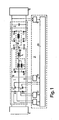
- the second bridge circuit consists of thyristor pairs 6, 26 and 7, 27, coil 28 and capacitor 29. Across thyristors 26 and 27 are diodes 30 and 31 in antiparallel connection.
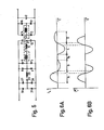
- the self-induction of coil 28 and the capacitance of capacitor 29 are so selected that the resonant frequency of the second bridge circuit is higher than that of the first bridge circuit, but is less than twice that of the first bridge circuit.
- Fig. 6A shows the flow of current i L through coil 10
- Fig. 6B the flow of current i L * through coil 28.
- Thyristor 32 is triggered at the same time as thyristors 6A and 7B and at the same time diodes 8B and 9A start conducting.
- Thyristor 33 is triggered at the same time as thyristors 6B and 7A and at the same time diodes 8A and 9B start conducting.
- thyristor 32 will be triggered at the start of phase A, thyristor 33 at the start of both phases B and C, and thyristor 32 again at the start of phase D.
- the trigger pulse supplied from control unit 20 to thyristor 32 must in any case be of longer duration than the period required for extinguishing thyristor 33; conversely, the trigger pulse supplied from control unit 20 to thyristor 33 must be of longer duration than the period required for extinguishing thyristor 32. Because of the current flow in the series resonant circuit during dwell time T R it may occur that thyristor 33 is not extinguished by the end of phase B or thyristor 32 by the end of phase D. To prevent such a situation, various measures may be taken. A feasible measure is the insertion of an LC network consisting of coil 34 and capacitor 35 across the output transformer 13 in the bridge circuit.
- the series resonant bridge circuit consists of a full bridge configuration.
- the measure taken consists in including an additional winding 36 to the output transformer 13, a rectifier circuit constituted by diodes 37 and 38, two FET switches 39 and 40 and an RC network constituted by capacitor 41 and load resistance 42.
- the capacitor 41 charged during the preceding thyristor and diode phases, discharges and causes in the bridge circuit a voltage which extinguishes the last conducting thyristor of thyristors 32 and 33.
- the FET switches are controlled from control unit 20.
- the control unit 20 delivers the trigger pulse for the particular FET switch; the duration of this trigger pulse is in any case such that the relevant thyristor is extinguished within this period.
Landscapes
- Engineering & Computer Science (AREA)
- Power Engineering (AREA)
- Ac-Ac Conversion (AREA)
Claims (5)
Applications Claiming Priority (2)
| Application Number | Priority Date | Filing Date | Title |
|---|---|---|---|
| NL8103474 | 1981-07-23 | ||
| NL8103474A NL8103474A (nl) | 1981-07-23 | 1981-07-23 | Energieomzetter. |
Publications (2)
| Publication Number | Publication Date |
|---|---|
| EP0071285A1 EP0071285A1 (fr) | 1983-02-09 |
| EP0071285B1 true EP0071285B1 (fr) | 1985-10-23 |
Family
ID=19837834
Family Applications (1)
| Application Number | Title | Priority Date | Filing Date |
|---|---|---|---|
| EP82200836A Expired EP0071285B1 (fr) | 1981-07-23 | 1982-07-05 | Convertisseur d'énergie |
Country Status (4)
| Country | Link |
|---|---|
| US (1) | US4488213A (fr) |
| EP (1) | EP0071285B1 (fr) |
| DE (1) | DE3267011D1 (fr) |
| NL (1) | NL8103474A (fr) |
Cited By (1)
| Publication number | Priority date | Publication date | Assignee | Title |
|---|---|---|---|---|
| KR100882383B1 (ko) * | 2001-06-28 | 2009-02-05 | 폴리머리 유로파 에스.피.에이. | 티타늄 함유 제올라이트 촉매의 활성화 방법 및산화반응에서의 용도 |
Families Citing this family (12)
| Publication number | Priority date | Publication date | Assignee | Title |
|---|---|---|---|---|
| DE3246057A1 (de) * | 1982-12-13 | 1984-06-14 | Metallgesellschaft Ag, 6000 Frankfurt | Einrichtung zur spannungsversorgung eines elektrofilters |
| JPH0720379B2 (ja) * | 1984-06-04 | 1995-03-06 | 閃一 増田 | 高周波高圧電源 |
| DD236213A1 (de) * | 1985-04-11 | 1986-05-28 | Transform Roentgen Matern Veb | Selbstloeschender wechselrichter |
| NL8601798A (nl) * | 1986-07-10 | 1988-02-01 | Hollandse Signaalapparaten Bv | Energieomzetter. |
| US4873408A (en) * | 1987-12-28 | 1989-10-10 | General Electric Company | Magnetron with microprocessor based feedback control |
| CA1318349C (fr) * | 1988-03-11 | 1993-05-25 | Yoshio Suzuki | Convertisseur de courant pour circuit resonnant serie et methode de controle connexe |
| DE4009020A1 (de) * | 1990-03-21 | 1991-09-26 | Philips Patentverwaltung | Serienresonanz-wechselrichter, insbesondere fuer einen roentgengenerator |
| EP0469173A1 (fr) * | 1990-08-02 | 1992-02-05 | Asea Brown Boveri Ag | Inverseur protégé contre le courant excessif |
| DE4405239B4 (de) * | 1994-02-18 | 2006-12-14 | Sms Elotherm Gmbh | Verfahren und Vorrichtung zum Schutz von abschaltbaren Leistungshalbleitern eines Schwingkreisumrichters vor harten Schaltvorgängen |
| US8104959B2 (en) * | 2003-09-09 | 2012-01-31 | Cargill, Incorporated | Multi-handled sealed bag |
| PL217714B1 (pl) * | 2008-06-20 | 2014-08-29 | Akademia Górniczo Hutnicza Im Stanisława Staszica | Wielorezonansowy zasilacz z integralnym ogranicznikiem dobroci |
| DE102012220376A1 (de) * | 2012-11-08 | 2014-05-08 | Robert Bosch Gmbh | Vorrichtung und Verfahren zum Laden eines elektrischen Energiespeichers aus einer Wechselspannungsquelle |
Family Cites Families (7)
| Publication number | Priority date | Publication date | Assignee | Title |
|---|---|---|---|---|
| US3483462A (en) * | 1967-09-29 | 1969-12-09 | Gen Electric | Inverters operable with a wide range of load impedances |
| US3852656A (en) * | 1974-04-19 | 1974-12-03 | Gen Motors Corp | Inverter fault protection and frequency limiting circuit |
| US3953779A (en) * | 1974-05-30 | 1976-04-27 | Francisc Carol Schwarz | Electronic control system for efficient transfer of power through resonant circuits |
| US4200830A (en) * | 1977-08-10 | 1980-04-29 | Esb Incorporated | Series resonant battery charger and control therefor |
| DE2746115A1 (de) * | 1977-10-13 | 1979-04-19 | Siemens Ag | Wechselrichter mit mindestens zwei steuerbaren lastthyristoren |
| DE2836573C3 (de) * | 1978-08-21 | 1981-07-09 | Siemens Ag, 1000 Berlin Und 8000 Muenchen | Steuersatz für einen mehrphasigen Stromrichter |
| JPS5840916B2 (ja) * | 1978-11-13 | 1983-09-08 | 日本電信電話株式会社 | 自然転流形dc↓−dcコンバ−タ |
-
1981
- 1981-07-23 NL NL8103474A patent/NL8103474A/nl not_active Application Discontinuation
-
1982
- 1982-07-05 EP EP82200836A patent/EP0071285B1/fr not_active Expired
- 1982-07-05 DE DE8282200836T patent/DE3267011D1/de not_active Expired
- 1982-07-14 US US06/398,174 patent/US4488213A/en not_active Expired - Lifetime
Cited By (1)
| Publication number | Priority date | Publication date | Assignee | Title |
|---|---|---|---|---|
| KR100882383B1 (ko) * | 2001-06-28 | 2009-02-05 | 폴리머리 유로파 에스.피.에이. | 티타늄 함유 제올라이트 촉매의 활성화 방법 및산화반응에서의 용도 |
Also Published As
| Publication number | Publication date |
|---|---|
| DE3267011D1 (en) | 1985-11-28 |
| US4488213A (en) | 1984-12-11 |
| NL8103474A (nl) | 1983-02-16 |
| EP0071285A1 (fr) | 1983-02-09 |
Similar Documents
| Publication | Publication Date | Title |
|---|---|---|
| US5930122A (en) | Inverter and DC power supply apparatus with inverter used therein | |
| US3953779A (en) | Electronic control system for efficient transfer of power through resonant circuits | |
| US3120633A (en) | Series inverter circuit having controlled rectifiers with power diodes in reverse parallel connection | |
| US4488213A (en) | Energy converter | |
| US5121317A (en) | Inverter device | |
| US5347443A (en) | Inverter apparatus and a restarting method at an instantaneous power failure | |
| GB1569836A (en) | Inverter circuits | |
| EP0391617B1 (fr) | Méthode et réseau pour modifier le facteur de puissance d'un circuit de commutation non connecté | |
| KR0134952B1 (ko) | 병렬 스위칭모드 전원공급장치의 위상차 동기 제어회로 | |
| US4495555A (en) | Energy converter | |
| EP0029067B1 (fr) | Circuit convertisseur pour stockage d'une quantité prédéterminée d'énergie | |
| US3848176A (en) | Control circuit for an inverter with a variable output voltage and frequency | |
| EP0253432B1 (fr) | Convertisseur d'énergie | |
| US4259630A (en) | AC Motor controller | |
| US4607324A (en) | Reduced harmonic current rectifier including sequentially switched secondary windings | |
| US4700372A (en) | X-ray generating apparatus | |
| JPH09289979A (ja) | 磁気共鳴イメージング装置用電源装置 | |
| US3691449A (en) | Static inverter having automatic means for providing a highly regulated a.c. output despite changes in the input d.c. level | |
| US3683263A (en) | Oscillating circuit converter | |
| EP0307057A1 (fr) | Convertisseur d'énergie | |
| JP2600814B2 (ja) | 出力トランスの偏磁防止装置 | |
| US3377543A (en) | High power converter | |
| SU961068A1 (ru) | Преобразователь напр жени | |
| JP2913683B2 (ja) | 周波数同調回路 | |
| RU2006154C1 (ru) | Преобразователь постоянного напряжения в постоянное |
Legal Events
| Date | Code | Title | Description |
|---|---|---|---|
| PUAI | Public reference made under article 153(3) epc to a published international application that has entered the european phase |
Free format text: ORIGINAL CODE: 0009012 |
|
| AK | Designated contracting states |
Designated state(s): CH DE FR GB LI NL SE |
|
| 17P | Request for examination filed |
Effective date: 19830622 |
|
| GRAA | (expected) grant |
Free format text: ORIGINAL CODE: 0009210 |
|
| AK | Designated contracting states |
Designated state(s): CH DE FR GB LI NL SE |
|
| REF | Corresponds to: |
Ref document number: 3267011 Country of ref document: DE Date of ref document: 19851128 |
|
| ET | Fr: translation filed | ||
| PLBE | No opposition filed within time limit |
Free format text: ORIGINAL CODE: 0009261 |
|
| STAA | Information on the status of an ep patent application or granted ep patent |
Free format text: STATUS: NO OPPOSITION FILED WITHIN TIME LIMIT |
|
| 26N | No opposition filed | ||
| REG | Reference to a national code |
Ref country code: GB Ref legal event code: 732 |
|
| REG | Reference to a national code |
Ref country code: FR Ref legal event code: TP Ref country code: FR Ref legal event code: CD Ref country code: FR Ref legal event code: CA |
|
| REG | Reference to a national code |
Ref country code: CH Ref legal event code: PUE Owner name: HOLLANDSE SIGNAALAPPARATEN B.V. Ref country code: CH Ref legal event code: PFA Free format text: HASRODE B.V. |
|
| NLT1 | Nl: modifications of names registered in virtue of documents presented to the patent office pursuant to art. 16 a, paragraph 1 |
Owner name: HASRODE B.V. TE EINDHOVEN. |
|
| NLS | Nl: assignments of ep-patents |
Owner name: HOLLANDSE SIGNAALAPPARATEN B.V. TE HENGELO (O.). |
|
| EAL | Se: european patent in force in sweden |
Ref document number: 82200836.3 |
|
| PGFP | Annual fee paid to national office [announced via postgrant information from national office to epo] |
Ref country code: SE Payment date: 19970610 Year of fee payment: 16 |
|
| PGFP | Annual fee paid to national office [announced via postgrant information from national office to epo] |
Ref country code: CH Payment date: 19970617 Year of fee payment: 16 |
|
| PGFP | Annual fee paid to national office [announced via postgrant information from national office to epo] |
Ref country code: FR Payment date: 19970620 Year of fee payment: 16 |
|
| PGFP | Annual fee paid to national office [announced via postgrant information from national office to epo] |
Ref country code: GB Payment date: 19970626 Year of fee payment: 16 |
|
| PGFP | Annual fee paid to national office [announced via postgrant information from national office to epo] |
Ref country code: NL Payment date: 19970717 Year of fee payment: 16 |
|
| PGFP | Annual fee paid to national office [announced via postgrant information from national office to epo] |
Ref country code: DE Payment date: 19970718 Year of fee payment: 16 |
|
| PG25 | Lapsed in a contracting state [announced via postgrant information from national office to epo] |
Ref country code: GB Free format text: LAPSE BECAUSE OF NON-PAYMENT OF DUE FEES Effective date: 19980705 |
|
| PG25 | Lapsed in a contracting state [announced via postgrant information from national office to epo] |
Ref country code: SE Free format text: LAPSE BECAUSE OF NON-PAYMENT OF DUE FEES Effective date: 19980706 |
|
| PG25 | Lapsed in a contracting state [announced via postgrant information from national office to epo] |
Ref country code: LI Free format text: LAPSE BECAUSE OF NON-PAYMENT OF DUE FEES Effective date: 19980731 Ref country code: CH Free format text: LAPSE BECAUSE OF NON-PAYMENT OF DUE FEES Effective date: 19980731 |
|
| PG25 | Lapsed in a contracting state [announced via postgrant information from national office to epo] |
Ref country code: NL Free format text: LAPSE BECAUSE OF NON-PAYMENT OF DUE FEES Effective date: 19990201 |
|
| GBPC | Gb: european patent ceased through non-payment of renewal fee |
Effective date: 19980705 |
|
| REG | Reference to a national code |
Ref country code: CH Ref legal event code: PL |
|
| EUG | Se: european patent has lapsed |
Ref document number: 82200836.3 |
|
| PG25 | Lapsed in a contracting state [announced via postgrant information from national office to epo] |
Ref country code: FR Free format text: LAPSE BECAUSE OF NON-PAYMENT OF DUE FEES Effective date: 19990331 |
|
| NLV4 | Nl: lapsed or anulled due to non-payment of the annual fee |
Effective date: 19990201 |
|
| PG25 | Lapsed in a contracting state [announced via postgrant information from national office to epo] |
Ref country code: DE Free format text: LAPSE BECAUSE OF NON-PAYMENT OF DUE FEES Effective date: 19990501 |
|
| REG | Reference to a national code |
Ref country code: FR Ref legal event code: ST |