EP0071292A1 - Câble de prétension pour structures de béton - Google Patents
Câble de prétension pour structures de béton Download PDFInfo
- Publication number
- EP0071292A1 EP0071292A1 EP82200892A EP82200892A EP0071292A1 EP 0071292 A1 EP0071292 A1 EP 0071292A1 EP 82200892 A EP82200892 A EP 82200892A EP 82200892 A EP82200892 A EP 82200892A EP 0071292 A1 EP0071292 A1 EP 0071292A1
- Authority
- EP
- European Patent Office
- Prior art keywords
- strand
- prestressing
- core wire
- modulus
- outer wires
- Prior art date
- Legal status (The legal status is an assumption and is not a legal conclusion. Google has not performed a legal analysis and makes no representation as to the accuracy of the status listed.)
- Granted
Links
- 239000004567 concrete Substances 0.000 title claims abstract description 13
- 230000003014 reinforcing effect Effects 0.000 claims description 3
- 238000012360 testing method Methods 0.000 description 12
- 239000000463 material Substances 0.000 description 7
- 238000010276 construction Methods 0.000 description 6
- 238000004364 calculation method Methods 0.000 description 5
- 238000004519 manufacturing process Methods 0.000 description 3
- 238000004873 anchoring Methods 0.000 description 2
- 238000000034 method Methods 0.000 description 2
- 239000011513 prestressed concrete Substances 0.000 description 2
- 229910000831 Steel Inorganic materials 0.000 description 1
- 230000001419 dependent effect Effects 0.000 description 1
- 230000000694 effects Effects 0.000 description 1
- 238000004836 empirical method Methods 0.000 description 1
- 238000005516 engineering process Methods 0.000 description 1
- 238000011835 investigation Methods 0.000 description 1
- 238000005259 measurement Methods 0.000 description 1
- 239000010959 steel Substances 0.000 description 1
- 230000009897 systematic effect Effects 0.000 description 1
- 238000012546 transfer Methods 0.000 description 1
Images


Classifications
-
- D—TEXTILES; PAPER
- D07—ROPES; CABLES OTHER THAN ELECTRIC
- D07B—ROPES OR CABLES IN GENERAL
- D07B1/00—Constructional features of ropes or cables
- D07B1/06—Ropes or cables built-up from metal wires, e.g. of section wires around a hemp core
- D07B1/0693—Ropes or cables built-up from metal wires, e.g. of section wires around a hemp core having a strand configuration
-
- E—FIXED CONSTRUCTIONS
- E04—BUILDING
- E04C—STRUCTURAL ELEMENTS; BUILDING MATERIALS
- E04C5/00—Reinforcing elements, e.g. for concrete; Auxiliary elements therefor
- E04C5/08—Members specially adapted to be used in prestressed constructions
-
- D—TEXTILES; PAPER
- D07—ROPES; CABLES OTHER THAN ELECTRIC
- D07B—ROPES OR CABLES IN GENERAL
- D07B2201/00—Ropes or cables
- D07B2201/20—Rope or cable components
- D07B2201/2015—Strands
- D07B2201/2024—Strands twisted
- D07B2201/2025—Strands twisted characterised by a value or range of the pitch parameter given
-
- D—TEXTILES; PAPER
- D07—ROPES; CABLES OTHER THAN ELECTRIC
- D07B—ROPES OR CABLES IN GENERAL
- D07B2501/00—Application field
- D07B2501/20—Application field related to ropes or cables
- D07B2501/2015—Construction industries
- D07B2501/2023—Concrete enforcements
Definitions
- the invention relates to prestressing strand for concrete structures comprising at least one central core wire and outer wires helically enveloping the core wire.
- Such strands are often used as reinforcing elements in pre-stressed concrete structures, in which they offer the possibility of being inserted in curved channels in the concrete structure.
- the channels are formed by enveloping tubes of steel or another material, which are pre-cast into the concrete structure.
- a commonly used type of prestressing strand comprises six equally thick outer wires and one single core wire the diameter of which is between 2 and 5 per cent greater than that of the outer wires. This last feature is of importance in order to obtain a construction of strand with a good coherence in which the outer wires fit against the core wire.
- the strand form as described above is the one most used for prestressing strands, the invention is not restricted to this specific strand construction, but it also relates to other strand constructions of the type indicated at the outset.
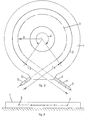
- a prestressing strand having a single core wire and six outer wires is illustrated in longitudinal view and in cross section respectively.
- Fig. 1 also there is indicated the pitch of the helices in which each of the outer wires lies.
- this pitch S is referred to by the expression "stroke length".
- Fig. 2 it is indicated that by the diameter of the strand is understood the greatest cross-sectional dimension D. It is usual to express the stroke length as a multiple of the diameter.
- the stroke length S mostly varies between 12 and 18 times the diameter.
- the limits between which the stroke length can be chosen are often derived from concepts which are developed in relation to the use of hoisting cables.
- the invention is based on the concept that for prestressing strands investigations have not yet been carried out in order to find the most suitable strand construction in practice.
- the tension condition and the deformation condition of a prestressing strand in a curved configuration, in which the strand is subjected to transverse forces and frictional forces, is highly complex, and is dependent on a great number of factors which are related to the properties of the material and the production methods for the strand.
- the modulus of deformation in the use of prestressing strand in curved channels, is very sensitive to the stroke length of the strand. More particularly, the invention consists in that a considerably better consistency between the modulus of deformation and the modulus of elasticity is obtained when the stroke lengths of the prestressing strand is chosen between 20 and 150 times the greatest diameter of the cable. It is remarkable that these limits are considerably higher than those which hitherto have been used in the art. It must be assumed that, with the greater stroke length the core wire can be more completely tensioned over its whole length and can cooperate as a load bearing element.
- the prestressing strand must sufficiently remain a unit in order that.slip occurring between the core wire and the outer wires is prevented, since this slip has a result that the core wire is no longer fully under load.
- the rate at which slipless transfer of tension between strand and the wedge anchors is possible is given by the expression "grip efficiency". It has been found that both as to the modulus of deformation and as to the grip efficiency, strands within the limits given above for the stroke length of between 20 and 150 D are considerably more satisfactory than known reinforcing strands. It has been found, in this connection, that no slip occurs between the core wire and the outer wires.
- the prestressing strand is of the type there are described above, in which/six equally thick outer wires and a single core wire with a diameter 2 to 5 percent greater than that of the outer wires, it has been found that especially good results are obtained by choosing a stroke length of 20 to 100 times the diameter of the strand. Particularly preferred is a stroke length of between 22 and 50 times the cable diameter.
- reference numeral 1 indicates a concrete plate with a thickness of 22 cm.
- the length of the curved channel part L2 is consequently 507 cm.
- a support beam 2 is located, withat the left hand side a wedge anchoring 5 for a strand and at the right hand side a similar wedge anchoring 5 behind a hydraulic press 4.
- the tensioned strand then consists of a straight piece Ll of a length of 175 cm, a curved piece of a length of L 2 of 507 cm and another straight piece of length L3 of 210 cm.
- the tests were carried out with the most common prestressing strand of thickness D of 0.5 inches.
- the strand was considered to be divided in elements, and for each element the stress and strain conditions were calculated with the application of a frictional force between the channel wall and the prestressing strand.
- the stress and strain conditions were calculated with the application of a frictional force between the channel wall and the prestressing strand.
- these friction coefficients were introduced into the calculation so that it was possible to determine by calculation, what tension forces should be present in the strand, on the basis of the total measured extension of the strand between the anchors 5. This value was compared with the actual tension forces obtained, from of which a value could be obtained for the modulus/deformation in each test performed.
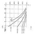
- Fig. 5 The values thus found by measurement and calculation for the modulus of deformation are set out in Fig. 5.
- the stroke length 5 is set out on the horizontal axis, expressed in mm and also as a multiple of the cable diameter D.
- the diameter D was measured separately.
- the modulus of deformation is set out, expressed in kN/mm 2 .
- a horizontal line shows the level of 201 kN/mm2, which represents the value of the modulus of elasticity E of the wire material used.
- the tests were performed with strands having stroke lengths of respectively 210, 290, 470 and 550 mm. The measured points were connected by straight lines to one another although of course a continuous line would result if more tests were performed with more varying values of the stroke length.
- the hatched area shows the area in which known strands are found. It is clear that the modulus of deformation for greater stroke length is considerably greater than for the known stroke lengths.
- the factor K (and thus also the modulus of deformation), for strands with a small stroke length diminishes when the curvature of the channel through which the strand is inserted increases. Also, it is clear from this figure that this relationship to the curvature is much less sensitive if the stroke length is increased. For values of the stroke length of 400 to 500 mm (32 to 40 D), the factor K is hardly influenced by the shape of the channel, which means that when the strand is tensioned the elongation imposed on the strand is a reliable measure for the tension which can be expected in the concrete structure.
Landscapes
- Engineering & Computer Science (AREA)
- Architecture (AREA)
- Civil Engineering (AREA)
- Structural Engineering (AREA)
- Reinforcement Elements For Buildings (AREA)
- Curing Cements, Concrete, And Artificial Stone (AREA)
Priority Applications (1)
| Application Number | Priority Date | Filing Date | Title |
|---|---|---|---|
| AT82200892T ATE13324T1 (de) | 1981-07-25 | 1982-07-14 | Vorspannseile fuer betonkonstruktionen. |
Applications Claiming Priority (4)
| Application Number | Priority Date | Filing Date | Title |
|---|---|---|---|
| CH4823/81 | 1981-07-25 | ||
| CH482381 | 1981-07-25 | ||
| NL8200195 | 1982-01-20 | ||
| NL8200195A NL180449C (nl) | 1982-01-20 | 1982-01-20 | Voorspanstreng voor betonconstructies. |
Publications (2)
| Publication Number | Publication Date |
|---|---|
| EP0071292A1 true EP0071292A1 (fr) | 1983-02-09 |
| EP0071292B1 EP0071292B1 (fr) | 1985-05-15 |
Family
ID=25696352
Family Applications (1)
| Application Number | Title | Priority Date | Filing Date |
|---|---|---|---|
| EP82200892A Expired EP0071292B1 (fr) | 1981-07-25 | 1982-07-14 | Câble de prétension pour structures de béton |
Country Status (4)
| Country | Link |
|---|---|
| EP (1) | EP0071292B1 (fr) |
| DE (1) | DE3263527D1 (fr) |
| ES (1) | ES275168U (fr) |
| NO (1) | NO157985C (fr) |
Cited By (1)
| Publication number | Priority date | Publication date | Assignee | Title |
|---|---|---|---|---|
| EP0149336A3 (en) * | 1983-12-20 | 1987-02-04 | Bridon Plc | Flexible tension members |
Families Citing this family (1)
| Publication number | Priority date | Publication date | Assignee | Title |
|---|---|---|---|---|
| ES2206037B2 (es) * | 2002-09-23 | 2005-04-01 | Nork 2, S.L. | Cable para aparatos elevadores. |
Citations (5)
| Publication number | Priority date | Publication date | Assignee | Title |
|---|---|---|---|---|
| DE483351C (de) * | 1926-07-27 | 1929-10-01 | Felten & Guilleaume Carlswerk | Verfahren zur Herstellung von Tragkoerpern fuer Haengebruecken aus schweren Tragseilen groesserer Abmessungen |
| US1822189A (en) * | 1929-05-01 | 1931-09-08 | Felten & Guilleaume Carlswerk | Method of reducing the extension of wire ropes |
| CH170415A (de) * | 1933-09-14 | 1934-07-15 | Salvisberg Theodor | Torsionsfreies Litzenseil. |
| BE824403A (fr) * | 1973-05-17 | 1975-05-02 | Cordon d'acier a profilage helicoidal | |
| GB1424672A (en) * | 1972-04-25 | 1976-02-11 | Gkn Somerset Wire Ltd | Wire strand |
-
1982
- 1982-07-14 DE DE8282200892T patent/DE3263527D1/de not_active Expired
- 1982-07-14 EP EP82200892A patent/EP0071292B1/fr not_active Expired
- 1982-07-23 ES ES1982275168U patent/ES275168U/es active Pending
- 1982-07-23 NO NO822545A patent/NO157985C/no unknown
Patent Citations (5)
| Publication number | Priority date | Publication date | Assignee | Title |
|---|---|---|---|---|
| DE483351C (de) * | 1926-07-27 | 1929-10-01 | Felten & Guilleaume Carlswerk | Verfahren zur Herstellung von Tragkoerpern fuer Haengebruecken aus schweren Tragseilen groesserer Abmessungen |
| US1822189A (en) * | 1929-05-01 | 1931-09-08 | Felten & Guilleaume Carlswerk | Method of reducing the extension of wire ropes |
| CH170415A (de) * | 1933-09-14 | 1934-07-15 | Salvisberg Theodor | Torsionsfreies Litzenseil. |
| GB1424672A (en) * | 1972-04-25 | 1976-02-11 | Gkn Somerset Wire Ltd | Wire strand |
| BE824403A (fr) * | 1973-05-17 | 1975-05-02 | Cordon d'acier a profilage helicoidal |
Cited By (2)
| Publication number | Priority date | Publication date | Assignee | Title |
|---|---|---|---|---|
| EP0149336A3 (en) * | 1983-12-20 | 1987-02-04 | Bridon Plc | Flexible tension members |
| US4813221A (en) * | 1983-12-20 | 1989-03-21 | Bridin Plc. | Flexible tension members |
Also Published As
| Publication number | Publication date |
|---|---|
| DE3263527D1 (en) | 1985-06-20 |
| NO822545L (no) | 1983-01-26 |
| ES275168U (es) | 1984-03-01 |
| NO157985B (no) | 1988-03-14 |
| NO157985C (no) | 1988-06-22 |
| EP0071292B1 (fr) | 1985-05-15 |
Similar Documents
| Publication | Publication Date | Title |
|---|---|---|
| EP2440718B1 (fr) | Structure en béton avec des fibres à fort allongement et bon ancrage | |
| US4505081A (en) | Curved device for connection between two rectilinear portions of a stretched cable | |
| US8962150B2 (en) | Steel fibre for reinforcing concrete or mortar having an anchorage end with at least two bent sections | |
| JP5819818B2 (ja) | 高伸長繊維 | |
| Utting et al. | Tensile testing of a wire rope strand | |
| CN112627540A (zh) | 大型洁净电子厂房预应力华夫板的建造方法 | |
| EP0071292B1 (fr) | Câble de prétension pour structures de béton | |
| WO2011071410A1 (fr) | Câble de renfort | |
| US4171176A (en) | Flexible bar reinforced concrete pile and method of construction | |
| JPH11323823A (ja) | 建設構造物用の吊り下げ装置 | |
| US4037979A (en) | Anchoring arrangement, especially for pre-stressed concrete constructions | |
| US3045305A (en) | Concrete prestressing cable grip | |
| US3114987A (en) | Cables for prestressing concrete | |
| US5197157A (en) | Cable-stayed bridges and more particularly to their pylons and stay cables | |
| US3696573A (en) | Pressure container prestressed concrete or the like | |
| DE69516238T2 (de) | Stahlseil zur Verstärkung elastomerer Erzeugnisse | |
| GB2177433A (en) | Anchorage for stressed reinforcing tendon | |
| RU2372458C2 (ru) | Арматурный пучок предварительно напряженного железобетонного сооружения | |
| Priestley et al. | Moment-curvature relationships for prestressed concrete in constant-moment zones | |
| EP0078564A2 (fr) | Câble de précontrainte pour structures de béton et structures de béton comprenant un tel câble | |
| US2916910A (en) | Steel reinforcement for reinforced concrete structures | |
| CN110863421A (zh) | 大型油气管道跨越锚碇预应力体系集成防护系统及工艺 | |
| JP2873343B2 (ja) | スチールコード | |
| GB2197360A (en) | Prestressed concrete articles | |
| Wheeler et al. | Effect of concrete tensile zones on the anchorage of bar reinforcement |
Legal Events
| Date | Code | Title | Description |
|---|---|---|---|
| PUAI | Public reference made under article 153(3) epc to a published international application that has entered the european phase |
Free format text: ORIGINAL CODE: 0009012 |
|
| 17P | Request for examination filed |
Effective date: 19820714 |
|
| AK | Designated contracting states |
Designated state(s): AT BE CH DE FR GB LI SE |
|
| GRAA | (expected) grant |
Free format text: ORIGINAL CODE: 0009210 |
|
| AK | Designated contracting states |
Designated state(s): AT BE CH DE FR GB LI SE |
|
| REF | Corresponds to: |
Ref document number: 13324 Country of ref document: AT Date of ref document: 19850615 Kind code of ref document: T |
|
| REF | Corresponds to: |
Ref document number: 3263527 Country of ref document: DE Date of ref document: 19850620 |
|
| ET | Fr: translation filed | ||
| PLBE | No opposition filed within time limit |
Free format text: ORIGINAL CODE: 0009261 |
|
| STAA | Information on the status of an ep patent application or granted ep patent |
Free format text: STATUS: NO OPPOSITION FILED WITHIN TIME LIMIT |
|
| 26N | No opposition filed | ||
| PGFP | Annual fee paid to national office [announced via postgrant information from national office to epo] |
Ref country code: AT Payment date: 19860609 Year of fee payment: 5 |
|
| PG25 | Lapsed in a contracting state [announced via postgrant information from national office to epo] |
Ref country code: GB Effective date: 19890714 Ref country code: AT Effective date: 19890714 |
|
| PG25 | Lapsed in a contracting state [announced via postgrant information from national office to epo] |
Ref country code: SE Effective date: 19890715 |
|
| PG25 | Lapsed in a contracting state [announced via postgrant information from national office to epo] |
Ref country code: LI Effective date: 19890731 Ref country code: CH Effective date: 19890731 Ref country code: BE Effective date: 19890731 |
|
| BERE | Be: lapsed |
Owner name: ESTEL NEDERLANDSE DRAADINDUSTRIE B.V. Effective date: 19890731 |
|
| PG25 | Lapsed in a contracting state [announced via postgrant information from national office to epo] |
Ref country code: FR Free format text: LAPSE BECAUSE OF NON-PAYMENT OF DUE FEES Effective date: 19900330 |
|
| REG | Reference to a national code |
Ref country code: CH Ref legal event code: PL |
|
| PG25 | Lapsed in a contracting state [announced via postgrant information from national office to epo] |
Ref country code: DE Effective date: 19900403 |
|
| GBPC | Gb: european patent ceased through non-payment of renewal fee | ||
| REG | Reference to a national code |
Ref country code: FR Ref legal event code: ST |
|
| EUG | Se: european patent has lapsed |
Ref document number: 82200892.6 Effective date: 19900418 |