EP0071394A2 - Maschine zum Auftragen eines Klebstoffstreifens auf den Boden eines Leistens - Google Patents
Maschine zum Auftragen eines Klebstoffstreifens auf den Boden eines Leistens Download PDFInfo
- Publication number
- EP0071394A2 EP0071394A2 EP82303817A EP82303817A EP0071394A2 EP 0071394 A2 EP0071394 A2 EP 0071394A2 EP 82303817 A EP82303817 A EP 82303817A EP 82303817 A EP82303817 A EP 82303817A EP 0071394 A2 EP0071394 A2 EP 0071394A2
- Authority
- EP
- European Patent Office
- Prior art keywords
- last
- adhesive applying
- toe end
- applying member
- adhesive
- Prior art date
- Legal status (The legal status is an assumption and is not a legal conclusion. Google has not performed a legal analysis and makes no representation as to the accuracy of the status listed.)
- Granted
Links
Images

Classifications
-
- A—HUMAN NECESSITIES
- A43—FOOTWEAR
- A43D—MACHINES, TOOLS, EQUIPMENT OR METHODS FOR MANUFACTURING OR REPAIRING FOOTWEAR
- A43D11/00—Machines for preliminary treatment or assembling of upper-parts, counters, or insoles on their lasts preparatory to the pulling-over or lasting operations; Applying or removing protective coverings
- A43D11/006—Devices for temporarily fixing or aligning insoles on lasts
-
- A—HUMAN NECESSITIES
- A43—FOOTWEAR
- A43D—MACHINES, TOOLS, EQUIPMENT OR METHODS FOR MANUFACTURING OR REPAIRING FOOTWEAR
- A43D25/00—Devices for gluing shoe parts
- A43D25/18—Devices for applying adhesives to shoe parts
Definitions
- the present invention relates to a machine for applying a path of adhesive onto the bottom of a last before bonding an insole onto the last through the said patch.
- U.S. Patent application No. 262,665 filed May 11, 1981 shows a machine for applying patches of adhesive to the toe and heel seat portions of a last bottom which patches are utilized to adhere the toe and heel seat portions of an insole to the last bottom.
- the patches are applied by adhesive applying members that are moved into engagement with the last bottom.
- a completed shoe, that includes the insole is fabricated on the last and the completed shoe, that includes the insole, is separated from the last.
- the insole is separated from the last bottom thus breaking the bond between the last bottom and the insole formed by the adhesive.
- remnants of the adhesive patch at the toe remain on the insole and irritate the foot of the wearer of this shoe.
- This potential irritation is not a problem with remnants of the adhesive patch on the heel seat portion of the insole as the heel seat portion of the insole, in the completed shoe, is covered by a heel pad that protects the wearer's foot from these remnants.
- the purpose of this invention is to so locate the patch remnants on the toe portion of the insole as to avoid the irritation of the wearer's foot. This is accomplished by so shifting the adhesive applying member co-operative with the toe of the last that it engages the last bottom close to the toe end of the last bottom in a region that would not be engaged by the wearer's foot.
- the present invention provides a machine for applying a patch of adhesive onto the bottom of a last prior to bonding an insole, to the last bottom by means of the adhesive patch
- a machine for applying a patch of adhesive onto the bottom of a last prior to bonding an insole, to the last bottom by means of the adhesive patch comprising: a last support for supporting the last bottom-up with its toe end facing rearwardly; an adhesive applying member, located above the last bottom, mounted for heightwise movement; a toe end contacting member mounted for yieldable forward movement from a rearward idle position spaced from the toe end of the last into a position of engagement with the toe end of the last; means for initially positioning the adhesive applying member in an upper idle position, spaced from the last bottom; and means for thereafter effecting downward movement of the adhesive applying member towards the last bottom to enable the adhesive applying member to engage the last bottom and apply the patch of adhesive onto the last bottom; characterised in that the machine comprises: means for yieldably moving the toe end contacting member forwardly from its idle position into engagement with the to
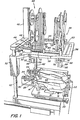
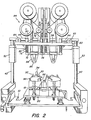
- the operator is intented to stand to the right of the machine as seen in figure 1 and in front of the machine as seen in figure 2.
- the machine is intended to operate on a left foot shoe assembly and a right foot shoe assembly.
- the machine therefore has two sets of mechanisms for operating on the shoe assemblies which are substantially duplicates of each other. Therefore in the following description, it is to be understood that while reference is made to one mechanism this mechanism is duplicated in the machine.
- the machine includes a plate 10 having a last support 12 mounted to its top.
- the last support 12 comprises a toe res 14, a last pin 16, and bars 18, affixed to a bracket 20, that extend in forward-rearward directions on opposite sides of the last pin 16.
- a forked'heel aligner 22 is located forwardly of the last pin 16 and is mounted to the plate 10 in the manner shown in application No. 262,665.
- a toe aligner 24 is mounted to the plate 10 and is located rearwardly of the toe rest 14 on a bar 26.
- 262,665 includes a plate 28, a front aligner plate 30 mounted to and located forwardly of the plate 28, and side aligner pins 32.
- An upwardly concave cam 34 is mounted to the top of the plate 28.
- the cam 34 has a relatively short front leg 36 and a relatively long back leg 38, the legs 36 and 38 extending upwardly of a depression 40 located between the legs.
- a pair of posts 42 are located on opposite sides of and extend upwardly of the plate 10.
- a cross plate 44 extends between and is fixedly mounted to the posts 42.
- a pneumatic motor 46 is mounted to the center of the cross plate 44.
- the downwardly directed piston rod 48 of the motor 46 is secured to a frame 50.
- Bearings 52 of the frame 50 are slidable on the posts 42 to guide the frame 50 for heightwise movement in response to actuations of the motor 46.
- the frame 50 has a back 54 to which the piston rod 48 is secured, a front 56, and sides 58.
- a front cross support 60 fixedly secured to the sides 58, extends between the sides 58 rearwardly of the front 56.
- a back cross support 62 extends between the sides 58 forwardly of the back 54 and rearwardly of the cross support 60.
- -A rod 64 is mounted to one of the sides 58 and a rod 65 is mounted to the other side 58, the rods 64 and 65 extending in forward-rearward directions over their associated sides.
- a sleeve 66 is slidably mounted on each of the rods 64 and 65 and is fixed to the back cross support 62 to thereby mount the support 62 for forward-rearward movement.
- a back collar 68 and a front collar 70 are secured to the rod 64 and a compression spring 72 is entwined about the rod 64 between the collar 70 and the sleeve 66 on the rod 64 to thereby yieldably urge this sleeve 66, together with the back cross support 62, rearwardly against the collar 68.
- a pair of spaced sleeves 74 are fixedly mounted to the front support 60.
- a rod 76 extends through each sleeve 74 and downwardly of the front support 60.
- the bottoms of the rods 76 are secured to a plate 78 and a cap 80 is secured to the top of each rod 76 and overlies its associated sleeve 74.
- a compression spring 82 is entwined about each rod 76 between the plate 78 and the front support 60 to yieldably urge the plate 78 downwardly to a limit determined by the engagement of the caps 80 with the tops'of the sleeves 74.
- a front adhesive applying mechanism 84 is mounted to the plate 78.
- the adhesive applying mechanism 84 is constructed similarly to the front adhesive applying mechanism 346 of application no. 262665 with the plate 78 corresponding to the plate 360 of application no. 262665.
- the adhesive applying mechanism 84 includes an applicator pad 86 corresponding to the applicator 378 of application no. 262665.
- a back adhesive applying mechanism 88 constructed similarly to the back adhesive applying mechanism 354 of application no. 262665, is mounted to the back support 62 in substantially the same manner as the mounting of the front adhesive applying mechanism 84 to the front support 60.
- the back adhesive applying mechanism 88 also includes a plate 78, that is yieldably urged downwardly of the back support 62 by springs 82, and an applicator pad 89.
- a tube 90 is rigidly mounted to the back support 62 and extends downwardly thereof rearwardly of the applicator pad 89 and a cam follower 92 is so mounted in the tube 90 as to be yieldably urged downwardly of the tube 90 by a spring in the tube 90. As shown most clearly in Figure 3, the cam follower 92 is in general registration with the cam 34.
- the piston rod 48 is retracted into the motor 46 so that the frame 50 and the adhesive applying mechanisms 84 and 88 are in upper positions.
- a last 94 is so placed bottom-up on the last support 12 that the last pin 16 enters the thimble hole in the last 94, the forepart of the last 94 is supported on the toe rest 14 and the bars 18 support the sides of the heel portion of the last 94.
- the toe of the last faces rearwardly and the heel of the last faces forwardly.
- the heel aligner 22 in a forward position disengaged from the last 94 and the toe aligner 24 is so set that the aligner plate 30 is in a rearward position and the aligner pins 32 are in outer positions disengaged from the last 94.
- the heel aligner 22 is moved rearwardly into engagement with the heel end of the last 94 and the toe aligner 24 is so actuated as to move the aligner plate 30 forwardly into engagement with the toe end of the last 94 and as to move the aligner pins 32 inwardly into engagement with the sides of the forepart of the last 94.
- This forward movement of the aligner plate 30 acts to also move the cam 34 forwardly to a position determined by the location of the toe end of the last 94.
- the motor 46 is actuated to lower its piston rod 48 to thereby lower the frame 50 into a lower position which causes a lowering of the adhesive applying mechanisms 84 and 88.
- the back adhesive applying mechanism 88 is in a relatively rearward position determined by the position of engagement of the sleeve 66 with the collar 68 under the influence of the spring 72.
- the cam 34, the aligner plate 30 and the cam follower 92 are so related that at this time.
- the cam follower 92 is situated above the back leg 38 of the cam 34 so that, pursuant to the lowering of the back adhesive applying mechanism 88, the cam follower 92 will engage the back leg 38, the specific forward-rearward area of this engagement being dependent on the forward-rearward position of the aligner plate 30 in its position of engagement with the toe end of the last 94.
- the position of engagement of the aligner plate 30 with the toe end of the last 94 is dependent on the forward-rearward distance between the last pin 16 and the toe end of the last 94 and, therefore, upon the length of the last 94.
- This forward movement of the cam follower 92 causes corresponding forward movement of the back adhesive applying mechanism 88 including the applicator pad 89, with the sleeve 66 moving forwardly against the force of the spring 72.
- the pads 86 and 89 continue to descend along with the frame 50 with the cam follower 92 retracting into the tube 90 until the applicator pad 86 engages the heel seat portion of the bottom of the last 94 and the applicator pad 89 engages the forepart portion of the bottom of the last 94 close to and heelwardly of the toe end extremity of the last bottom.
- the continued downward movement of the frame 50 causes the plate 78 associated with the front adhesive applying mechanism 84 and its associated rods 76 and the front adhesive applying mechanism 84 to rise against the force of its associated springs 82.
- the continued downward movement of the frame 50 causes the plate 78 associated with the back adhesive applying mechanism 88 and its associated rods 76 and the back adhesive applying mechanism 88 to rise against the force of its associated springs 82.
- the motor 46 is actuated to raise the piston rod 48 to thereby raise the frame 50 and the adhesive applying mechanisms 84 and 88 to their idle positions with the applicator pads 86 and 89 rising away from the bottom of the last 94.
- a tape 96 is draped about each of the applicator pads 86 and 89.
- the tape 96 is so constituted as to transfer a patch of adhesive therefrom onto the last bottom pursuant to the engagement of the applicator pads 86 and 89 with the last bottom.
- the adhesive patch transferred by the applicator pad 86 is located on the heel seat portion of the last bottom.
- the adhesive patch transferred by the applicator pad 89 because of the aforementioned coaction of the cam follower 92 with the cam 34 and the aforementioned position of the aligner plate 30 and the cam depression 40 with respect to the toe end extremity of the last 94, will be close to and heelwardly of the toe end extremity of the last 94 regardless of the length of the last.
- the heel aligner 22 and the toe aligner 24 are returned to their idle positions so that the heel aligner and the aligner plate 30 and the aligner pins 32 are disengaged from the last 94.
- the machine molds an initially flat insole 98 to a shape that is at least approximately the shape of the bottom of the last 94, enables the molded insole to be placed on the last bottom and so positions that plate 10 and the last 94, as shown in Figures 2 and 3, that they bear the same relationship to the frame 50 and the adhesive applying mechanisms 84 and 88 as they did when the adhesive patches were transferred onto the last bottom by the adhesive applying members 86 and 89.
- the heel aligner 22 is again moved rearwardly into engagement with the heel end of the last 94 and the toe aligner 24 is again actuated as to move the aligner plate 30 into engagement with the toe end of the last 94 and as to move the aligner pins 32 inwardly into engagement with the sides of the last 94.
- These engagements of the members 22, 30 and 32 with the last 94 shift the insole 98, if it is not in exact registry with the last bottom, into exact registry with the last bottom.
- the motor 46 is again actuated to lower and then raise its piston rod 48 to cause a lowering and raising of the frame 50 and the adhesive applying mechanisms 84 and 88 as described above to cause the applicator pads 86 and 89 to engage and apply pressure to the insole 98 above the adhesive patches that were previously applied to the last bottom, and to then cause the raising of the applicator pads 86 and 89.
- This pressure applied by the applicator pads 86 and 89 functions to press the insole 98 against the last bottom and cause the insole 98 to adhere to the last bottom by means of the adhesive patches. This is followed by the return of the heel aligner 22 and the toe aligner 24 to their idle positions.
- the machine cycle is now completed and the last 94 with the molded insole 98 secured to its bottom by the adhesive patches is removed from the machine.
- a shoe is completed on the last and the completed shoe is separated from the last.
- the insole is separated from the last bottom, thus breaking the bond between the last bottom and the insole formed by the adhesive patches.
- remnants of the adhesive patches may remain on the insole and irritate the foot of the wearer of the shoe.
- this patch is applied close to the toe end of the insole where it is unlikely to be engaged by the wearer's foot.
- the heel seat portion of the insole is usually covered by a heel pad that protects the wearer's foot from being irritated by the adhesive patch applied by the applicator pad 86.
- the machine has the purpose of applying a patch of adhesive onto the bottom of the last 94 prior to bonding the insole 98 to the last bottom by means of the adhesive patch.
- the machine comprises: the last support 12 for supporting the last 94 bottom-up with its toe end facing rearwardly; the adhesive applying member 89, located above the last bottom, mounted for heightwise movement; the toe end contacting member 30 mounted for yieldable forward movement from a rearward idle position spaced from the toe end of the last 94 into a position of engagement with the toe end of the last; means, comprised of the motor 46 and its appropriate controls (not shown) for initially positioning the adhesive applying member 89 in an upper idle position spaced from the last bottom; and means, comprised of the motor 46 and its appropriate controls (not shown) for thereafter effecting downward movement of the adhesive applying member 89 towards the last bottom to enable the adhesive applying member 89 to engage the last bottom and apply the patch of adhesive onto the last bottom.
- the machine described in the preceding paragraph is improved, in accordance with this invention, by comprising: means, shown in application no. 262665, for yieldably moving the toe end contacting member 30 forwardly from its idle position into engagement with the toe end of the last 94 prior to effecting the downward movement of the adhesive applying member 89; means, comprised of the rod 64 and the sleeve 66, mounting the adhesive applying member 89 for forward-rearward movement; means, formed by the spring 72, yieldably urging the adhesive applying member 89 to a rearward position; and cooperative shifting means, comprised of the cam 34 and the cam follower 92, mounted to the toe end contacting member 30 and mounted for heightwise movement with the adhesive applying member 89 effective to shift the adhesive applying member 89 forwardly during its downward movement an amount such as to cause the adhesive applying member 89 to engage the last bottom close to and rearwardly of the toe end of the last bottom.
- the cooperative shifting means comprises: the cam 34, mounted to the toe end contacting member 30 for forward-rearward movement therewith, having an upper surface on its leg 38 that slopes downwardly and forwardly into the depression 40; and the cam follower 92 so mounted for heightwise and forward-rearward movement in unison with the adhesive applying member 89 that it is in heightwise registry with the cam 34 when the toe end contacting member 30 is in engagement with the toe end of the last 94; whereby during the downward movement of the adhesive applying member 89 the cam follower 92 engages the cam 34 and moves forwardly along said upper surface into the depression 40 to thereby shift the adhesive applying member 89 forwardly as aforesaid.
Landscapes
- Orthopedics, Nursing, And Contraception (AREA)
- Footwear And Its Accessory, Manufacturing Method And Apparatuses (AREA)
Applications Claiming Priority (2)
| Application Number | Priority Date | Filing Date | Title |
|---|---|---|---|
| US287339 | 1981-07-27 | ||
| US06/287,339 US4373467A (en) | 1981-07-27 | 1981-07-27 | Machine for applying a patch of adhesive onto the bottom of a last |
Publications (3)
| Publication Number | Publication Date |
|---|---|
| EP0071394A2 true EP0071394A2 (de) | 1983-02-09 |
| EP0071394A3 EP0071394A3 (en) | 1984-07-18 |
| EP0071394B1 EP0071394B1 (de) | 1986-03-26 |
Family
ID=23102473
Family Applications (1)
| Application Number | Title | Priority Date | Filing Date |
|---|---|---|---|
| EP82303817A Expired EP0071394B1 (de) | 1981-07-27 | 1982-07-21 | Maschine zum Auftragen eines Klebstoffstreifens auf den Boden eines Leistens |
Country Status (7)
| Country | Link |
|---|---|
| US (1) | US4373467A (de) |
| EP (1) | EP0071394B1 (de) |
| JP (1) | JPS5827502A (de) |
| BR (1) | BR8203783A (de) |
| CA (1) | CA1174811A (de) |
| DE (1) | DE3270099D1 (de) |
| SU (1) | SU1237067A3 (de) |
Families Citing this family (3)
| Publication number | Priority date | Publication date | Assignee | Title |
|---|---|---|---|---|
| EP0364801A1 (de) * | 1988-10-06 | 1990-04-25 | Lasag Ag | Vorrichtung zur chirurgischen Behandlung einer Stelle im Auge |
| GB9017782D0 (en) * | 1990-08-14 | 1990-09-26 | British United Shoe Machinery | Machine for applying adhesive progressively along marginal portions of shoe bottom |
| CN110013946B (zh) * | 2019-04-29 | 2021-09-10 | 陈俊 | 一种双工位自动涂胶生产线 |
Family Cites Families (3)
| Publication number | Priority date | Publication date | Assignee | Title |
|---|---|---|---|---|
| US3107376A (en) * | 1963-03-18 | 1963-10-22 | Bain Corp | Apparatus for assembling an insole and last in aligned relation |
| US3513495A (en) * | 1967-10-19 | 1970-05-26 | Kamborian Jacob S | Apparatus for temporarily attaching an insole to a last |
| US3653356A (en) * | 1970-09-02 | 1972-04-04 | Kamborian Jacob S | Coating machine |
-
1981
- 1981-07-27 US US06/287,339 patent/US4373467A/en not_active Expired - Lifetime
-
1982
- 1982-06-29 BR BR8203783A patent/BR8203783A/pt unknown
- 1982-07-15 CA CA000407329A patent/CA1174811A/en not_active Expired
- 1982-07-21 EP EP82303817A patent/EP0071394B1/de not_active Expired
- 1982-07-21 JP JP57125933A patent/JPS5827502A/ja active Pending
- 1982-07-21 DE DE8282303817T patent/DE3270099D1/de not_active Expired
- 1982-07-27 SU SU823467839A patent/SU1237067A3/ru active
Also Published As
| Publication number | Publication date |
|---|---|
| JPS5827502A (ja) | 1983-02-18 |
| EP0071394A3 (en) | 1984-07-18 |
| CA1174811A (en) | 1984-09-25 |
| BR8203783A (pt) | 1983-06-21 |
| US4373467A (en) | 1983-02-15 |
| EP0071394B1 (de) | 1986-03-26 |
| SU1237067A3 (ru) | 1986-06-07 |
| DE3270099D1 (en) | 1986-04-30 |
Similar Documents
| Publication | Publication Date | Title |
|---|---|---|
| EP0071394B1 (de) | Maschine zum Auftragen eines Klebstoffstreifens auf den Boden eines Leistens | |
| US2730733A (en) | Heel lasting machines | |
| EP0100636B1 (de) | Zwickmaschine für den Zehenbereich mit einstellbarer Fersenhalterung | |
| US4389745A (en) | Molding an insole and attaching the molded insole to a last bottom | |
| GB2055036A (en) | Rough moulding shaper for the rear portion of footwear | |
| US2869155A (en) | Heel and shank lasting machines | |
| US2338764A (en) | Sole-laying machine | |
| US2406463A (en) | Lasting machine | |
| US3439367A (en) | Temporarily securing a shoe sole to a shoe form | |
| US3091784A (en) | Toe lasting machines | |
| US4744120A (en) | Shoe support for shoe upper conforming machine | |
| US2422737A (en) | Method of and machine for turning the platform covers of platform shoes | |
| US3178742A (en) | Lasting machine | |
| US3056149A (en) | Machines for attaching flap portions of loose outsoles to the breasts of loose louisheels | |
| US3300799A (en) | Upper shaping machines | |
| US3422476A (en) | Method and apparatus for clamping an end of a shoe assembly | |
| US3628207A (en) | Control system interconnecting the operation of two machines | |
| US2923953A (en) | courchene | |
| US3120014A (en) | Last support | |
| US3081469A (en) | Machines for applying simultaneous pressures to the bottom and heel breast of a shoe | |
| US3727257A (en) | Apparatus for making shoes | |
| US3613138A (en) | Method for making shoes | |
| US3075209A (en) | Machines for attaching loose outsoles to the breasts of loose louis heels | |
| US2263699A (en) | Machine for lasting the toe portion of uppers in the manufacture of shoes | |
| EP0093608A1 (de) | Werkstück-Transporteinrichtung |
Legal Events
| Date | Code | Title | Description |
|---|---|---|---|
| PUAI | Public reference made under article 153(3) epc to a published international application that has entered the european phase |
Free format text: ORIGINAL CODE: 0009012 |
|
| AK | Designated contracting states |
Designated state(s): DE FR GB IT |
|
| 17P | Request for examination filed |
Effective date: 19830716 |
|
| PUAL | Search report despatched |
Free format text: ORIGINAL CODE: 0009013 |
|
| AK | Designated contracting states |
Designated state(s): DE FR GB IT |
|
| ITF | It: translation for a ep patent filed | ||
| GRAA | (expected) grant |
Free format text: ORIGINAL CODE: 0009210 |
|
| AK | Designated contracting states |
Kind code of ref document: B1 Designated state(s): DE FR GB IT |
|
| REF | Corresponds to: |
Ref document number: 3270099 Country of ref document: DE Date of ref document: 19860430 |
|
| ET | Fr: translation filed | ||
| PLBE | No opposition filed within time limit |
Free format text: ORIGINAL CODE: 0009261 |
|
| STAA | Information on the status of an ep patent application or granted ep patent |
Free format text: STATUS: NO OPPOSITION FILED WITHIN TIME LIMIT |
|
| 26N | No opposition filed | ||
| PG25 | Lapsed in a contracting state [announced via postgrant information from national office to epo] |
Ref country code: FR Free format text: LAPSE BECAUSE OF NON-PAYMENT OF DUE FEES Effective date: 19880331 |
|
| PG25 | Lapsed in a contracting state [announced via postgrant information from national office to epo] |
Ref country code: DE Effective date: 19880401 |
|
| GBPC | Gb: european patent ceased through non-payment of renewal fee | ||
| REG | Reference to a national code |
Ref country code: FR Ref legal event code: ST |
|
| PG25 | Lapsed in a contracting state [announced via postgrant information from national office to epo] |
Ref country code: GB Free format text: LAPSE BECAUSE OF NON-PAYMENT OF DUE FEES Effective date: 19881121 |