EP0071406B1 - Schlauchförmige Ankerleine - Google Patents
Schlauchförmige Ankerleine Download PDFInfo
- Publication number
- EP0071406B1 EP0071406B1 EP82303856A EP82303856A EP0071406B1 EP 0071406 B1 EP0071406 B1 EP 0071406B1 EP 82303856 A EP82303856 A EP 82303856A EP 82303856 A EP82303856 A EP 82303856A EP 0071406 B1 EP0071406 B1 EP 0071406B1
- Authority
- EP
- European Patent Office
- Prior art keywords
- tube
- mooring line
- mooring
- fluid
- further characterised
- Prior art date
- Legal status (The legal status is an assumption and is not a legal conclusion. Google has not performed a legal analysis and makes no representation as to the accuracy of the status listed.)
- Expired
Links
- 239000007788 liquid Substances 0.000 claims description 30
- 239000012530 fluid Substances 0.000 claims description 23
- 230000000694 effects Effects 0.000 claims description 10
- 239000013536 elastomeric material Substances 0.000 claims description 8
- 230000007935 neutral effect Effects 0.000 claims description 5
- 230000036316 preload Effects 0.000 claims description 5
- 230000008878 coupling Effects 0.000 claims description 4
- 238000010168 coupling process Methods 0.000 claims description 4
- 238000005859 coupling reaction Methods 0.000 claims description 4
- 238000012986 modification Methods 0.000 claims description 3
- 230000004048 modification Effects 0.000 claims description 3
- 238000007789 sealing Methods 0.000 claims description 3
- 239000013589 supplement Substances 0.000 claims description 2
- 229920001971 elastomer Polymers 0.000 description 8
- 239000005060 rubber Substances 0.000 description 8
- 230000007423 decrease Effects 0.000 description 6
- XLYOFNOQVPJJNP-UHFFFAOYSA-N water Substances O XLYOFNOQVPJJNP-UHFFFAOYSA-N 0.000 description 5
- 229910000831 Steel Inorganic materials 0.000 description 4
- 230000003247 decreasing effect Effects 0.000 description 4
- 238000006073 displacement reaction Methods 0.000 description 4
- 239000003365 glass fiber Substances 0.000 description 4
- 239000000463 material Substances 0.000 description 4
- 239000010959 steel Substances 0.000 description 4
- 238000004519 manufacturing process Methods 0.000 description 3
- 229910001209 Low-carbon steel Inorganic materials 0.000 description 2
- 239000004411 aluminium Substances 0.000 description 2
- 229910052782 aluminium Inorganic materials 0.000 description 2
- XAGFODPZIPBFFR-UHFFFAOYSA-N aluminium Chemical compound [Al] XAGFODPZIPBFFR-UHFFFAOYSA-N 0.000 description 2
- 229910052793 cadmium Inorganic materials 0.000 description 2
- BDOSMKKIYDKNTQ-UHFFFAOYSA-N cadmium atom Chemical compound [Cd] BDOSMKKIYDKNTQ-UHFFFAOYSA-N 0.000 description 2
- 238000005260 corrosion Methods 0.000 description 2
- 230000007797 corrosion Effects 0.000 description 2
- 238000013016 damping Methods 0.000 description 2
- 229910003460 diamond Inorganic materials 0.000 description 2
- 239000010432 diamond Substances 0.000 description 2
- 239000000835 fiber Substances 0.000 description 2
- 229910052751 metal Inorganic materials 0.000 description 2
- 239000002184 metal Substances 0.000 description 2
- 125000006850 spacer group Chemical group 0.000 description 2
- OKTJSMMVPCPJKN-UHFFFAOYSA-N Carbon Chemical compound [C] OKTJSMMVPCPJKN-UHFFFAOYSA-N 0.000 description 1
- 239000004593 Epoxy Substances 0.000 description 1
- 239000004677 Nylon Substances 0.000 description 1
- 239000004952 Polyamide Substances 0.000 description 1
- 239000004743 Polypropylene Substances 0.000 description 1
- 229920000297 Rayon Polymers 0.000 description 1
- 229910052799 carbon Inorganic materials 0.000 description 1
- 238000006243 chemical reaction Methods 0.000 description 1
- 238000010276 construction Methods 0.000 description 1
- 230000008602 contraction Effects 0.000 description 1
- 238000011161 development Methods 0.000 description 1
- 238000005553 drilling Methods 0.000 description 1
- 238000009434 installation Methods 0.000 description 1
- 238000011835 investigation Methods 0.000 description 1
- 230000033001 locomotion Effects 0.000 description 1
- 229920003052 natural elastomer Polymers 0.000 description 1
- 229920001194 natural rubber Polymers 0.000 description 1
- 229920001778 nylon Polymers 0.000 description 1
- 230000003534 oscillatory effect Effects 0.000 description 1
- 239000003973 paint Substances 0.000 description 1
- 229920002647 polyamide Polymers 0.000 description 1
- -1 polypropylene Polymers 0.000 description 1
- 229920001155 polypropylene Polymers 0.000 description 1
- 239000002964 rayon Substances 0.000 description 1
- 230000002787 reinforcement Effects 0.000 description 1
- 230000003014 reinforcing effect Effects 0.000 description 1
- 229910001220 stainless steel Inorganic materials 0.000 description 1
- 239000010935 stainless steel Substances 0.000 description 1
- 239000000126 substance Substances 0.000 description 1
- 230000001502 supplementing effect Effects 0.000 description 1
- 229920003051 synthetic elastomer Polymers 0.000 description 1
- 239000005061 synthetic rubber Substances 0.000 description 1
- 238000012360 testing method Methods 0.000 description 1
- 238000004804 winding Methods 0.000 description 1
Images



Classifications
-
- F—MECHANICAL ENGINEERING; LIGHTING; HEATING; WEAPONS; BLASTING
- F03—MACHINES OR ENGINES FOR LIQUIDS; WIND, SPRING, OR WEIGHT MOTORS; PRODUCING MECHANICAL POWER OR A REACTIVE PROPULSIVE THRUST, NOT OTHERWISE PROVIDED FOR
- F03B—MACHINES OR ENGINES FOR LIQUIDS
- F03B13/00—Adaptations of machines or engines for special use; Combinations of machines or engines with driving or driven apparatus; Power stations or aggregates
- F03B13/12—Adaptations of machines or engines for special use; Combinations of machines or engines with driving or driven apparatus; Power stations or aggregates characterised by using wave or tide energy
-
- F—MECHANICAL ENGINEERING; LIGHTING; HEATING; WEAPONS; BLASTING
- F03—MACHINES OR ENGINES FOR LIQUIDS; WIND, SPRING, OR WEIGHT MOTORS; PRODUCING MECHANICAL POWER OR A REACTIVE PROPULSIVE THRUST, NOT OTHERWISE PROVIDED FOR
- F03B—MACHINES OR ENGINES FOR LIQUIDS
- F03B13/00—Adaptations of machines or engines for special use; Combinations of machines or engines with driving or driven apparatus; Power stations or aggregates
- F03B13/12—Adaptations of machines or engines for special use; Combinations of machines or engines with driving or driven apparatus; Power stations or aggregates characterised by using wave or tide energy
- F03B13/14—Adaptations of machines or engines for special use; Combinations of machines or engines with driving or driven apparatus; Power stations or aggregates characterised by using wave or tide energy using wave energy
- F03B13/16—Adaptations of machines or engines for special use; Combinations of machines or engines with driving or driven apparatus; Power stations or aggregates characterised by using wave or tide energy using wave energy using the relative movement between a wave-operated member, i.e. a "wom" and another member, i.e. a reaction member or "rem"
- F03B13/18—Adaptations of machines or engines for special use; Combinations of machines or engines with driving or driven apparatus; Power stations or aggregates characterised by using wave or tide energy using wave energy using the relative movement between a wave-operated member, i.e. a "wom" and another member, i.e. a reaction member or "rem" where the other member, i.e. rem is fixed, at least at one point, with respect to the sea bed or shore
- F03B13/1885—Adaptations of machines or engines for special use; Combinations of machines or engines with driving or driven apparatus; Power stations or aggregates characterised by using wave or tide energy using wave energy using the relative movement between a wave-operated member, i.e. a "wom" and another member, i.e. a reaction member or "rem" where the other member, i.e. rem is fixed, at least at one point, with respect to the sea bed or shore and the wom is tied to the rem
- F03B13/1895—Adaptations of machines or engines for special use; Combinations of machines or engines with driving or driven apparatus; Power stations or aggregates characterised by using wave or tide energy using wave energy using the relative movement between a wave-operated member, i.e. a "wom" and another member, i.e. a reaction member or "rem" where the other member, i.e. rem is fixed, at least at one point, with respect to the sea bed or shore and the wom is tied to the rem where the tie is a tension/compression member
-
- B—PERFORMING OPERATIONS; TRANSPORTING
- B63—SHIPS OR OTHER WATERBORNE VESSELS; RELATED EQUIPMENT
- B63B—SHIPS OR OTHER WATERBORNE VESSELS; EQUIPMENT FOR SHIPPING
- B63B21/00—Tying-up; Shifting, towing, or pushing equipment; Anchoring
-
- B—PERFORMING OPERATIONS; TRANSPORTING
- B63—SHIPS OR OTHER WATERBORNE VESSELS; RELATED EQUIPMENT
- B63B—SHIPS OR OTHER WATERBORNE VESSELS; EQUIPMENT FOR SHIPPING
- B63B21/00—Tying-up; Shifting, towing, or pushing equipment; Anchoring
- B63B2021/001—Mooring bars, yokes, or the like, e.g. comprising articulations on both ends
-
- Y—GENERAL TAGGING OF NEW TECHNOLOGICAL DEVELOPMENTS; GENERAL TAGGING OF CROSS-SECTIONAL TECHNOLOGIES SPANNING OVER SEVERAL SECTIONS OF THE IPC; TECHNICAL SUBJECTS COVERED BY FORMER USPC CROSS-REFERENCE ART COLLECTIONS [XRACs] AND DIGESTS
- Y02—TECHNOLOGIES OR APPLICATIONS FOR MITIGATION OR ADAPTATION AGAINST CLIMATE CHANGE
- Y02E—REDUCTION OF GREENHOUSE GAS [GHG] EMISSIONS, RELATED TO ENERGY GENERATION, TRANSMISSION OR DISTRIBUTION
- Y02E10/00—Energy generation through renewable energy sources
- Y02E10/30—Energy from the sea, e.g. using wave energy or salinity gradient
Definitions
- This invention relates to tie lines, and more particularly to mooring lines, for example for wave energy devices.
- Such mooring lines must be able to withstand large tensile loads, but must be compliant, must not react chemically with water, and should have a relatively long fatigue life despite repeated cycles of stress and relaxation.
- British Patent Specification No: 2053303 describes an elastic tie member, which may be used as a mooring line, comprising an elongate elastomeric body reinforced with co-axial layers of helically wound relatively inelastic filaments. Adjacent pairs of layers are spaced by the elastomeric material and have their filaments wound in opposite handed helical relationship.
- the present invention is a development from that of GB 2053303 and extends significantly the usefulness of the tie member as a mooring line by providing for supplementing in use the elastic properties of the line in resisting an axial load.
- the invention provides a mooring line (which expression includes any line used in the marine field for the control of loads to which it is attached, as for example in towing and in moorings fixed to the sea bed) including a tube of elastomeric material incorporatng relatively inelastic filaments to reinforce the elastomeric material, which filaments extend helically along the length of the tube in at least two layers radially displaced from each other by the elastomeric material, the filaments in a layer extending in an oppositely handed helix with respect to the filaments in an adjacent layer, each helix having a plurality of turns, and at least a substantial proportion of the turns making an angle to the axis of the helix less than the "neutral angle" (that is the helix angle at which the cylindrical volume within a fixed length of filament is a maximum), the tube being adapted to contain a pressurized fluid, and having port means for connecting the tube to means for pressurizing the fluid, whereby the pressurized fluid supplements the elastic properties
- the pressure may be selected in relation to the axial load so that the fluid produces at least a substantial proportion of the restoring force for decreasing the length of the tube as the axial load relaxes.
- the fluid in the tube may be a gas, and the pressure means may be a source of pressurized gas.
- the fluid in the tube may comprise a liquid, and the pressure means a hydro-pneumatic accumulator.
- the hydro-pneumatic accumulator may comprise a cylinder having a piston member therein, and a port at each end of the cylinder, the stroke of the piston member being arranged to close the respective port at the one end and/or at the other end of the stroke.
- Each of the ends of the tube may be held by a respective coupling means comprising, a plug member at least partly of truncated conical form having a bore therethrough and about which plug member the tube is locatable, an end member against which the plug member is locatable, the end member having a duct communicable with the bore of the plug member and with the port means, sealing means on the plug member and arranged to abut the end member, and a clamping member adapted to bear against the conical surface at said one end of the tube and to engage the end member, thereby to urge the tube on to the plug member and towards the end member.
- the invention also includes an electric power system comprising a mooring line of the invention, and a turbine means arranged to be driven by the fluid displaced by the mooring line.
- the elastomeric material may be natural or synthetic rubber, and the filaments may be of steel, carbon fibre, natural fibre, rayon, nylon, polyamide, polypropylene, or glass-fibre.
- a mooring line comprising a tube 10 having a bore 13 and pivotally connected between an upper pivotal mounting 11 and a lower pivotal mounting 12.
- the tube 10 is made of vulcanised rubber 14 and incorporates reinforcement in the form of an inner cylindrical layer 16 and a co-axial outer cylindrical layer 17 of helically wound glass-fibre filaments 18.
- the inner layer 16 is separated from the outer layer 17 by the rubber 14, and the filaments 18 in the inner layer 16 are wound in an opposite-handed relationship to the filaments 18 in the outer layer 17.
- the filaments 18 make an angle of about 45° with the longitudinal axis of the tube 10.
- Each end of the tube 10 has an end-fitting 20, 21 connected to a pivot pin 28, 29 at the respective pivotal mounting 11, 12.
- the volume enclosed by a single helically wound filament 18 depends on the angle between the filament 18 and the axis of the helix, and is a maximum when the angle is equal to arc sec V3 (approximately 55°) and herein called the "neutral angle". If the length of the helix is increased the angle decreases and so for a helix in which the filaments 18 make an angle to the axis of less than the neutral angle an increase in the length of the . helix leads to a decrease in the volume enclosed.
- the tube 10 used as a mooring line and the cylinder 25 and the bore 13 containing a pressurized gas e.g. air
- a pressurized gas e.g. air
- the application of a varying external axial tensile load on the tube 10 by displacement of the upper mounting 11 causes the tube 10 to lengthen when the load increases, with a consequent decrease in the volume of the bore 13 causing an increase in the gas pressure in the bore 13.
- the gas pressure provides the restoring force to increase the volume of the bore 13 and pull the upper mounting 11 back towards the lower mounting 12.
- the gas in the cylinder 25 and in the bore 13 acts as a spring reacting to the external load on the tube 10, with the flow-restricting valve 23 providing a damping effect on this spring action.
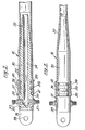
- the tube 10 For ease of manufacture it is convenient to produce the tube 10 from continuous lengths of tubing which can be cut to the length required for a particular application. The tube 10 will then be joined to the lower and to the upper end-fittings 20, 21, and in Figure 2 there is shown an example of a suitable lower end-fitting 21.
- the lower end-fitting 21 is made of a rigid material such as steel and comprises a cylindrical body portion 30 of diameter slightly greater than that of the axially unstrained tube 10 and having three circumferential grooves 31a, 31b, 31c, a co-axial conical body portion 32 extending from one end of the cylindrical body portion 30, and an end portion 33 of square cross-section being joined to the other end of the cylindrical body portion 30.
- the end portion 33 includes a tang 36 having a hole 39 to locate the tang 36 on the pivot pin 29.
- the duct 22 through the end-fitting 21 is provided by a cylindrical hole 34 which extends axially through the conical body portion 32 and the cylindrical body portion 30 into the end portion 33 and communicates with a transverse hole 35 through the end portion 33 perpendicular to the cylindrical hole 34.
- the two ends of the transverse hole 35 are threaded to locate pipe connections 37, one of which may be connected to the pipe line 24 and the other closed by a plug (not shown).
- the upper end-fitting 20 is the same as the lower end-fitting 21 except that the duct 22 is omitted.
- an end portion 38 of the tube 10 is fitted over the conical body portion 32 and the cylindrical body portion 30, and is clamped thereto by a metal ferrule 40 which depresses part of the end portion 38 of the tube 10 into the circumferential grooves 31a, 31b and has a lip 41 which locates in the circumferential groove 31c.
- the tube 10 is shown subjected to an axial load so that its diameter has decreased such that the tube 10 increases its grip on the conical body portion 32.
- the cone angle of the conical body portion 32 is chosen so that as the axial load increases the tube 10 deforms tightly around a gradually increasing length of the conical body portion 32, the length of the interface between the tube 10 and the end fitting 21 being designed to limit the shear stress in the rubber 14 of the tube 10 to an acceptable value in the vicinity of the end fitting 21 while enabling sufficient frictional grip to be produced to withstand the axial load.
- the advantages of the end-fitting 21 are that, as the axial tension in the tube 10 increases so too does the area of contact between the tube 10 and the end-fitting 21, and also abrupt changes in curvature of the rubber 14 are avoided at the end of the end-fitting 21. Furthermore, if internal pressure is applied inside the tube 10 with the end fittings 20, 21 attached and the tube 10 at its unstrained length, the internal pressure induces an axial tension in the tube 10 tending to shorten the tube 10, and owing to the effect of the helically wound filaments 18 the tube 10 grips the cylindrical body portion 30 of the end fittings 20, 21 more firmly as it resists the induced axial tension. This effect will apply even if the angles between the filaments 18 and the axis of the tube 10 are equal to or greater than the neutral angle in the vicinity of the cylindrical body portion 30 as a result of local distortion of the tube 10 as it is fitted over the cylindrical body portion 30.
- Figure 4 shows an alternative type of mooring line differing from that of Figure 1 only in that the bore 13 of the tube 10 is full of liquid 50 pressurized by a hydro-pneumatic accumulator 51.
- the pipe line 24 is now connected to a liquid port 54 at one end of the accumulator 51, and the other end of the accumulator 51 communicates through a gas port 53 to a gas line 52 connected to the gas cylinder 25 which contains a pressurized gas 56.
- the accumulator 51 contains a movable piston 55 which separates the liquid 50 from the gas 56, and when the piston 55 is at the lower end of its stroke it closes the liquid port 54 and prevents the gas 56 from the gas cylinder 25 from entering the pipe line 24, and when at the upper end of its stroke the piston 55 closes the gas port 53 and prevents the liquid 50 from the tube 10 from entering the gas line 52.
- the mooring line shown in Figure 4 has a spring characteristic similar to that of the mooring line of Figure 1, but can have the additional features of a pre-load at zero extension, and a stiff end-cushion effect at large extensions, obtainable as follows, with reference to the graph of Figure 4a.
- the tube 10 In the initial state there is no axial tensile load on the tube 10, and the piston 55 is at the lower end of its stroke, closing the liquid port 54. If the liquid 50 in the tube 10 is initially at a lower pressure than the gas 56 in the accumulator 51, then as an increasing load is applied to the mooring line, the tube 10 will not extend (stage A) until the pressure of the liquid 50 within it reaches the value of the gas pressure in the accumulator 51, this occurring at a load L constituting the preload. The tube 10 will then extend (stage B) causing the volume of the bore 13 to decrease, thereby displacing the liquid 50 from the tube 10 into the accumulator 51 and causing the piston 55 to rise.
- stage C the mooring line will have no pre-load, but will otherwise react to an increasing load in the same manner.
- the angle of the helical windings to the axis and the pressure within the tube 10 have the values 45° and 10 MPa respectively, while at point Q on the graph the corresponding values are 30° and 20 MPa.
- the mooring lines of Figures 1 and 4 may be used to moor a buoyant wave energy device (not shown).
- An example is for the mooring of a wave energy conversion device of the type described in British Patent Specification No. 1580805.
- the body of the device is referred to as the hull and in this example is 220 m long.
- Four identical mooring lines, one to each corner of the hull, are connected to two anchorages, with the two lines from either end of each side of the hull sharing an anchorage opposite the mid-point of the hull and displaced some 175 metres from it.
- the lines in plan therefore form a diamond with the hull acting as one diagonal.
- Each line is a 200 m long tube 10 with 10 m long end fittings 20, 21, and the anchorage is a drilled and grouted pile. A pre-tension of 250 tonnes will provide that the line should never go slack and so should avoid snatch loading.
- the moorings are designed for a range of water depths from 60 to 80 metres.
- the “diamond" layout was initially chosen for its simplicity and flexibility but was found on investigation to produce a very stable mooring system.
- the geometry of the layout minimises the angular rotation in plan between the device hull and the mooring lines, thus simplifying the mooring joint detail.
- the mooring layout leaves the sea ahead and astern of the devices free of obstructions to shipping and keeps the mooring lines well clear of the power cables which are connected at the ends of the hull and run on a lazy 'S' from one device to the next.
- the tubes 10 are connected to the hulls nine metres below the still water level, the water surface is not obstructed for the shallow draught vessels used during the installation procedure.
- the mooring line may be combined with means for generating electric power, an arrangement which may be particularly suitable where used for mooring a wave energy device as described above.
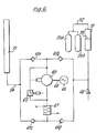
- An example is illustrated in diagrammatic form in Figure 6 which shows an electric power system comprising the mooring line of Figure 4 and a uni-directional hydro-turbine 60 connected into the pipe-line 24 between the tube 10 and the accumulator 51, the flow restricting valve 23 being omitted from the system.
- the accumulator 51 is pressurized by two gas cylinders 25a, 25b connected in parallel to the gas-line 52.
- the flow of the liquid 50 e.g.
- the turbine 60 which is preferably of the Francis type, is joined by a shaft 64 to an alternator 65.
- the system also includes a heat exchanger 67 to dissipate heat from the liquid 50 produced as a result of system losses, and it is advisable to provide an inlet 68 for the initial charging of the system with the liquid ,50 and for any subsequent make-up of the liquid 50.
- the turbine 60, alternator 65, accumulator 51 and gas cylinders 25a, 25b could form a compact module to be mounted on a structure (not shown) adjacent to the pivotal mounting 12 of the mooring line of Figure 4.
- the gas pressure in the accumulator 51 causes the liquid 50 to flow out of the accumulator 51, through the pipe line 24, the valve 61b, the turbine 60, the heat exchanger 67, the valve 61c, and into the tube 10, thus decreasing the length of the tube 10 due to the increase in volume of the bore 13.
- the liquid 50 is forced to flow in alternate directions between the tube 10 and the accumulator 51, the flow being rectified by the valves 61a, 61b, 61c, 61d so as to produce uni-directional flow of the liquid 50 through the turbine 60.
- the piston 55 can be omitted, although the characteristics of the pre-load L and the stiff end cushion effect C would thereby be lost.
- the piston 55 may sealingly separate the liquid 50 from the gas 56, or it may float on the surface of the liquid 50 in a substantially vertical accumulator 51.
- the additional damping provided by the flow-restricting valve 23 may not be necessary, and the valve 23 may be omitted.
- a gas cylinder 25 and an accumulator 51 might be dispensed with, the tube 10 being pressurized with a fluid and subsequently being sealed, for example by the valve 23 in Figure 1 to provide a particular tension/extension characteristic of the mooring line.
- the fluid might comprise a gas, and a proportion of the tube 10 might be filled with a liquid.
- the spring characteristic of the mooring line may be controlled over a wide range by varying the volume of gas in the tube 10 or connected to it externally in gas cylinders 25.
- the spring rate may be increased by partially filling the tube 10 with liquid or may be decreased by connecting the tube 10 to external gas storage (as in cylinders 25).
- the extension against load curve may be altered by controlling the gas pressure.
- the object is held in position by an array of mooring lines pretensioned to prevent them going slack and causing snatch loading.
- the use of the mooring line of the examples of the present invention enables the pre-tension to be applied by pressurizing the tube 10 after the mooring line has been attached at each end, the pressurization causing the tube 10 to contract and tighten the line.
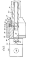
- FIG. 7 a coupling device in the form of a lower end-fitting 70 is shown constructed essentially from a rigid material such as steel, and comprising a conical plug 72 having a cylindrical spigot 74 which locates as a clearance fit in a duct 76 of an end member 78.
- the plug 72 has a conical included angle of about 10°, and has an axial bore 80 therethrough to connect with the duct 76.
- a vulcanised rubber tube 10a similar in most respects to the tube 10 of Figures 1 and 1a, locates about the plug 72 but at an end 82 of the tube 10a adjacent to the end member 78 an aluminium ferrule 84 having a rounded end 85 is encased in the tube 10a at the end 82.
- helically wound glass-fibre filaments (not shown) extending along the tube 10a are wound round the ferrule 84 and then wound back on the tube 10a far enough for a strong bond to be formed when the rubber of the tube 10a is cured.
- the ferrule 84 is positioned divergent with respect to the end 82 of the tube 10a, having an inner surface 87 of the same conical angle as that of the plug 72 and a wedge angle typically of about 20°, to arrange that the end 82 is of conical form and becomes trapped between an inner conical face 86 of an internally threaded connector 88 and the plug 72.
- a steel spacer ring 90 on the spigot 74 has a thickness selected to take up manufacturing tolerances at the tube end 82, and an '0' ring seal 92 on the spacer ring 90 is compressed between the tube end 82 and the end member 78 to maintain a fluid-tight seal under conditions of light or zero tension in the tube 10a.
- the connector 88 engages a threaded portion 94 of the end member 78 and is held thereon by a lock nut 96.
- the duct 76 of the body 78 communicates with a transverse hole 98 at a square-shaped portion 102 of the end member 78, each end 104 (only one is shown) of the hole 98 being threaded to locate pipe connections (not shown).
- An upper end fitting (not shown) may be made the same as the lower end-fitting 70 except that the duct 76, and the bore 80 are omitted.
- the ferrule 84 is made from a corrosion resistant material to resist chemical attack during the construction of the tube 10a, and suitable alternative materials to aluminium may be used, for example cadmium plated mild steel.
- the end fitting 70 may be made generally from a cadmium plated mild steel, and subsequently treated with an epoxy paint. However, if desired a more corrosion resistant metal such as stainless steel may be used.
- the wedge angle of the ferrule 84 is not critical, and may be selected in conjunction with the conical angle of the conical face 86 to provide a required relationship of axial displacement and radial load. If desired, the included angle of the plug 72 may also be changed.
- the plug 72 is formed with, a cylindrical portion extending from the end adjacent the end member 78 through a predetermined axial distance (see below), and a conical portion from this cylindrical portion to the end of the plug 72 within the tube 10a.
- the ferrule 84 is made with a cylindrical inner surface 87 but has the same wedge angle (-20°).
- the axial extent of the cylindrical portion of the plug 72 is arranged at least to coincide with the extent of the folded over portion of the tube 10a. This modified arrangement reduces the stress in the folded portion of the tube 10a which arises because the helical filaments in the portion folded back are of opposite hand to those in the main body of the tube.
- An alternative electric power system could combine the mooring line of Figure 1 with a gas turbine (notshown), and it will be understood that although the electric power system has been described as including a uni-directional turbine 60 and a rectifying arrangement of non-return valves 61a, 61b, 61c, 61d, a bi-directional turbine may be used instead, the non-return valves 61a, 61b, 61c, 61 d being omitted.
- the mooring line also has a number of other applications.
- the stiffness of the mooring array can be adjusted to suit operating conditions by varying the pressure and volume of the connected gas storage.
- Positional control may be effected by differential adjustment of the mooring lines by changes in gas pressure to adjust the length of a mooring line.
- a large tanker to a jetty ten or more lines may be required and these all have to be adjusted frequently by winches to compensate for tidal changes and loading conditions.
- the high compliance of the tube mooring lines of the present invention should reduce changes in load, and adjustments may be effected by control of gas pressure, thereby eliminating the need to operate the winches.
- a tube mooring line of the present invention used in series with a conventional towing rope for ship towing would by virtue of its high compliance and strain capacity, reduce snatch loads.
- the high compliance (which reduces loads) and longer life expectancy of the tube mooring line of the present invention may also be expected to make it a more cost effective mooring line for large buoys than conventional moorings.
- the invention provides a tie line comprising a tubular elastic member arranged to be internally pressurized by fluid means.
Landscapes
- Engineering & Computer Science (AREA)
- Chemical & Material Sciences (AREA)
- Combustion & Propulsion (AREA)
- Mechanical Engineering (AREA)
- General Engineering & Computer Science (AREA)
- Ocean & Marine Engineering (AREA)
- Rigid Pipes And Flexible Pipes (AREA)
- Electrical Discharge Machining, Electrochemical Machining, And Combined Machining (AREA)
Claims (20)
Applications Claiming Priority (4)
| Application Number | Priority Date | Filing Date | Title |
|---|---|---|---|
| GB8123128 | 1981-07-27 | ||
| GB8123128 | 1981-07-27 | ||
| GB08219453A GB2113733B (en) | 1981-07-27 | 1982-07-06 | Tube mooring line |
| GB8219453 | 1982-07-06 |
Publications (3)
| Publication Number | Publication Date |
|---|---|
| EP0071406A2 EP0071406A2 (de) | 1983-02-09 |
| EP0071406A3 EP0071406A3 (en) | 1983-09-14 |
| EP0071406B1 true EP0071406B1 (de) | 1985-10-09 |
Family
ID=26280273
Family Applications (1)
| Application Number | Title | Priority Date | Filing Date |
|---|---|---|---|
| EP82303856A Expired EP0071406B1 (de) | 1981-07-27 | 1982-07-21 | Schlauchförmige Ankerleine |
Country Status (10)
| Country | Link |
|---|---|
| US (1) | US4756267A (de) |
| EP (1) | EP0071406B1 (de) |
| KR (1) | KR840000742A (de) |
| AU (1) | AU548490B2 (de) |
| CA (1) | CA1206171A (de) |
| DE (1) | DE3266824D1 (de) |
| DK (1) | DK331382A (de) |
| GB (1) | GB2113733B (de) |
| IE (1) | IE53070B1 (de) |
| NO (1) | NO822544L (de) |
Families Citing this family (12)
| Publication number | Priority date | Publication date | Assignee | Title |
|---|---|---|---|---|
| GB8334384D0 (en) * | 1983-12-23 | 1984-02-01 | Brewerton R W | Motion compensator |
| GB2162557B (en) * | 1984-07-16 | 1987-08-12 | Univ London | Mooring lines |
| CA2106503A1 (en) * | 1992-10-19 | 1994-04-20 | Branislav Previsic | Device for generation of hydrodynamic power |
| US7607862B2 (en) | 2005-08-29 | 2009-10-27 | Thorsbakken Arden L | Shoaling water energy conversion device |
| GB2467345A (en) * | 2009-01-30 | 2010-08-04 | Univ Exeter | Mooring limb |
| US8157013B1 (en) * | 2010-12-08 | 2012-04-17 | Drilling Technological Innovations, LLC | Tensioner system with recoil controls |
| US8517110B2 (en) | 2011-05-17 | 2013-08-27 | Drilling Technology Innovations, LLC | Ram tensioner system |
| US8714098B2 (en) | 2011-12-22 | 2014-05-06 | John Thomas WEBB | Shock absorbing docking spacer with fluid compression buffering |
| GB2537031B (en) * | 2016-02-22 | 2017-04-05 | Teqniqa Systems Ltd | A flexible compliant line for providing a linkage between a first structure and a second structure |
| US11021216B2 (en) | 2019-02-20 | 2021-06-01 | Exxonmobil Upstream Research Company | Mooring line corrosion barrier and methods of manufacture and installation |
| USD906941S1 (en) * | 2019-05-16 | 2021-01-05 | Philip Lenzi | Boat dock fender |
| GB202108365D0 (en) | 2021-06-11 | 2021-07-28 | Intelligent Moorings Ltd | Compliant element and method of operation thereof |
Family Cites Families (8)
| Publication number | Priority date | Publication date | Assignee | Title |
|---|---|---|---|---|
| DE1032987B (de) * | 1956-04-25 | 1958-06-26 | Neue Argus Gmbh | Schlauchfassung fuer einen hochbelasteten, armierten Gummi- oder Kunststoffschlauch grossen Durchmessers und Verfahren zur Befestigung dieser Fassung auf dem Schlauch |
| FR1166480A (fr) * | 1956-11-09 | 1958-11-12 | Kleber Colombes | Tuyau avec son dispositif de raccordement et procédé pour le fabriquer |
| GB1122976A (en) * | 1965-10-28 | 1968-08-07 | James Andrew Cashin | Ship's mooring device |
| US3839983A (en) * | 1973-02-05 | 1974-10-08 | Ausland R Mc | Bilge pump having snubbing action |
| GB2007314B (en) * | 1977-10-13 | 1982-03-24 | British Petroleum Co | Wave energy device |
| US4351261A (en) * | 1978-05-01 | 1982-09-28 | Sedco, Inc. | Riser recoil preventer system |
| GB2053303B (en) * | 1979-07-20 | 1983-12-14 | Platts M J | Elastic tie member |
| GB2054756B (en) * | 1979-07-20 | 1983-08-03 | Platts M J | Fluiid displacement device |
-
1982
- 1982-07-06 GB GB08219453A patent/GB2113733B/en not_active Expired
- 1982-07-21 EP EP82303856A patent/EP0071406B1/de not_active Expired
- 1982-07-21 DE DE8282303856T patent/DE3266824D1/de not_active Expired
- 1982-07-23 NO NO822544A patent/NO822544L/no unknown
- 1982-07-23 DK DK331382A patent/DK331382A/da not_active Application Discontinuation
- 1982-07-26 AU AU86415/82A patent/AU548490B2/en not_active Ceased
- 1982-07-26 IE IE1790/82A patent/IE53070B1/en unknown
- 1982-07-26 CA CA000408072A patent/CA1206171A/en not_active Expired
- 1982-07-26 KR KR1019820003335A patent/KR840000742A/ko not_active Withdrawn
-
1987
- 1987-03-23 US US07/029,394 patent/US4756267A/en not_active Expired - Fee Related
Also Published As
| Publication number | Publication date |
|---|---|
| EP0071406A2 (de) | 1983-02-09 |
| AU8641582A (en) | 1983-02-03 |
| DK331382A (da) | 1983-01-28 |
| KR840000742A (ko) | 1984-02-27 |
| US4756267A (en) | 1988-07-12 |
| NO822544L (no) | 1983-01-28 |
| EP0071406A3 (en) | 1983-09-14 |
| IE821790L (en) | 1983-01-27 |
| AU548490B2 (en) | 1985-12-12 |
| DE3266824D1 (en) | 1985-11-14 |
| CA1206171A (en) | 1986-06-17 |
| GB2113733B (en) | 1985-06-05 |
| GB2113733A (en) | 1983-08-10 |
| IE53070B1 (en) | 1988-05-25 |
Similar Documents
| Publication | Publication Date | Title |
|---|---|---|
| US4756267A (en) | Tube mooring line | |
| US5553976A (en) | Fluid riser between seabed and floating vessel | |
| US5482406A (en) | Variable spring rate compression element and riser tensioner system using the same | |
| US5641248A (en) | Variable spring rate compression element and riser tensioner system using the same | |
| US4531063A (en) | System for recovering wave energy and its conversion into useful energy | |
| US4383554A (en) | Flexible pipe | |
| US4121861A (en) | Flexible sealing joint | |
| US4363567A (en) | Multiple bore marine riser with flexible reinforcement | |
| US6729803B1 (en) | Clamp system for holding a pipe under tension, and a floating support including the system | |
| US4183556A (en) | Liquid filled flexible sealing joint | |
| CN110462273A (zh) | 软管端部结构以及装配件 | |
| JPS62258089A (ja) | 引張り脚を有するプラツトホ−ム | |
| US4495765A (en) | Wave-energy converter | |
| US8037939B2 (en) | Riser pipe with rigid auxiliary lines | |
| US4470621A (en) | Flexible tubular connector | |
| KR20190096980A (ko) | 야외 공간용 커플링 라인을 위한 커플링 장치 | |
| JP2026016417A (ja) | ばね | |
| US20100288505A1 (en) | Drilling riser elastic swivel for boundary layer control | |
| EP1292765B1 (de) | Einrichtung zur ausnutzung der energie von meereswellen | |
| GB2054756A (en) | Improvements in or relating to a fluid displacement device | |
| US10145081B1 (en) | Pistonless cylinder used for offshore pile gripper | |
| CA1205740A (en) | Marine riser tensioner | |
| US10465724B2 (en) | Pistonless cylinder used for offshore pile gripper | |
| GB2467345A (en) | Mooring limb | |
| EP2173612B1 (de) | Anordnung aus einem drehturm und einer lösbaren boje |
Legal Events
| Date | Code | Title | Description |
|---|---|---|---|
| PUAI | Public reference made under article 153(3) epc to a published international application that has entered the european phase |
Free format text: ORIGINAL CODE: 0009012 |
|
| AK | Designated contracting states |
Designated state(s): DE FR NL SE |
|
| PUAL | Search report despatched |
Free format text: ORIGINAL CODE: 0009013 |
|
| AK | Designated contracting states |
Designated state(s): DE FR NL SE |
|
| 17P | Request for examination filed |
Effective date: 19830805 |
|
| RAP1 | Party data changed (applicant data changed or rights of an application transferred) |
Owner name: THE SECRETARY OF STATE FOR ENERGY IN HER BRITANNIC |
|
| GRAA | (expected) grant |
Free format text: ORIGINAL CODE: 0009210 |
|
| AK | Designated contracting states |
Designated state(s): DE FR NL SE |
|
| ET | Fr: translation filed | ||
| REF | Corresponds to: |
Ref document number: 3266824 Country of ref document: DE Date of ref document: 19851114 |
|
| PLBE | No opposition filed within time limit |
Free format text: ORIGINAL CODE: 0009261 |
|
| STAA | Information on the status of an ep patent application or granted ep patent |
Free format text: STATUS: NO OPPOSITION FILED WITHIN TIME LIMIT |
|
| 26N | No opposition filed | ||
| PGFP | Annual fee paid to national office [announced via postgrant information from national office to epo] |
Ref country code: NL Payment date: 19870731 Year of fee payment: 6 |
|
| PG25 | Lapsed in a contracting state [announced via postgrant information from national office to epo] |
Ref country code: SE Effective date: 19880722 |
|
| PG25 | Lapsed in a contracting state [announced via postgrant information from national office to epo] |
Ref country code: FR Free format text: LAPSE BECAUSE OF NON-PAYMENT OF DUE FEES Effective date: 19890331 |
|
| PG25 | Lapsed in a contracting state [announced via postgrant information from national office to epo] |
Ref country code: DE Effective date: 19890401 |
|
| REG | Reference to a national code |
Ref country code: FR Ref legal event code: ST |
|
| PG25 | Lapsed in a contracting state [announced via postgrant information from national office to epo] |
Ref country code: NL Effective date: 19900201 |
|
| NLV4 | Nl: lapsed or anulled due to non-payment of the annual fee | ||
| EUG | Se: european patent has lapsed |
Ref document number: 82303856.7 Effective date: 19890510 |