EP0071495A2 - Koaxiale Schiebesonde für Herzstimulator - Google Patents
Koaxiale Schiebesonde für Herzstimulator Download PDFInfo
- Publication number
- EP0071495A2 EP0071495A2 EP82401202A EP82401202A EP0071495A2 EP 0071495 A2 EP0071495 A2 EP 0071495A2 EP 82401202 A EP82401202 A EP 82401202A EP 82401202 A EP82401202 A EP 82401202A EP 0071495 A2 EP0071495 A2 EP 0071495A2
- Authority
- EP
- European Patent Office
- Prior art keywords
- probe
- conductor
- cardiac
- probe according
- fibers
- Prior art date
- Legal status (The legal status is an assumption and is not a legal conclusion. Google has not performed a legal analysis and makes no representation as to the accuracy of the status listed.)
- Granted
Links
Images
Classifications
-
- A—HUMAN NECESSITIES
- A61—MEDICAL OR VETERINARY SCIENCE; HYGIENE
- A61N—ELECTROTHERAPY; MAGNETOTHERAPY; RADIATION THERAPY; ULTRASOUND THERAPY
- A61N1/00—Electrotherapy; Circuits therefor
- A61N1/18—Applying electric currents by contact electrodes
- A61N1/32—Applying electric currents by contact electrodes alternating or intermittent currents
- A61N1/36—Applying electric currents by contact electrodes alternating or intermittent currents for stimulation
- A61N1/362—Heart stimulators
- A61N1/365—Heart stimulators controlled by a physiological parameter, e.g. heart potential
- A61N1/368—Heart stimulators controlled by a physiological parameter, e.g. heart potential comprising more than one electrode co-operating with different heart regions
-
- A—HUMAN NECESSITIES
- A61—MEDICAL OR VETERINARY SCIENCE; HYGIENE
- A61N—ELECTROTHERAPY; MAGNETOTHERAPY; RADIATION THERAPY; ULTRASOUND THERAPY
- A61N1/00—Electrotherapy; Circuits therefor
- A61N1/02—Details
- A61N1/04—Electrodes
- A61N1/05—Electrodes for implantation or insertion into the body, e.g. heart electrode
- A61N1/056—Transvascular endocardial electrode systems
Definitions
- the invention relates to a probe intended to be associated in particular on the one hand with an implanted pacemaker and on the other hand with the heart muscle.
- a system of two separate probes is already known, associated at one end with a pacemaker, and, at an opposite end, respectively with the atrium and the ventricle.
- Such devices are notably, but not exclusively, used for a synchronous stimulator at the headset.
- the activity of the atrium is detected by means of a first probe and stimulation of the ventricle is carried out by means of the second probe.
- stimulators of the bicavitary type with which two probes are associated, one being fixed by its end to the atrium and the other being fixed by its end to the ventricle.
- the attachment of the probe to the ventricle does not pose any major problem.
- the attachment to the headset is difficult and its installation is difficult.
- stimulators synchronized with the atrium are very rarely used, although these provide the patient with stimulation to the ventricle adapted to the rhythm of the atrium and, they are well suited for young subjects. .
- the aims of the invention are therefore to overcome these drawbacks.
- a first aim is to provide a probe, in particular for a pacemaker, the attachment of the ends respectively to the atrium and the ventricle is carried out correctly.
- a second aim is to provide a single probe comprising a connection to the atrium and a connection to the ventricle, situated at an extreme part, adaptable whatever the distance between the atrium and the ventricle.
- the invention proposes a probe capable of being associated in particular with a pacemaker by one of its extreme parts, and by two connections located at its opposite extreme part, respectively to the atrium and to the cardiac ventricle, characterized by the fact that it comprises two conductors forming a monobloc assembly and associated with each other by means allowing their axial sliding relative to each other.
- the cardiac connections are spaced along the axis of the probe by a distance which is variable.
- Such a probe therefore has the advantage of having two cardiac connections, which, thanks to the mobility of the two conductors relative to each other, are arranged at a variable distance, that is to say adjustable and adaptable according to the necessities. By sliding a conductor relative to the other, the distance between the two connections is varied and the probe can therefore be adapted to the heart of any patient.
- the axial sliding means of the two conductors are two tubes, or sheaths, nested, movable relative to each other thanks to a radial space formed between them, or opposite game.
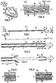
- a probe S is proposed, the extreme part 1 of which is intended to be mechanically and electrically associated, in a known manner, by two connections 3,4 to a stimulator P, and respectively to the ventricle and the cardiac atrium. by two electrical and mechanical connections 5,6, one set back 5, the other terminal 6, and located at its opposite extreme part 2.
- the tensioned probe S is rectilinear, has an axis XX, and has a substantially at least pseudo-cylindrical shape of revolution around the axis XX.
- the S probe is flexible for be able to be adapted to the specific path between the stimulator P and the heart C. As a whole and subject to what is explained in detail later, it is substantially inextensible.
- the probe S comprises two electrical conductors 7, 8 forming a one-piece assembly, that is to say non-separable, associated with one another by means allowing their axial sliding, one with respect to the other, along the XX axis.
- the two conductors 7, 8 correspond respectively to the cardiac connection and the terminal cardiac connection 6 set back 5.
- the cardiac connections 5, 6 are spaced from each other along the axis XX of the probe S, by a distance d, which is variable when the conductors 7, 8 are displaced relative to the other, the connection 6 constituting strictly speaking the corresponding free end of the probe S, while the connection 5 is set back, at the rear, from the connection 6.
- the cardiac connections 5, 6 are situated respectively at the free ends of the conductors 7, 8, on the side of the end portion 2.
- the conductor 8 By sliding the conductor 8 for example, relative to the conductor 7, in the direction of the arrow F 1 , directed from the end 2 of the probe towards its end 1, the distance d between the cardiac connections 5, 6 is varied in this case.
- One of the conductors, preferably the conductor 8, has slack in it. its end portion 30 intended to be associated with the stimulator P, to allow relative sliding.
- the probe S comprises unidirectional blocking means 10 of the conductor 8 relative to the conductor 7.
- the blocking means 6 prevent the conductor 8 from sliding by relative to conductor 7 in the direction opposite to arrow Fl beyond a limit position corresponding to the minimum value of d.
- the unidirectional locking means 10 are preferably located at the level of the recessed connection 5.
- the unidirectional locking means 10 are constituted by a ring 10 coaxial with the conductors 7, 8, one end 21 of which is rigidly fixed to the conductor 7 and the opposite end 22 of which faces the connection 5, abuts against a setback ring 23 of conductor 8, in the immediate vicinity of its free end.
- the cardiac connections 5, 6 are preferably constituted by a plurality of fibers respectively 9, 9 'electrically conductive, constituting the end portions of fibers forming the respective conductors, which can be anchored in the heart muscle, diverging from the axis XX of the probe S, and forming a sort of feather duster 24, 25, elastically deformable.
- the fibers take this feather duster shape in the absence of external action.
- the cardiac zone which is in contact with the end of the fibers is determined by the intersection of this cardiac surface with the envelope of fibers.
- the fibers are located in a cone of axis XX whose large base is directed towards the free end of the fibers.
- the intersection surface between the cardiac surface and the envelope of the fibers is therefore greater than that which would be obtained if the fibers were parallel to the axis XX, therefore inside a cylinder.
- the anchoring of fibers in the heart muscle is thus improved.
- the fibers 9.9 ′ may for example be carbon fibers.
- the probe S comprises means 26 for temporarily erasing the feather duster 24, 25 from fibers from at least one cardiac connection 5,6 during its installation, preferably the connection 5 recessed.
- the erasing means 26 of the fibers 9 are constituted by the unidirectional blocking means 10.of the conductor 8 relative to the conductor 7.
- the erasing means are therefore constituted by the ring 10 enclosing the feather duster24 of fibers.
- the ring 10 in addition to its end part 21 for fixing to the conductor 7, directed towards the connection 6, and its end part 22 for abutment against the drop 23 of the conductor 8, has a lateral part 27 for holding the feather duster 24 and a middle part 28 for frontly blocking the fibers 9-of the feather duster 24.
- the lateral part 27 and the conductor 7 are coaxial, pseudo-cylindrical, and define an annular space 29 for erasing the feather duster 24.
- the erasing means 26 are therefore integrated into remains at the probe and form an integral part of it. They are not external means.
- the erasing means 26 are only active when the probe is put in place, the two conductors 7, 8 having a particular relative position, the withdrawing cardiac connection 5 being the closest to the cardiac connection 6, therefore close from the free end 11 of the probe S, the distance d being minimum.
- the erasing means are passive and the fibers 9 are released from the ring 10, to form the feather duster 24.
- the means of axial sliding of the two conductors 7, 8 are two tubes, or sheaths, nested, movable with respect to each other, a radial space or clearance 12 being formed between the tubes . This space allows the axial sliding of the conductors 7, 8.
- the internal conductor 7 is of substantially cylindrical shape, of axis XX and formed of an electrically conductive wire 13 embedded in an insulating sheath 14.
- the conductive wire 13 consists of a plurality of fibers .15 of an electrically conductive material, preferably carbon fibers.
- the insulating sheath 14 is for example made of polyethylene-1ene.
- the electrically conductive wire 13 can be placed in an external insulating sheath 14, also for example, made of polyethylene.
- the external conductor 8 is constituted by an external conductive wire 17 embedded in an insulating external sheath 16, coaxial with the sheath 14 of the internal conductor 7.
- This external electricity conductive wire 17 can consist for example of a plurality of electrically conductive fibers, namely carbon fibers.
- a space or clearance 12 is provided, as mentioned above, to allow the two conductors 7, 8 to slide.
- the external conductor 8 is constituted by a spiral conductive wire 19 which is wound helically around the insulating sheath 14 and comprised between the latter and a coaxial external sheath 16. Between the turns of the spiral wire 19 and the sheath insulating 14, there is an annular space 12 or clearance which allows the sliding of the conductor 8 relative to the conductor 7. Thus, the turns of the wire 19 do not tighten the sheath 14.
- the internal and external sheaths are movable one with respect to the other, freely or with gentle friction thanks to the clearance 12 which is formed between them.
- the procedure is as follows: the free end 11 of the probe S is inserted in a vein according to arrow F 2 , directed in the opposite direction to arrow F 1 , preferably located at the base of the neck.
- the means for erasing preferably the feather duster 24 are then active and the fibers 9 are erased.
- the two conductors 7 and 8 are not movable relative to each other, the unidirectional blocking means 26 of the conductor 8 relative to the conductor 7 being active, the end portion 22 of these means abutting against the setback 23 of conductor 8, as explained above.
- the free end 11 of the probe S is introduced into the ventricle 20, passing through the atrium 18.
- the cardiac connection 6 is then released. This is fixed in the ventricle 20.
- the two internal and external conductors respectively 7.8 have been moved simultaneously and there has been no relative sliding of relative to each other.
- an axial displacement of the external conductor 8 is carried out in the direction of the arrow F 1 ′ .
- the erasing means 26 of the fibers 9 are then inactive and these are released. As they are elastically deformable, they naturally deviate from the axis XX to take the form of a feather duster 24. Finally, when the fibers are at the optimal point of ear collection, they will be fixed in the atrium 18 .
- the distance d between the atrial collection point and the ventricular collection point varying according to the patients, it suffices to adapt the probe, to more or less slide the external conductor 8 relative to the internal conductor 7 in the direction of the arrow F 1 directed from the extreme part 2 of the probe associated with the heart muscle towards the extreme part 1.
Landscapes
- Health & Medical Sciences (AREA)
- Heart & Thoracic Surgery (AREA)
- Cardiology (AREA)
- Life Sciences & Earth Sciences (AREA)
- Public Health (AREA)
- Engineering & Computer Science (AREA)
- Biomedical Technology (AREA)
- Nuclear Medicine, Radiotherapy & Molecular Imaging (AREA)
- Radiology & Medical Imaging (AREA)
- Animal Behavior & Ethology (AREA)
- General Health & Medical Sciences (AREA)
- Veterinary Medicine (AREA)
- Physiology (AREA)
- Biophysics (AREA)
- Vascular Medicine (AREA)
- Electrotherapy Devices (AREA)
- Measuring Leads Or Probes (AREA)
Priority Applications (1)
| Application Number | Priority Date | Filing Date | Title |
|---|---|---|---|
| AT82401202T ATE29967T1 (de) | 1981-07-31 | 1982-06-29 | Koaxiale schiebesonde fuer herzstimulator. |
Applications Claiming Priority (2)
| Application Number | Priority Date | Filing Date | Title |
|---|---|---|---|
| FR8114944A FR2510390B1 (fr) | 1981-07-31 | 1981-07-31 | Sonde coaxiale coulissante pour stimulateur cardiaque |
| FR8114944 | 1981-07-31 |
Publications (3)
| Publication Number | Publication Date |
|---|---|
| EP0071495A2 true EP0071495A2 (de) | 1983-02-09 |
| EP0071495A3 EP0071495A3 (en) | 1984-09-05 |
| EP0071495B1 EP0071495B1 (de) | 1987-09-30 |
Family
ID=9261056
Family Applications (1)
| Application Number | Title | Priority Date | Filing Date |
|---|---|---|---|
| EP82401202A Expired EP0071495B1 (de) | 1981-07-31 | 1982-06-29 | Koaxiale Schiebesonde für Herzstimulator |
Country Status (5)
| Country | Link |
|---|---|
| US (1) | US4574814A (de) |
| EP (1) | EP0071495B1 (de) |
| AT (1) | ATE29967T1 (de) |
| DE (1) | DE3277400D1 (de) |
| FR (1) | FR2510390B1 (de) |
Cited By (3)
| Publication number | Priority date | Publication date | Assignee | Title |
|---|---|---|---|---|
| EP0159540A1 (de) * | 1984-04-06 | 1985-10-30 | Osypka, Peter, Dr. Ing. | Chirurgische Elektrode |
| EP0479435A3 (en) * | 1990-10-01 | 1992-06-24 | Ventritex, Inc. | Multiple electrode deployable lead |
| WO1998048887A1 (en) * | 1997-04-29 | 1998-11-05 | Medtronic, Inc. | Intracardiac defibrillation system |
Families Citing this family (34)
| Publication number | Priority date | Publication date | Assignee | Title |
|---|---|---|---|---|
| DE3445102C1 (de) * | 1984-12-11 | 1986-01-30 | Dr.-Ing. P. Osypka GmbH Medizinelektronik, 7880 Grenzach-Wyhlen | Elektrode mit einem Stecker fuer einen aeusseren Herzschrittmacher oder EKG-Monitor |
| US4664120A (en) * | 1986-01-22 | 1987-05-12 | Cordis Corporation | Adjustable isodiametric atrial-ventricular pervenous lead |
| DE3914662A1 (de) * | 1989-05-03 | 1990-11-08 | Alt Eckhard | Vorrichtung zum uebertragen elektrischer signale zwischen einem implantierbaren medizinischen geraet und elektrisch erregbarem menschlichen gewebe |
| US5411527A (en) * | 1989-05-03 | 1995-05-02 | Intermedics, Inc. | Difibrillation electrodes and implantation |
| US5433729A (en) * | 1991-04-12 | 1995-07-18 | Incontrol, Inc. | Atrial defibrillator, lead systems, and method |
| US5443559A (en) * | 1992-10-30 | 1995-08-22 | The University Of British Columbia | Brush-tip electrode |
| US5299572A (en) * | 1992-10-30 | 1994-04-05 | University Of British Columbia | Biological electrode array |
| US5995871A (en) * | 1997-10-29 | 1999-11-30 | Uab Research Foundation | System and method for cardioversion using scan stimulation |
| US5897585A (en) * | 1997-12-18 | 1999-04-27 | Medtronic, Inc. | Stretchable pacing lead |
| US6705999B2 (en) | 2001-03-30 | 2004-03-16 | Guidant Corporation | Method and apparatus for determining the coronary sinus vein branch accessed by a coronary sinus lead |
| US6711443B2 (en) * | 2001-07-25 | 2004-03-23 | Oscor Inc. | Implantable coronary sinus lead and method of implant |
| US6980866B2 (en) * | 2001-12-05 | 2005-12-27 | Cardiac Pacemakers, Inc. | Apparatus for sensing cardiac contractile function |
| US8229574B2 (en) * | 2003-02-21 | 2012-07-24 | Cochlear Limited | Telescopic electrode array |
| US20090259280A1 (en) * | 2007-10-15 | 2009-10-15 | Kevin Wilkin | Electrical stimulation lead with bioerodible anchors and anchor straps |
| US20090210040A1 (en) * | 2008-02-19 | 2009-08-20 | Ochoa Francisco | Variable length medical electrical stimulation lead |
| US20090281409A1 (en) * | 2008-05-06 | 2009-11-12 | Jeryle Walter | Reinforced medical device |
| US11058880B2 (en) | 2018-03-23 | 2021-07-13 | Medtronic, Inc. | VFA cardiac therapy for tachycardia |
| JP2021518192A (ja) | 2018-03-23 | 2021-08-02 | メドトロニック,インコーポレイテッド | VfA心臓再同期治療 |
| EP3768369A1 (de) | 2018-03-23 | 2021-01-27 | Medtronic, Inc. | Av-synchrone vfa-herztherapie |
| EP3856331A1 (de) | 2018-09-26 | 2021-08-04 | Medtronic, Inc. | Erfassung in der ventrikel-aus-atrium-herztherapie |
| US11951313B2 (en) | 2018-11-17 | 2024-04-09 | Medtronic, Inc. | VFA delivery systems and methods |
| EP3897816B1 (de) | 2018-12-21 | 2024-03-27 | Medtronic, Inc. | Freisetzungssysteme für linksventrikuläre stimulation |
| US11679265B2 (en) | 2019-02-14 | 2023-06-20 | Medtronic, Inc. | Lead-in-lead systems and methods for cardiac therapy |
| US11697025B2 (en) | 2019-03-29 | 2023-07-11 | Medtronic, Inc. | Cardiac conduction system capture |
| US11213676B2 (en) | 2019-04-01 | 2022-01-04 | Medtronic, Inc. | Delivery systems for VfA cardiac therapy |
| US11712188B2 (en) | 2019-05-07 | 2023-08-01 | Medtronic, Inc. | Posterior left bundle branch engagement |
| US11065461B2 (en) | 2019-07-08 | 2021-07-20 | Bioness Inc. | Implantable power adapter |
| US11305127B2 (en) | 2019-08-26 | 2022-04-19 | Medtronic Inc. | VfA delivery and implant region detection |
| US11813466B2 (en) | 2020-01-27 | 2023-11-14 | Medtronic, Inc. | Atrioventricular nodal stimulation |
| US12543992B2 (en) | 2020-03-30 | 2026-02-10 | Medtronic, Inc. | Pacing efficacy determination using a representative morphology of external cardiac signals |
| US11911168B2 (en) | 2020-04-03 | 2024-02-27 | Medtronic, Inc. | Cardiac conduction system therapy benefit determination |
| US12605103B2 (en) | 2020-05-21 | 2026-04-21 | Medtronic, Inc. | QRS detection and bracketing |
| US11813464B2 (en) | 2020-07-31 | 2023-11-14 | Medtronic, Inc. | Cardiac conduction system evaluation |
| US12465770B2 (en) | 2020-07-31 | 2025-11-11 | Medtronic, Inc. | Coronary sinus conduction system pacing and delivery |
Family Cites Families (10)
| Publication number | Priority date | Publication date | Assignee | Title |
|---|---|---|---|---|
| US3769984A (en) * | 1971-03-11 | 1973-11-06 | Sherwood Medical Ind Inc | Pacing catheter with frictional fit lead attachment |
| US3865118A (en) * | 1973-12-27 | 1975-02-11 | Univ California | Transvenous coaxial catheter |
| US3949757A (en) * | 1974-05-13 | 1976-04-13 | Sabel George H | Catheter for atrio-ventricular pacemaker |
| DE2605590A1 (de) * | 1976-02-12 | 1977-08-18 | Heinz Dr Med Praeuer | Herzschrittmacherelektrode |
| EP0009732A1 (de) * | 1978-10-06 | 1980-04-16 | Precimed S.A. | Katheter für Herzschrittmacher |
| FR2446001A1 (fr) * | 1979-01-03 | 1980-08-01 | Cardiofrance Co | Conducteur electrique pour stimulateur cardiaque |
| US4271847A (en) * | 1979-06-28 | 1981-06-09 | Medtronic, Inc. | Temporary adjustable bipolar lead |
| US4332259A (en) * | 1979-09-19 | 1982-06-01 | Mccorkle Jr Charles E | Intravenous channel cardiac electrode and lead assembly and method |
| US4289144A (en) * | 1980-01-10 | 1981-09-15 | Medtronic, Inc. | A-V Sidearm lead |
| US4327747A (en) * | 1980-09-22 | 1982-05-04 | Cordis Corporation | Terminal assembly for a carbon fiber implantable lead |
-
1981
- 1981-07-31 FR FR8114944A patent/FR2510390B1/fr not_active Expired
-
1982
- 1982-06-29 EP EP82401202A patent/EP0071495B1/de not_active Expired
- 1982-06-29 AT AT82401202T patent/ATE29967T1/de not_active IP Right Cessation
- 1982-06-29 DE DE8282401202T patent/DE3277400D1/de not_active Expired
- 1982-07-08 US US06/396,397 patent/US4574814A/en not_active Expired - Fee Related
Cited By (4)
| Publication number | Priority date | Publication date | Assignee | Title |
|---|---|---|---|---|
| EP0159540A1 (de) * | 1984-04-06 | 1985-10-30 | Osypka, Peter, Dr. Ing. | Chirurgische Elektrode |
| EP0479435A3 (en) * | 1990-10-01 | 1992-06-24 | Ventritex, Inc. | Multiple electrode deployable lead |
| US5282845A (en) * | 1990-10-01 | 1994-02-01 | Ventritex, Inc. | Multiple electrode deployable lead |
| WO1998048887A1 (en) * | 1997-04-29 | 1998-11-05 | Medtronic, Inc. | Intracardiac defibrillation system |
Also Published As
| Publication number | Publication date |
|---|---|
| FR2510390A1 (fr) | 1983-02-04 |
| DE3277400D1 (en) | 1987-11-05 |
| EP0071495A3 (en) | 1984-09-05 |
| FR2510390B1 (fr) | 1986-06-06 |
| EP0071495B1 (de) | 1987-09-30 |
| US4574814A (en) | 1986-03-11 |
| ATE29967T1 (de) | 1987-10-15 |
Similar Documents
| Publication | Publication Date | Title |
|---|---|---|
| EP0071495B1 (de) | Koaxiale Schiebesonde für Herzstimulator | |
| EP3173126B1 (de) | Implantierbare kapsel, insbesondere autonome kapsel zur stimulation der herzfunktion, und entsprechendes montageverfahren | |
| EP0568463B1 (de) | Sonde für Herzschrittmacher | |
| EP2246091B1 (de) | Intrakardialer Sensor zur Stimulation oder Defibrillation mit zurückziehbarer Schraube | |
| FR2659240A1 (fr) | Systeme d'electrode epidurale appelee a etre introduite dans l'espace epidural. | |
| FR2786701A1 (fr) | Systeme a conducteur electrique medical et a dispositif d'introduction, ensemble conducteur pour un tel systeme et son procede de fabrication | |
| EP0614677B1 (de) | Elektrokatheter zur sequentiellen Herzreizung (DDD) mit einer durch den Sinus coronarius eingeführten einzigen Leitung | |
| EP0779080B1 (de) | Stimulationsleitung mit ausfaltbarer Verankerungsvorrichtung für ein medizinisches, implantierbares Gerät, insbesondere für einen Herzschrittmacher | |
| EP2457612B1 (de) | Instrumentarium zum Stimulieren/Defibrillieren des linken Ventrikels auf endokavitärem Weg oder über eine Koronarvene | |
| EP1331021B1 (de) | Einführungsvorrichtung für eine Stimulations- oder Defibrillationsleitung mit einer einschraubbaren Schraubwendel | |
| FR2483786A1 (fr) | Ensemble a une ou plusieurs electrodes destine a etre introduit dans un catheter et a etablir une liaison electrique avec un circuit electronique | |
| FR2465489A1 (fr) | Conducteur de stimulateur cardiaque | |
| EP0296001A1 (de) | Leitende Enden von Elektroden für Herzstimulation | |
| FR2757773A1 (fr) | Sonde pour dispositif medical a implanter dans le coeur humain pour la stimulation et la detection auriculaire et ventriculaire du coeur | |
| FR2575925A1 (fr) | Electrode pour sonde cardiaque de stimulation et de detection | |
| EP3075411B1 (de) | Multielektrodensonde mit multiplex-steuerung, insbesondere zur herzstimulation, und entsprechendes anschlussverfahren | |
| FR2960786A1 (fr) | Outil de guidage pour catheter | |
| EP0430837A1 (de) | Herzschrittmachersonde mit zusätzlichem Stimulationspol | |
| EP1374945B1 (de) | Koronarsonde mit verbesserten Haltemitteln | |
| FR2494118A1 (fr) | Electrode de stimulateur cardiaque | |
| EP1557194B1 (de) | Einstückige Defibrillationssonde | |
| EP1036572B1 (de) | In Koronarvenen implantierbare Leitung zur Stimulation eines linken Herzvorhofs | |
| FR2742995A1 (fr) | Sonde pour dispositif medical implante, notamment pour stimulateur cardiaque | |
| EP0553580A1 (de) | Endokardiale Leitungen mit Verschlussklappen versehen | |
| EP4228739B1 (de) | Set aus einem implantationszubehör und einer implantierbaren flexiblen stimulationssonde |
Legal Events
| Date | Code | Title | Description |
|---|---|---|---|
| PUAI | Public reference made under article 153(3) epc to a published international application that has entered the european phase |
Free format text: ORIGINAL CODE: 0009012 |
|
| AK | Designated contracting states |
Designated state(s): AT BE CH DE GB IT LI LU NL SE |
|
| PUAL | Search report despatched |
Free format text: ORIGINAL CODE: 0009013 |
|
| AK | Designated contracting states |
Designated state(s): AT BE CH DE GB IT LI LU NL SE |
|
| 17P | Request for examination filed |
Effective date: 19850504 |
|
| 17Q | First examination report despatched |
Effective date: 19860523 |
|
| RAP1 | Party data changed (applicant data changed or rights of an application transferred) |
Owner name: CARDIOFRANCE- COMPAGNIE FRANCAISE D'ELECTROCARDIOL |
|
| GRAA | (expected) grant |
Free format text: ORIGINAL CODE: 0009210 |
|
| ITF | It: translation for a ep patent filed | ||
| AK | Designated contracting states |
Kind code of ref document: B1 Designated state(s): AT BE CH DE GB IT LI LU NL SE |
|
| PG25 | Lapsed in a contracting state [announced via postgrant information from national office to epo] |
Ref country code: SE Effective date: 19870930 Ref country code: AT Effective date: 19870930 |
|
| REF | Corresponds to: |
Ref document number: 29967 Country of ref document: AT Date of ref document: 19871015 Kind code of ref document: T |
|
| REF | Corresponds to: |
Ref document number: 3277400 Country of ref document: DE Date of ref document: 19871105 |
|
| GBT | Gb: translation of ep patent filed (gb section 77(6)(a)/1977) | ||
| PG25 | Lapsed in a contracting state [announced via postgrant information from national office to epo] |
Ref country code: LU Free format text: LAPSE BECAUSE OF NON-PAYMENT OF DUE FEES Effective date: 19880630 |
|
| PLBI | Opposition filed |
Free format text: ORIGINAL CODE: 0009260 |
|
| PLAB | Opposition data, opponent's data or that of the opponent's representative modified |
Free format text: ORIGINAL CODE: 0009299OPPO |
|
| 26 | Opposition filed |
Opponent name: BIOTRONIK MESS- UND THERAPIEGERAETE GMBH & CO IN Effective date: 19880627 |
|
| R26 | Opposition filed (corrected) |
Opponent name: BIOTRONIK MESS- UND THERAPIEGERAETE GMBH & CO IN Effective date: 19880818 |
|
| NLR1 | Nl: opposition has been filed with the epo |
Opponent name: BIOTRONIK MESS- UND THERAPIEGERAETE GMBH & CO |
|
| PGFP | Annual fee paid to national office [announced via postgrant information from national office to epo] |
Ref country code: GB Payment date: 19900619 Year of fee payment: 9 |
|
| PGFP | Annual fee paid to national office [announced via postgrant information from national office to epo] |
Ref country code: LU Payment date: 19900621 Year of fee payment: 9 |
|
| PGFP | Annual fee paid to national office [announced via postgrant information from national office to epo] |
Ref country code: NL Payment date: 19900630 Year of fee payment: 9 |
|
| PGFP | Annual fee paid to national office [announced via postgrant information from national office to epo] |
Ref country code: CH Payment date: 19900726 Year of fee payment: 9 |
|
| PLBN | Opposition rejected |
Free format text: ORIGINAL CODE: 0009273 |
|
| STAA | Information on the status of an ep patent application or granted ep patent |
Free format text: STATUS: OPPOSITION REJECTED |
|
| 27O | Opposition rejected |
Effective date: 19900907 |
|
| NLR2 | Nl: decision of opposition | ||
| PG25 | Lapsed in a contracting state [announced via postgrant information from national office to epo] |
Ref country code: GB Effective date: 19910629 |
|
| ITTA | It: last paid annual fee | ||
| PG25 | Lapsed in a contracting state [announced via postgrant information from national office to epo] |
Ref country code: LI Effective date: 19910630 Ref country code: CH Effective date: 19910630 |
|
| PGFP | Annual fee paid to national office [announced via postgrant information from national office to epo] |
Ref country code: DE Payment date: 19910730 Year of fee payment: 10 |
|
| PGFP | Annual fee paid to national office [announced via postgrant information from national office to epo] |
Ref country code: BE Payment date: 19910802 Year of fee payment: 10 |
|
| PG25 | Lapsed in a contracting state [announced via postgrant information from national office to epo] |
Ref country code: NL Effective date: 19920101 |
|
| NLV4 | Nl: lapsed or anulled due to non-payment of the annual fee | ||
| GBPC | Gb: european patent ceased through non-payment of renewal fee | ||
| REG | Reference to a national code |
Ref country code: CH Ref legal event code: PL |
|
| PG25 | Lapsed in a contracting state [announced via postgrant information from national office to epo] |
Ref country code: BE Effective date: 19920630 |
|
| BERE | Be: lapsed |
Owner name: CARDIOFRANCE- CIE FRANCAISE D'ELECTROCARDIOLOGIE Effective date: 19920630 |
|
| PG25 | Lapsed in a contracting state [announced via postgrant information from national office to epo] |
Ref country code: DE Effective date: 19930302 |
|
| APAH | Appeal reference modified |
Free format text: ORIGINAL CODE: EPIDOSCREFNO |