EP0071529A1 - Groupe moto-pompe, notamment pour dispositif d'assistance de direction d'un véhicule automobile - Google Patents
Groupe moto-pompe, notamment pour dispositif d'assistance de direction d'un véhicule automobile Download PDFInfo
- Publication number
- EP0071529A1 EP0071529A1 EP82401376A EP82401376A EP0071529A1 EP 0071529 A1 EP0071529 A1 EP 0071529A1 EP 82401376 A EP82401376 A EP 82401376A EP 82401376 A EP82401376 A EP 82401376A EP 0071529 A1 EP0071529 A1 EP 0071529A1
- Authority
- EP
- European Patent Office
- Prior art keywords
- motor
- pump
- pump unit
- safety valve
- assembly part
- Prior art date
- Legal status (The legal status is an assumption and is not a legal conclusion. Google has not performed a legal analysis and makes no representation as to the accuracy of the status listed.)
- Granted
Links
- 238000007789 sealing Methods 0.000 claims abstract description 5
- 230000005540 biological transmission Effects 0.000 claims abstract description 3
- 230000002093 peripheral effect Effects 0.000 claims abstract description 3
- 238000011144 upstream manufacturing Methods 0.000 claims abstract description 3
- 230000000903 blocking effect Effects 0.000 claims description 5
- 238000000465 moulding Methods 0.000 claims description 4
- 230000000717 retained effect Effects 0.000 claims description 2
- 238000004891 communication Methods 0.000 description 3
- 238000010276 construction Methods 0.000 description 3
- 238000003754 machining Methods 0.000 description 2
- 229910000842 Zamak Inorganic materials 0.000 description 1
- 230000007547 defect Effects 0.000 description 1
- 239000012530 fluid Substances 0.000 description 1
- 238000004519 manufacturing process Methods 0.000 description 1
- 238000000034 method Methods 0.000 description 1
- 230000000149 penetrating effect Effects 0.000 description 1
- 238000005086 pumping Methods 0.000 description 1
- 230000002787 reinforcement Effects 0.000 description 1
- 230000002747 voluntary effect Effects 0.000 description 1
Images

Classifications
-
- F—MECHANICAL ENGINEERING; LIGHTING; HEATING; WEAPONS; BLASTING
- F04—POSITIVE - DISPLACEMENT MACHINES FOR LIQUIDS; PUMPS FOR LIQUIDS OR ELASTIC FLUIDS
- F04C—ROTARY-PISTON, OR OSCILLATING-PISTON, POSITIVE-DISPLACEMENT MACHINES FOR LIQUIDS; ROTARY-PISTON, OR OSCILLATING-PISTON, POSITIVE-DISPLACEMENT PUMPS
- F04C14/00—Control of, monitoring of, or safety arrangements for, machines, pumps or pumping installations
- F04C14/24—Control of, monitoring of, or safety arrangements for, machines, pumps or pumping installations characterised by using valves controlling pressure or flow rate, e.g. discharge valves or unloading valves
-
- F—MECHANICAL ENGINEERING; LIGHTING; HEATING; WEAPONS; BLASTING
- F04—POSITIVE - DISPLACEMENT MACHINES FOR LIQUIDS; PUMPS FOR LIQUIDS OR ELASTIC FLUIDS
- F04C—ROTARY-PISTON, OR OSCILLATING-PISTON, POSITIVE-DISPLACEMENT MACHINES FOR LIQUIDS; ROTARY-PISTON, OR OSCILLATING-PISTON, POSITIVE-DISPLACEMENT PUMPS
- F04C15/00—Component parts, details or accessories of machines, pumps or pumping installations, not provided for in groups F04C2/00 - F04C14/00
Definitions
- the present invention relates to motor-pump groups composed of a hydraulic pump and an electric drive motor assembled so as to form a mono-block unit. More particularly, the invention relates to an improved motor-pump group in which the hydraulic pump, preferably of the gear type, is intended to supply the hydraulic circuit of the steering assistance device of a motor vehicle.
- the pipes being intended to establish the various communications between the suction and discharge cavities of the pump and of the control valves which are arranged in this same intermediate part.
- One of the valves constitutes a safety against pressures exceeding a certain predetermined value.
- the object of the invention is to provide a motor-pump unit recalling the known construction of the aforementioned patent, but which can be manufactured at a much lower cost price, while ensuring a perfect seal at the joint plane between the intermediate part. assembly and pump.
- the subject of the invention is therefore a motor-pump group for a steering assistance device of a motor vehicle, this group being composed of a hydraulic pump and an electric DC drive motor assembled from so as to form a unit, in which the assembly between motor and pump is carried out using a single assembly part forming at the same time one of the flanges of the electric motor, a bushing for the transmission of the movement of rotation between motor and pump and the casing of a safety valve, this motor-pump unit being characterized in that the assembly part has a housing for a seal ensuring the seal between the pump cavity and the electric motor, as well as a single machined surface located on the side of the pump, surface in which is made a peripheral groove for a seal forming a seal with the pump housing and in that inside the perimeter defined by the groove are located two orifices communicating respectively on the one hand directly with the chambers suction and discharge of said pump and on the other hand with the upstream and downstream sides of said safety valve.
- the casing of the safety valve communicates through simple orifices with the corresponding chambers of the pump, so that the intermediate assembly part can be manufactured for an inexpensive molding process while sealing is ensured by a seal which is housed in a groove in the end surface on the pump side of this part, a groove with respect to which said orifices are judiciously arranged.
- the group comprises a motor electric drive built autonomously so that the intermediate piece disposed between the motor and the pump does not constitute the flange of this motor. Furthermore, the intermediate piece has no arrangement for mounting a safety valve.
- the group described in FR 2,436,895 comprises an intermediate piece of e assemblag which is a simple flange of the electric motor, but which is not to convey the pumped fluid.
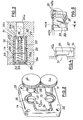
- the motor-pump unit 1 comprises an electric motor 2,, a hydraulic pump 3 as well as an assembly part 4, the assembly forming a monobloc unit.
- the electric motor 2 which will not be described in detail in the present description, can be of any type, but it can advantageously consist of the motor described in the patent application filed on the same day in the name of the Applicant, for : "Electric motor in particular for driving a hydraulic gear pump”. It suffices to note here that this motor comprises an output shaft 5 driven in rotation by a rotor 6 which is rotatably mounted in a stator 7 with permanent magnets itself arranged in a casing 8.
- the hydraulic pump 3 is preferably of the A type.
- gears 9a, 9b (see Fig.2) mounted in a pump housing 10 from which emerges a stud 11 integral in rotation with the gear 9a.
- Motor 2 and pump 3 are assembled using of the assembly part 4 which is in the general form of a circular disc constituting one of the flanges of the motor 2.
- the assembly part is fixed to the casing of the latter by means of crimped lugs 12 penetrating respectively in notches 13 formed at the periphery of the assembly part.
- This comprises a central body 14 whose cross section is adapted to the shape of the pump body and which protrudes on either side of the faces of the disc forming a flange.
- This central body has a passage 15 of generally cylindrical section centered on the axis XX of the shaft 5 of the electric motor 2.
- the passage 15 is stepped and first receives a bearing 16 of the shaft 5, a seal d seal 17, an Oldham seal 18 as well as the pin 11 of the gear 9a.
- the Oldham seal 18 is of known type making it possible to absorb the geometric alignment defects between the shaft 5 of the electric motor, on the one hand, and the equipment formed by the pin 11 and the gear 9a, d 'somewhere else.
- the casing 10 of the pump 3 is attached to the body 14 of the assembly part 4 by means of four screws 19.
- the gear 9b which is rotatably mounted in the casing 10 comprises a cylindrical end piece 20 which is received with play in a cavity 21 whose axis is parallel to the axis XX and which is formed in the body 14.
- the casing 10 of the pump 3 is pressed against a flat end surface 22 of the assembly part 4, this surface being the only element machined with precision on this part.
- a groove 23 is formed in this surface and bypasses the cylindrical passage 15 and the cavity 21.
- a seal 24 disposed in this groove seals the cavity of the pump 3 from the outside.
- the body 14 of the assembly part 4 has also a transverse blind hole 25 (Fig.3) located above the passage 15.
- This hole is stepped and comprises two parts 25a, 25b of diameters increasing from the inside to the outside and separated by a radial shoulder 25c.
- the rear part 25a communicates with an oblong light 26 which opens directly into the cavity of the pump 3 on the delivery side (high pressure), while the front part 25b is in communication with an oblong light 27 which also opens directly in the cavity of the pump, but on the suction side.
- a sleeve 28 of circular section is mounted by screwing in the blind hole 25 and stopped against the radial shoulder 25c. It comprises a radial end neck 29 which forms a seat for a needle 30 of a safety valve 31, the central hole delimited by the neck 29 establishing communication between the part 25a (discharge side of the pump- and the delimited chamber by the sleeve 28 which, through orifices 32 is connected to the part 25b, when the needle is lifted from its seat.
- This needle is kept pressed on its seat thanks to a calibrated spring 33 which is supported on a plug 34 retained in an enlarged front part 28a of the sleeve 28 while being tightened against a radial shoulder 28b formed therein.
- the plug 34 is held in place by a circular plate 35 which is itself blocked by an annular rim crimped 28c of the sleeve 28.
- the latter is in turn blocked by a flange 36 of the body 14 crimped against the annular rim 28c.
- Figs. 4 and 5 representing an alternative mounting of the safety valve 31.
- the body 14 of the connecting piece 4 has a cavity 37 which opens to the outside by a rectangular opening 38 through which the valve 31 can to be placed.
- a blocking wedge 39 is inserted into the cavity 37 is held in position by crimped lugs 40a and 40b which are molded with the body 14.
- the assembly part also comprises two fixing plates 41a and 41b which have come from molding and which extend outwards from two reinforcement wings 42 extending between the body 14 and the periphery of the assembly part.
- Each sole 41a, 41b has a housing 43 for a screw 44, two opposite walls of this housing being formed by deformable lugs 45 make it possible to make the screw 44 captive while maintaining it! against any rotation.
- the rod of the screw passes through the bottom of the housing 43.
- the screws 44 it is possible to provide in the housings 43 nuts of the same dimensions as the heads of these screws.
- the assembly part 4 can thus be produced entirely by molding. It is preferable to use for this part the die-cast Zamac, only the face 22 contiguous to the pump requiring precise machining.
- the Oldham seal 18 is lubricated in operation by the oil transported by the pump 3 which fills the bore 15 thanks to a voluntary leak from this pump.
Landscapes
- Engineering & Computer Science (AREA)
- Mechanical Engineering (AREA)
- General Engineering & Computer Science (AREA)
- Physics & Mathematics (AREA)
- Fluid Mechanics (AREA)
- Details And Applications Of Rotary Liquid Pumps (AREA)
- Rotary Pumps (AREA)
- Details Of Reciprocating Pumps (AREA)
Abstract
Description
- La présente invention est relative aux groupes moto-pompe composée d'une pompe hydraulique et d'un moteur électrique d'entraînement assemblés de façon à former une unité mono-bloc. Plus particulièrement, l'invention vise un groupe moto-pompe perfectionné dans lequel la pompe hydraulique, de préférence du type à engrenages, est destinée à alimenter le circuit hydraulique du dispositif d'assistance de direction d'un véhicule automobile.
- La tendance actuelle dans la construction des véhicules automobiles est d'assurer au conducteur un maximum de confort et de sécurité et les constructeurs cherchent donc à équiper les véhicules (même ceux dits "de bas de gamme") d'équipements permettant d'obtenir ce résultat. Il en est ainsi notamment de la direction à laquelle on tend à adjoindre de plus en plus une assistance permettant au conducteur de manoeuvrer facilement surtout à basse vitesse et à l'arrêt. S'il s'agit de véhicules de "bas de gamme", il est naturellement essentiel que ces équipements supplémentaires n'augmentent pas excessivement le prix de revient du véhicule dans son ensemble et on cherche donc dans toute la mesure du possible d'en réduire les coûts de fabrication. Dans le GB 987 587, on décrit déjà un groupe moto-pompe comprenant une pompe à engrenages ainsi qu'un moteur électrique d'entraînement, ces deux composants étant connectés ensemble par l'intermédiaire d'une pièce d'assemblage qui en ce qui concerne le moteur électrique constitue un flasque de celui-ci supportant un palier de son arbre.
- Dans la pièce intermédiaire est prévu un réseau de canalisations d'une complexité relativement grande, les canalisations étant destinées à établir les diverses communications entre les cavités d'aspiration et de refoulement de la pompe et des clapets de régulation qui sont agencés dans cette même pièce intermédiaire. L'un des clapets constitue une sécurité contre les pressions dépassant une certaine valeur prédéterminée.
- Le réseau des canalisations de la pièce intermédiaire ne peut être réalisée que par usinage ce qui re n d évidemment cette pièce intermédiaire coûteuse et peu compatible avec les exigences évoquées ci-dessus concernant l'industrie automobile. Par ailleurs, cette unité de pompage antérieure est destinée à être immergée dans une bâche d'huile et ne nécessite donc aucune étanchéité au niveau du plan de joint entre la pompe et la pièce intermédiaire.
- L'invention a pour but de fournir un groupe moto-pompe rappelant la construction connue du brevet précité, mais pouvant être fabriqué à un prix de revient bien plus faible, tout en assurant une étanchéité parfaite au niveau du plan de joint entre la pièce intermédiaire d'assemblage et la pompe.
- L'invention a donc pour objet un groupe moto- moto-pompe pour dispositif d'assistance de direction d'un véhicule automobile, ce groupe étant composé d'une pompe hydraulique et d'un moteur électrique d'entraînement à courant continu assemblés de façon à former une unité, dans lequel l'assemblage entre moteur et pompe est réalisé à l'aide d'une pièce d'assemblage unique formant à la fois l'un des flasques du moteur électrique, une traversée pour la transmission du mouvement de rotation entre moteuret pompe et le carter d'un clapet de sécurité, ce groupe moto-pompe étant caractérisé en ce que la pièce d'assemblage présente un logement pour un joint assurant l'étanchéité entre la cavité de la pompe et le moteur électrique, ainsi qu'une unique surface usinée située du côté de la pompe, surface dans laquelle est pratiquée une rainure périphérique pour un joint formant étanchéité avec le carter de la pompe et en ce qu'à l'intérieur du périmètre défini par la rainure sont situées deux orifices communiquant respectivement d'une part directement avec les chambres d'aspiration et de refoulement de ladite pompe et d'autre part avec les côtés amont et aval dudit clapet de sécurité.
- Grâce à ces caractéristiques, le carter du clapet de sécurité communique par de simples orifices avec les chambres correspondantes de la pompe si bien que la pièce intermédiaire d'assemblage peut être fabriquée pour un procédé bon marché de moulage alors que l'étanchéité est assurée par un joint qui est logé dans une rainure de la surface d'extrémité côté pompe de cette pièce, rainure par rapport à laquelle sont judicieusement disposés lesdits orifices.
- Il est a noter que d'autres groupes moto-pompe compacts sont décrits dans l'art antérieur, par exemple, dans les FR 2 242 885 et le FR 2 436 895. Cependant, dans le premier de ces documents le groupe comporte un moteur électrique d'entraînement construit de façon autonome de sorte que la pièce intermédiaire disposée entre le moteur et la pompe ne constitue pas le flasque de ce moteur. Par ailleurs, la pièce intermédiaire ne comporte aucun aménagement pour le montage d'un clapet de sécurité.
- Le groupe décrit dans le FR 2 436 895 comporte une pièce intermédiaire d'assemblagequi est un simple flasque du moteur électrique, mais qui ne sert nullement à véhiculer le fluide pompé.
- L'invention sera décrite ci-après en se référant aux dessins annexés donnés uniquement à titre d'exemple et sur lesquels :
- - la Fig. 1 est une vue en perspective partielle et avec arrachement partiel d'un groupe moto-pompe suivant l'invention;
- - la Fig. 2 est une vue en perspective schématique de la partie d'extrémité, côté pompe, de la pièce d'assemblage du groupe moto-pompe;
- - la Fig. 3 montre une vue à plus grande échelle et en coupe axiale du clapet de sécurité à montage inviolable;
- - la Fig.4 est une vue schématique en coupe d'un autre dispositif utilisé comme bouchon inviolable du clapet de sécurité;
- - la Fig. 5 est une vue en perspective schématique du bouchon de la Fig.4.
- On se réfère tout d'abord à la Fig. 1 sur laquelle on voit que le groupe moto-pompe 1 comporte un moteur électrique 2,,une pompe hydraulique 3 ainsi qu'une pièce d'assemblage 4, l'ensemble formant une unité monobloc. Le moteur électrique 2 qui ne sera pas décrit en détail dans la présente description, peut être d'un type quelconque, mais il peut être constitué avantageusement par le moteur décrit dans la demande de brevet déposée ce même jour au nom de la Demanderesse, pour: "Moteur électrique notamment pour l'entraînement d'une pompe hydraulique à engrenages". Il suffit de noter ici que ce moteur comporte un arbre de sortie 5 entraîné en rotation par un rotor 6 qui est monté en rotation dans un stator 7 à aimants permanents lui-même disposé dans un carter 8.
- La pompe hydraulique 3 est de préférence du type à. engrenages 9a, 9b (voir Fig.2) montée dans un carter de pompe 10 dont émerge un tenon 11 solidaire en rotation de l'engrenage 9a.
- Le moteur 2 et la pompe 3 sont assemblés à l'aide de la pièce d'assemblage 4 qui se présente sous la forme générale d'un disque circulaire constituant l'un des flasques du moteur 2. La pièce d'assemblage est fixée sur le carter de ce dernier au moyen de pattes serties 12 pénétrant respectivement dans des encoches 13 ménagées à la périphérie de la pièce d'assemblage. Celle-ci comporte un corps central 14 dont la section est adaptée à la forme du corps de pompe et qui dépasse de part et d'autre des faces du disque formant flasque. Ce corps central comporte un passage 15 de section générale cylindrique centrée sur l'axe X-X de l'arbre 5 du moteur électrique 2. Le passage 15 est étagé et reçoit tout d'abord un roulement 16 de l'arbre 5, un joint d'étanchéité 17, un joint d'Oldham 18 ainsi que le tenon 11 de l'engrenage 9a. Le joint d'Oldham 18 est de type connu permettant d'absorber les défauts géométriques d'alignement entre l'arbre 5 du moteur électrique, d'une part, et l'équipage constitué par le tourillon 11 et l'engrenage 9a, d'autre part.
- Le carter 10 de la pompe 3 est rapporté sur le corps 14 de la pièce d'assemblage 4 par l'intermédiaire de quatre vis 19. L'engrenage 9b qui est monté à rotation dans le carter 10 comporte un embout cylindrique 20 qui est reçu avec jeu dans une cavité 21 dont l'axe est parallèle à l'axe X-X et qui est ménagé dans le corps 14.
- Le carter 10 de la pompe 3 est appuyé contre une surface plane d'extrémité 22 de la pièce d'assemblage 4, cette surface étant le seul élement usiné avec précision sur cette pièce. Une rainure 23 est ménagée dans cette surface et contourne le passage cylindrique 15 et la cavité 21. Un joint 24 disposé dans cette rainure assure l'étanchéité de la cavité de la pompe 3 vis à vis de l'extérieur.
- Le corps 14 de la pièce d'assemblage 4 présente également un trou borgne transversal 25 (Fig.3) situe au-dessus du passage 15. Ce trou est étagé et comprend deux parties 25a, 25b de diamètres croissant de l'intérieur vers l'extérieur et séparées par un épaulement radial 25c. La partie 25a arrière communique avec une lumière oblongue 26 qui débouche directement dans la cavité de la pompe 3 côté refoulement (haute pression), tandis que la partie avant 25b est en communication avec une lumière oblongue 27 qui débouche également directement dans la cavité de la pompe, mais côté aspiration.
- Un manchon 28 de section circulaire est monté par vissage dans le trou borgne 25 et arrêté contre l'épaulement radial 25c. Il comporte un col radial d'extrémité 29 qui forme siège pour un pointeau 30 d'un clapet de sécurité 31, le trou central délimité par le col 29 établissant une communication entre la partie 25a (côté refoulement de la pompe- et la chambre délimitée par le manchon 28 qui, à travers des orifices 32 est reliée à la partie 25b, lorsque le pointeau est levé de son siège.
- Ce pointeau est maintenu appuyé sur son siège grâce à un ressort taré 33 qui prend appui sur un bouchon 34 retenu dans une partie avant élargie 28a du manchon 28 en étant serré contre un épaulement radial 28b ménagé dans celui-ci. Le bouchon 34 est maintenu en place par une plaquette circulaire 35 elle-même bloquée par un rebord annulaire serti 28c du manchon 28. Celui-ci est à son tour bloqué par une collerette 36 du corps 14 sertie contre le rebord annulaire 28c. On comprend que grâce à cette construction le clapet de sécurité 31 ne peut être démonté que moyennant la destruction de la collerette 36, le bouchon 34 ne pouvant être oté qu'en déformant le rebord annulaire 28c. L'ensemble est donc inviolable et une intervention sur le clapet 31 par des personnes non autorisées n'est pas possible.
- Les Fig. 4 et 5 représentenant une variante de montage du clapet de sécurité 31. Dans ce cas, le corps 14 de la pièce d'assemblage 4 présente une cavité 37 qui débouche sur l'extérieur par une ouverture rectangulaire 38 à travers laquelle le clapet 31 peut être mis en place. Un coin de blocage 39 est inséré dans la cavité 37 est maintenu en position par des pattes serties 40a et 40b venues de moulage avec le corps 14.
- Sur la Fig. l, on voit que la pièce d'assemblage comporté également deux semelles de fixation 41a et 41b qui sont venues de moulage et qui s'étendent vers l'extérieur à partir de deux ailes de renfort 42 s'étendant entre le corps 14 et la périphérie de la pièce d'assemblage.
- Chaque semelle 41a, 41b présente un logement 43 pour une vis 44, deux parois opposées de ce logement étant formées par des pattes déformables 45 permettent de rendre la vis 44 imperdable tout en la maintenant ! contre toute rotation. La tige de la vis passe à travers le fond du logement 43. Bien entendu, au lieu des vis 44, on peut prévoir dans les logements 43 des écrous de même dimensions que les têtes de ces vis.
- La pièce d'assemblage 4 peut ainsi être réalisée entièrement par moulage. Il est préférable d'utiliser pour cette pièce le Zamac moulé sous pression, seule la face 22 contigüe à la pompe nécessitant un usinage précis.
- Le joint d'Oldham 18 est lubrifié en fonctionnement par l'huila véhiculée par la pompe 3 qui remplit l'alésage 15 grâce à une fuite volontaire de cette pompe.
Claims (7)
Applications Claiming Priority (2)
| Application Number | Priority Date | Filing Date | Title |
|---|---|---|---|
| FR8114843 | 1981-07-30 | ||
| FR8114843A FR2510673B1 (fr) | 1981-07-30 | 1981-07-30 | Groupe moto-pompe, notamment pour dispositif d'assistance de direction d'un vehicule automobile |
Publications (2)
| Publication Number | Publication Date |
|---|---|
| EP0071529A1 true EP0071529A1 (fr) | 1983-02-09 |
| EP0071529B1 EP0071529B1 (fr) | 1985-01-23 |
Family
ID=9261012
Family Applications (1)
| Application Number | Title | Priority Date | Filing Date |
|---|---|---|---|
| EP19820401376 Expired EP0071529B1 (fr) | 1981-07-30 | 1982-07-23 | Groupe moto-pompe, notamment pour dispositif d'assistance de direction d'un véhicule automobile |
Country Status (3)
| Country | Link |
|---|---|
| EP (1) | EP0071529B1 (fr) |
| DE (1) | DE3262049D1 (fr) |
| FR (1) | FR2510673B1 (fr) |
Citations (8)
| Publication number | Priority date | Publication date | Assignee | Title |
|---|---|---|---|---|
| US3029740A (en) * | 1956-03-13 | 1962-04-17 | Tuthill Pump Co | Rotary pumps |
| GB987587A (en) * | 1961-01-30 | 1965-03-31 | Charlotte Vogel | Improvements in gear pump assemblies |
| US3801229A (en) * | 1972-07-27 | 1974-04-02 | S Henderson | Combined motor and rotary fluid device |
| FR2238379A5 (fr) * | 1973-07-17 | 1975-02-14 | Bosch Gmbh Robert | |
| FR2242885A5 (fr) * | 1973-09-04 | 1975-03-28 | Cenco Inc | |
| DE2748897A1 (de) * | 1977-11-02 | 1979-05-03 | Suspa Federungstech | Elektromotorisches pumpenaggregat |
| US4181472A (en) * | 1977-12-12 | 1980-01-01 | Parker-Hannifin Corporation | Liquid dispensing windshield washer pump |
| FR2436895A1 (fr) * | 1978-09-25 | 1980-04-18 | Koehring Co | Ensemble de compresseur d'air |
-
1981
- 1981-07-30 FR FR8114843A patent/FR2510673B1/fr not_active Expired
-
1982
- 1982-07-23 DE DE8282401376T patent/DE3262049D1/de not_active Expired
- 1982-07-23 EP EP19820401376 patent/EP0071529B1/fr not_active Expired
Patent Citations (8)
| Publication number | Priority date | Publication date | Assignee | Title |
|---|---|---|---|---|
| US3029740A (en) * | 1956-03-13 | 1962-04-17 | Tuthill Pump Co | Rotary pumps |
| GB987587A (en) * | 1961-01-30 | 1965-03-31 | Charlotte Vogel | Improvements in gear pump assemblies |
| US3801229A (en) * | 1972-07-27 | 1974-04-02 | S Henderson | Combined motor and rotary fluid device |
| FR2238379A5 (fr) * | 1973-07-17 | 1975-02-14 | Bosch Gmbh Robert | |
| FR2242885A5 (fr) * | 1973-09-04 | 1975-03-28 | Cenco Inc | |
| DE2748897A1 (de) * | 1977-11-02 | 1979-05-03 | Suspa Federungstech | Elektromotorisches pumpenaggregat |
| US4181472A (en) * | 1977-12-12 | 1980-01-01 | Parker-Hannifin Corporation | Liquid dispensing windshield washer pump |
| FR2436895A1 (fr) * | 1978-09-25 | 1980-04-18 | Koehring Co | Ensemble de compresseur d'air |
Also Published As
| Publication number | Publication date |
|---|---|
| FR2510673B1 (fr) | 1985-11-15 |
| DE3262049D1 (en) | 1985-03-07 |
| EP0071529B1 (fr) | 1985-01-23 |
| FR2510673A1 (fr) | 1983-02-04 |
Similar Documents
| Publication | Publication Date | Title |
|---|---|---|
| US6325604B1 (en) | Plastic gear pump housing | |
| FR2721978A1 (fr) | Pompe de regeneration a plage de fonctionnement etendue | |
| EP0041267A1 (fr) | Pompe péristaltique | |
| EP0088674A1 (fr) | Groupe électro-hydraulique pour dispositifs d'assistance, en particulier pour véhicules | |
| FR2673900A1 (fr) | Vehicule automobile pourvu d'un ralentisseur hydrodynamique a la sortie d'une boite de vitesses. | |
| EP2910826B1 (fr) | Vanne à boisseau sphérique rotatif et son procédé de fabrication | |
| EP3645320B1 (fr) | Appareil hydraulique ameliore comprenant une conduite pour la circulation d'air | |
| EP3144472B1 (fr) | Agencement d'au moins deux dispositifs de pompes hydrauliques | |
| EP0071529B1 (fr) | Groupe moto-pompe, notamment pour dispositif d'assistance de direction d'un véhicule automobile | |
| FR2772842A1 (fr) | Pompe et dispositif de pompage | |
| EP3992403A1 (fr) | Actionneur electromecanique pour vehicule automobile | |
| FR2629540A1 (fr) | Embrayage a commande hydraulique, notamment pour vehicule automobile | |
| FR3080576A1 (fr) | Agencement hydraulique pour une roue directrice d'un vehicule | |
| FR2726608A1 (fr) | Pompe a vide munie d'un dispositif de demultiplication a engrenages epicycloidal | |
| FR2934333A1 (fr) | Groupe hydraulique pour une unite de pompe electrique | |
| EP0181797B1 (fr) | Distributeur rotatif hydraulique, plus particulièrement pour mécanisme de direction assistée | |
| EP0095415B1 (fr) | Distributeur rotatif hydraulique à rotor en étoile, plus particulièrement pour mécanisme de direction assistée | |
| FR2491171A3 (fr) | Dispositif tournant de pompage capable de supporter un element tournant tout en debitant un liquide ayant des proprietes lubrifiantes | |
| FR2633017A1 (fr) | Pompe pour liquides visqueux, pompe a huile notamment | |
| BE1027453B1 (fr) | Pompe a engrenage | |
| EP0344059B1 (fr) | Dispositif tournant à engrenages pour la circulation d'un liquide | |
| FR2482675A1 (fr) | Turbine a palettes | |
| EP0082027B1 (fr) | Distributeur rotatif hydraulique pour servomécanisme à vérin dissymétrique | |
| FR2748068A1 (fr) | Pompe rotative a palettes | |
| FR2594184A1 (fr) | Pompe a liquide, notamment pompe a eau pour vehicule automobile |
Legal Events
| Date | Code | Title | Description |
|---|---|---|---|
| PUAI | Public reference made under article 153(3) epc to a published international application that has entered the european phase |
Free format text: ORIGINAL CODE: 0009012 |
|
| AK | Designated contracting states |
Designated state(s): DE GB IT |
|
| 17P | Request for examination filed |
Effective date: 19830730 |
|
| ITF | It: translation for a ep patent filed | ||
| GRAA | (expected) grant |
Free format text: ORIGINAL CODE: 0009210 |
|
| AK | Designated contracting states |
Designated state(s): DE GB IT |
|
| REF | Corresponds to: |
Ref document number: 3262049 Country of ref document: DE Date of ref document: 19850307 |
|
| PLBE | No opposition filed within time limit |
Free format text: ORIGINAL CODE: 0009261 |
|
| STAA | Information on the status of an ep patent application or granted ep patent |
Free format text: STATUS: NO OPPOSITION FILED WITHIN TIME LIMIT |
|
| 26N | No opposition filed | ||
| ITPR | It: changes in ownership of a european patent |
Owner name: CAMBIO RAGIONE SOCIALE;ECIA - EQUIPEMENTS ET COMPO |
|
| ITTA | It: last paid annual fee | ||
| PGFP | Annual fee paid to national office [announced via postgrant information from national office to epo] |
Ref country code: DE Payment date: 19940620 Year of fee payment: 13 |
|
| PGFP | Annual fee paid to national office [announced via postgrant information from national office to epo] |
Ref country code: GB Payment date: 19940718 Year of fee payment: 13 |
|
| PG25 | Lapsed in a contracting state [announced via postgrant information from national office to epo] |
Ref country code: GB Effective date: 19950723 |
|
| GBPC | Gb: european patent ceased through non-payment of renewal fee |
Effective date: 19950723 |
|
| PG25 | Lapsed in a contracting state [announced via postgrant information from national office to epo] |
Ref country code: DE Effective date: 19960402 |