EP0071532A2 - Schaustellvorrichtung - Google Patents
Schaustellvorrichtung Download PDFInfo
- Publication number
- EP0071532A2 EP0071532A2 EP82401398A EP82401398A EP0071532A2 EP 0071532 A2 EP0071532 A2 EP 0071532A2 EP 82401398 A EP82401398 A EP 82401398A EP 82401398 A EP82401398 A EP 82401398A EP 0071532 A2 EP0071532 A2 EP 0071532A2
- Authority
- EP
- European Patent Office
- Prior art keywords
- elements
- uprights
- intended
- modular
- horizontal
- Prior art date
- Legal status (The legal status is an assumption and is not a legal conclusion. Google has not performed a legal analysis and makes no representation as to the accuracy of the status listed.)
- Granted
Links
Images

Classifications
-
- A—HUMAN NECESSITIES
- A47—FURNITURE; DOMESTIC ARTICLES OR APPLIANCES; COFFEE MILLS; SPICE MILLS; SUCTION CLEANERS IN GENERAL
- A47F—SPECIAL FURNITURE, FITTINGS, OR ACCESSORIES FOR SHOPS, STOREHOUSES, BARS, RESTAURANTS OR THE LIKE; PAYING COUNTERS
- A47F5/00—Show stands, hangers, or shelves characterised by their constructional features
- A47F5/10—Adjustable or foldable or dismountable display stands
- A47F5/13—Adjustable or foldable or dismountable display stands made of tubes or wire
Definitions
- the present invention relates to structures intended to be used as displays in general, for example as advertising or other media intended for the exhibition or distribution to the public of objects, products or goods in general.
- the object of the invention is to eliminate the drawbacks indicated above and to produce a display which above all has better adaptability to the various requirements of the user, hence greater productivity, and increased possibilities for changing use, satisfying both aesthetic and practical requirements, and which ensures the necessary solid anchoring of the various constituent elements of the entire structural assembly.
- Another object of the invention is to provide a structure which can be easily assembled, disassembled and reassembled, even with a modified arrangement to adapt it to new employment or aesthetic requirements, thus constituting a very advantageous and functional practical solution. and, moreover, clearly economical.
- a modular element comprising a peripheral frame, preferably tubular, consisting of two horizontal and two vertical uprights arranged orthogonally, and superimposed by their connecting ends so as to form the four angles of the frame. peripheral so as to leave free and clear the mouth of their ends.
- These uprights frame as a border a lattice panel, preferably with rectangular or square meshes formed by a series of horizontal bars parallel to each other and suitably spaced, these bars being stiffened by other bars which are perpendicular to the first.
- These horizontal bars are intended to support the various object-holding elements which can be provided in a suitable shape by according to the most varied specific employment requirements and are formed so that they can be simply hooked to said bars and remain secured thereon so as to form a solid anchor.
- the modular element rests on the ground by means of elements serving as a base, coupled by simple coaxial threading by force, the ends of the uprights as well as the ends of these basic elements being provided for this purpose.
- the modular characteristics of the structure according to the invention allow the composition of exhibition surfaces formed by two or more modular elements which are associated and fixed reciprocally to each other by means of junction elements each intended to be interposed and inserted coaxially by force through the corresponding ends of the horizontal or vertical uprights of these modular elements, these connecting elements preferably being engaged by half their length inside each end.
- This allows the application of an easy and fast system for the assembly of several modular elements which can be associated in horizontal development, by coplanar longitudinal flanking with anchoring provided by means of the corresponding horizontal uprights of each module or else in vertical development by overlapping, with coupling by means of the respective vertical uprights, the two arrangements being possible simultaneously as well as two-sided couplings.
- Another characteristic of the invention consists in the fact that it makes it possible to assemble compositions of variable geometry, for example polygonal, in broken line, etc., or of other configurations or combinations according to the fantasy or according to the most variable various employment needs, essentially thanks to particular joining elements which can be combined in groups articulated centrally by one of their ends, so that each element can be put in place in the same direction as the corresponding module with which it is intended to be coupled, however, another end of this element engages by coaxial threading in the respective end of the corresponding horizontal upright.
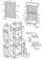
- the invention essentially comprises a modular element 10 consisting (fig. 1) of a tubular peripheral frame formed by two horizontal uprights 11 and two vertical uprights 12.
- the ends of the horizontal uprights 11 are superimposed and solidly united at the ends of the vertical uprights 12 so as to form the four corners of the frame, their mouths (internal surface area of the uprights) being left free and unobstructed.
- This solution was adopted to guarantee the possibilities of being able to receive and insert by coaxial threading various organs intended the possible association between modular elements or other structural components.
- Said uprights 11 and 12 frame as an edge a panel in the form of a trellis .
- the bars 13 serve to support, for example, elements 15 (fig. 2) capable of supporting the goods which it is desired to exhibit and which are intended simply to be placed on the bars 13, the necessary solid anchoring thereon being ensured.
- This basic structure indicated at 16 in fig. 2 consists, in the embodiment shown, of two end support elements 17 securely connected to a tubular frame 18 in the form of an open polygon, the upper ends of this polygon are suitably restricted to be threaded coaxially by force fitting removably inside the lower ends of the uprights 12.
- the invention is not limited to this particular form of foundation 16 as has just been described, but that it can be produced in various forms, for example in the form of an easel, in the form folding, etc., according to job requirements. It is also planned to fix the module 12 directly on a wall, using added elements (not shown) to be applied to each of the four corners of the peripheral frame by coupling them to the ends of the uprights 11.
- An element 19 (FIG. 2) can also be applied above the module 10 so as to form a plate with advertising function.
- This element 19 carries suitably restricted tubular appendages 20 (FIG. 3) intended to couple in the same manner as that which has already been described for operation 16, with the upper ends of the uprights 12.
- the modular characteristics of the element 10 allow the composition of structures formed of two elements 10 or more, always benefiting for their reciprocal association from the coaxial threading, by force, always detachably, of the various components. sants and added components capable of bonding and anchoring.
- FIG. 3 corresponds to a structure composed of eight modules 10 in bifacial position with two back-to-back exposure surfaces of four modules superimposed in two stages.
- the successive longitudinal and coplanar association of the two lower pairs of modules 10 is achieved by the interposition, still by force coaxial engagement, between the corresponding ends of the uprights 11 of junction elements 24, constituted (fig. 4) of a tubular body whose end is suitably restricted (to facilitate insertion) and having at the center of said tubular body, an annular projection 25.
- junction elements 24 constituted (fig. 4) of a tubular body whose end is suitably restricted (to facilitate insertion) and having at the center of said tubular body, an annular projection 25.
- Each of these elements 24 will remain engaged until the middle of its length, inside d 'one of the adjacent ends of the uprights through which it has been interposed, thus achieving a suitable rigid fixing two between the two uprights so that the / module 10 are thus fixed and securely attached to each other, the connection being however removable.
- the structure is completed by assembling at the upper part of two elements 19 forming an advertising plate but intended for applications in a two-sided structure and intended to be coupled to the upper ends of the uprights 12 in the manner already described; an anchor plate 26 with four holes and a plate 27 with two holes are interposed, respectively, in the middle and on the side ( Figures 3 and 4) so as to ensure better stability of the structure.
- an element 28 (FIGS. 3 and 4) carrying four tubular appendages 29 also suitable for restricting themselves, intended to be applied centrally and below, these appendages 29 being coupled to the corresponding ends of the uprights 12.
- the foundation 21, in the example described, has feet 30.
- the display comprises a base frame 31 provided with feet 30, and which carries axially a central axis 32 around which is mounted, so as to be able to rotate, a plate 33 carrying each of its ends, two tubular appendages 34. These are intended to be coupled inside the lower end of the uprights 12 of modules 10, these are assembled in bifacial arrangement and the upper ends of their uprights 12 are mated with the tubular appendages 20 of a plate-shaped element 19.
- a tubular axis 35 is inserted into the upper end of the central tubular axis 32 and an anchor plate 36 is interposed which has two holes at each of its ends and in the center, another hole for the passage of the upper end of the tubular axis 35.
- Another characteristic of the invention is that it makes it possible to obtain an articulated composition with varied geometric configurations at will obtained by assembling two modules 10 or more.
- the side surfaces in all cases consist of an articulated plurality of modules 10 and with each side of the plurimodular side surfaces, with a composition with horizontal or vertical development, depending on the need for use, are achievable with the system assembly according to the invention.
- junction elements 37 can be associated (figs. 6, 7 and 8) in groups of two or more elements, by superposition of their ends 37a, so that the threaded rod of a normal screw 42 can pass through their holes 38, where it is finally locked by means of a nut 43 after having previously predetermined the reciprocal orientation of the elements 37; this orientation is the same as that in which the corresponding modular elements 10 will be arranged.
- These are finally associated with the elements 37 by coaxial threading of the elements 39 inside the end of each of the uprights 11 which thus reciprocally achieve the stable association thanks to the expansion of the elements 39 caused by the actuation of screw 40.
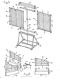
- FIG. 5 represents a structure composed of three modules 10, arranged radially.
- parallelepipedic foundations 41 provided at their ends with two tubular elements 45 which can be threaded inside the ends of the vertical uprights 12 of the module 10 by means of their projecting and restricted ends 45a.
- the form of execution described in fig. 7 shows a structure with a circular arrangement which comprises a cylindrical base 46 which supports, in its center, a group of four cylindrical rods 47 linked together, in a stable manner, by means of a support frame formed by rods 48 which then move apart radially and each carry one of the vertical rods 47 and at their opposite end, a cylindrical peripheral rod 49, fixed to the internal wall of the base 46, each of the rods 49 being designed to carry at its lower part a support leg 30
- the rods 47 and 49 have upper ends 47a and 49a, suitably narrowed so as to be able to be coupled, as said above, by coaxial threading by force, inside the lower ends of the uprights 12 of the modules. 10.
- Plates 51 each of which has the shape of a circular sector with a truncated top, of an extent corresponding to a right angle, are provided, on their curved side, with an edge 52 and, on the opposite side, with another edge 53, which laterally has a short projection 53a.
- These plates 51 are intended to be interposed between the pairs of modules 10; the short projection 53a of the edge 53 is pressed against one of the bars 13, and to ensure the anchoring of the opposite part of the plate 51, two hooks 54 are intended to be hung each on a bar 13 near the external uprights 12 modules 10.
- the anchoring of the plates 51 at the same level makes it possible to obtain a plurality of plates united in coplanar groups.
- Such plates 51 can be placed at will in any position, for example, in several superimposed planes and possibly with level offset between them, according to the requirements of use and individual requirements.
- the modules 10 also fulfill the support function, that of dividing partitions between two adjacent contiguous planes 51, which makes it possible to obtain a plurality of compartments.
- the structure is completed above by an element 55 which forms an advertising plate, and on which are fixed to the internal part, in correspondence with the base 46, four cylindrical rods 56, the lower ends 56a of which are intended to be coupled with the corresponding upper ends of the uprights 12 in a similar manner to what has already been described.
- the present embodiment may also include another arrangement of modules 10 to be assembled in different numbers and with other angular arrangements, for example three modules 10 arranged at 120 °, allowing the use of grate plates and using substantially the same method of assembly.
- each module 10 of affixed elements allows the application to each module 10 of affixed elements, these being largely with modular characteristics and intended to support or contain objects or products in general, intended for exhibition or distribution to the public, the form of these elements being different according to the use for which they are intended.
- These elements are in any case formed so as to be applicable in a simple manner by means of hooks or the like, on the bars 13 of each module 10, thus ensuring, each time, a solid anchoring.
- FIG. 9 Certain embodiments of the wide range of such elements are represented in FIG. 9. On this, we see a folder-carrying element 57, another element with book-holding trays 58, a grid element 15 which is an enlarged view of the elements visible in FIG. 2. Finally, a basket-shaped element 59 and a console element 60 are shown.
- Another advantage of the invention finally consists in the fact that the assembly system of the various elements constituting the structure of the display unit produced essentially by coupling with coaxial threading by force, also allows, consequently, an easy disassembly of the structure itself. even, simply by removing the components themselves thus allowing a new assembly according to the same system.
- the structure of the invention can be produced in any manufacturing method and in any suitable material, preferably, for example, the modules 10 can comprise uprights 11 and 12, in metallic tubular profile or another suitable profile type.
- the basic elements and the object-carrying elements as well as all the other components can be produced in any material suitable for the use for which they are intended.
Landscapes
- Display Racks (AREA)
Priority Applications (1)
| Application Number | Priority Date | Filing Date | Title |
|---|---|---|---|
| AT82401398T ATE74497T1 (de) | 1981-07-28 | 1982-07-27 | Schaustellvorrichtung. |
Applications Claiming Priority (4)
| Application Number | Priority Date | Filing Date | Title |
|---|---|---|---|
| IT21781U IT8100217V0 (it) | 1981-07-28 | 1981-07-28 | Struttura mono o plurimodulare componibile a geometria variabile e sistema d assemblaggio di questa struttura particolarmente adatta per supporti espositori in genere |
| IT30881 | 1981-07-28 | ||
| IT21781U | 1981-07-28 | ||
| IT8100308A IT1212453B (it) | 1981-07-28 | 1981-07-28 | Struttura mono o plurimodulare componibile a geometria variabile e sistema di assemblaggio di questa struttura particolarmente adatta per supporti espositori in genere |
Publications (3)
| Publication Number | Publication Date |
|---|---|
| EP0071532A2 true EP0071532A2 (de) | 1983-02-09 |
| EP0071532A3 EP0071532A3 (en) | 1983-05-04 |
| EP0071532B1 EP0071532B1 (de) | 1992-04-08 |
Family
ID=26324994
Family Applications (1)
| Application Number | Title | Priority Date | Filing Date |
|---|---|---|---|
| EP19820401398 Expired - Lifetime EP0071532B1 (de) | 1981-07-28 | 1982-07-27 | Schaustellvorrichtung |
Country Status (1)
| Country | Link |
|---|---|
| EP (1) | EP0071532B1 (de) |
Cited By (5)
| Publication number | Priority date | Publication date | Assignee | Title |
|---|---|---|---|---|
| FR2596630A1 (fr) * | 1986-04-03 | 1987-10-09 | Caddie Atel Reunis | Dispositif pour le support et la presentation d'objets sur un panneau grillage |
| EP0344130A1 (de) * | 1988-05-27 | 1989-11-29 | Domestik S.R.L. | System zur Konstruktion modularer Möbelstücke |
| US5044505A (en) * | 1988-06-09 | 1991-09-03 | Spratt James V | Equipment storage frame |
| GB2395106A (en) * | 2002-11-14 | 2004-05-19 | Leslie Adrian Alfred Woolard | Modular storage system |
| US20150150387A1 (en) * | 2013-12-02 | 2015-06-04 | Dci Marketing, Inc. | Basket Product Display And Related Methods |
Family Cites Families (5)
| Publication number | Priority date | Publication date | Assignee | Title |
|---|---|---|---|---|
| GB997482A (en) * | 1961-02-16 | 1965-07-07 | William Aitkenhead Ltd | Improvements in or relating to display stands |
| FR1331034A (fr) * | 1962-08-09 | 1963-06-28 | Meurop Sa | Dispositif de rangement |
| FR2196770B1 (de) * | 1972-08-01 | 1976-08-13 | Franc Gerard | |
| DE7417684U (de) * | 1974-05-21 | 1975-12-11 | Orschler Produktion Kg | Gestell insbesondere fuer die zurschaustellung von waren |
| DE2700947C3 (de) * | 1977-01-12 | 1981-08-13 | Wolf 7266 Neuweiler Veyhl | Stellwand, insbesondere für Büro- Ladenräume |
-
1982
- 1982-07-27 EP EP19820401398 patent/EP0071532B1/de not_active Expired - Lifetime
Cited By (7)
| Publication number | Priority date | Publication date | Assignee | Title |
|---|---|---|---|---|
| FR2596630A1 (fr) * | 1986-04-03 | 1987-10-09 | Caddie Atel Reunis | Dispositif pour le support et la presentation d'objets sur un panneau grillage |
| EP0344130A1 (de) * | 1988-05-27 | 1989-11-29 | Domestik S.R.L. | System zur Konstruktion modularer Möbelstücke |
| US5044505A (en) * | 1988-06-09 | 1991-09-03 | Spratt James V | Equipment storage frame |
| GB2395106A (en) * | 2002-11-14 | 2004-05-19 | Leslie Adrian Alfred Woolard | Modular storage system |
| GB2395106B (en) * | 2002-11-14 | 2005-06-29 | Leslie Adrian Alfred Woolard | Modular storage system |
| US20150150387A1 (en) * | 2013-12-02 | 2015-06-04 | Dci Marketing, Inc. | Basket Product Display And Related Methods |
| US9877599B2 (en) * | 2013-12-02 | 2018-01-30 | Retail Space Solutions Llc | Basket product display and related methods |
Also Published As
| Publication number | Publication date |
|---|---|
| EP0071532B1 (de) | 1992-04-08 |
| EP0071532A3 (en) | 1983-05-04 |
Similar Documents
| Publication | Publication Date | Title |
|---|---|---|
| EP0071532A2 (de) | Schaustellvorrichtung | |
| FR2475603A1 (fr) | Necessaire de construction | |
| FR2590144A1 (fr) | Structure de materiel d'exposition realisee a partir d'elements tubulaires assembles les uns aux autres | |
| FR2637057A3 (fr) | Clayette pour armoires frigorifiques | |
| FR3007443A1 (fr) | Dispositif d’amenagement d’abri demontable et/ou pliable | |
| FR2767461A1 (fr) | Dispositif de module pour la realisation d'une gondole d'exposition a la vente d'objets dans un magasin | |
| FR2572633A1 (fr) | Meuble pliant et demontable pouvant servir de podium, de tabouret ou similaire | |
| EP0206988B1 (de) | Drehbarer Schaustand | |
| FR2638345A1 (fr) | Dispositif de rangement et de presentation, notamment pour magasins de detail | |
| EP1386304B1 (de) | Profil und satz von mehreren elementen mit einem oder mehreren solcher profilen | |
| CH721763A2 (fr) | Module de meuble | |
| FR2674735A1 (fr) | Presentoir publicitaire pour produits volumineux, notamment destine aux magasins a grande surface. | |
| FR2647327A1 (fr) | Meuble formant presentoir, du type gondole | |
| CH641338A5 (en) | Display rack for flat objects of rectangular shape | |
| FR3064461B1 (fr) | Meuble demontable, kit et procede correspondants | |
| EP0133142B1 (de) | Anpassbare Stützvorrichtung für eine Lautsprecherbox | |
| FR2753616A1 (fr) | Dispositif de fixation universelle sur structures de presentation d'articles ou de stockage | |
| EP3123900A1 (de) | Möbelstück zum zusammenbau ohne kleber oder schrauben | |
| FR2639527A1 (fr) | Presentoir d'articles, notamment d'articles de parapharmacie | |
| FR2786080A1 (fr) | Dispositif de presentation de produits, autonome et pliant, notamment pour les salons et foires | |
| FR3147940A3 (fr) | Meuble de rangement modulaire | |
| FR2820014A1 (fr) | Installation a au moins deux meubles pouvant etre accoles l'un a l'autre pour la presentation, notamment a la vente, de divers objets ou articles | |
| FR2622417A1 (fr) | Dispositif de securite pour support a langer | |
| EP0543692A1 (de) | Schauanordnung mit einem an vertikalen Kabeln oder Stangen befestigten Pfosten | |
| FR2980964A1 (fr) | Presentoir pour motocycles |
Legal Events
| Date | Code | Title | Description |
|---|---|---|---|
| PUAI | Public reference made under article 153(3) epc to a published international application that has entered the european phase |
Free format text: ORIGINAL CODE: 0009012 |
|
| AK | Designated contracting states |
Designated state(s): AT BE CH DE FR GB LI LU NL SE |
|
| PUAL | Search report despatched |
Free format text: ORIGINAL CODE: 0009013 |
|
| AK | Designated contracting states |
Designated state(s): AT BE CH DE FR GB LI LU NL SE |
|
| 17P | Request for examination filed |
Effective date: 19831026 |
|
| RAP1 | Party data changed (applicant data changed or rights of an application transferred) |
Owner name: QUATTROCCHIO S.R.L. |
|
| GRAA | (expected) grant |
Free format text: ORIGINAL CODE: 0009210 |
|
| AK | Designated contracting states |
Kind code of ref document: B1 Designated state(s): AT BE CH DE FR GB LI LU NL SE |
|
| PG25 | Lapsed in a contracting state [announced via postgrant information from national office to epo] |
Ref country code: SE Effective date: 19920408 Ref country code: NL Effective date: 19920408 Ref country code: GB Effective date: 19920408 Ref country code: AT Effective date: 19920408 |
|
| REF | Corresponds to: |
Ref document number: 74497 Country of ref document: AT Date of ref document: 19920415 Kind code of ref document: T |
|
| REF | Corresponds to: |
Ref document number: 3280398 Country of ref document: DE Date of ref document: 19920514 |
|
| PG25 | Lapsed in a contracting state [announced via postgrant information from national office to epo] |
Ref country code: LU Free format text: LAPSE BECAUSE OF NON-PAYMENT OF DUE FEES Effective date: 19920731 Ref country code: LI Effective date: 19920731 Ref country code: CH Effective date: 19920731 Ref country code: BE Effective date: 19920731 |
|
| NLV1 | Nl: lapsed or annulled due to failure to fulfill the requirements of art. 29p and 29m of the patents act | ||
| GBV | Gb: ep patent (uk) treated as always having been void in accordance with gb section 77(7)/1977 [no translation filed] | ||
| BERE | Be: lapsed |
Owner name: QUATTROCCHIO S.R.L. Effective date: 19920731 |
|
| PLBE | No opposition filed within time limit |
Free format text: ORIGINAL CODE: 0009261 |
|
| STAA | Information on the status of an ep patent application or granted ep patent |
Free format text: STATUS: NO OPPOSITION FILED WITHIN TIME LIMIT |
|
| 26N | No opposition filed | ||
| REG | Reference to a national code |
Ref country code: CH Ref legal event code: PL |
|
| PGFP | Annual fee paid to national office [announced via postgrant information from national office to epo] |
Ref country code: FR Payment date: 19930728 Year of fee payment: 12 |
|
| PGFP | Annual fee paid to national office [announced via postgrant information from national office to epo] |
Ref country code: DE Payment date: 19930928 Year of fee payment: 12 |
|
| PG25 | Lapsed in a contracting state [announced via postgrant information from national office to epo] |
Ref country code: FR Effective date: 19950331 |
|
| PG25 | Lapsed in a contracting state [announced via postgrant information from national office to epo] |
Ref country code: DE Effective date: 19950401 |
|
| REG | Reference to a national code |
Ref country code: FR Ref legal event code: ST |