EP0071573A2 - Tracteur agricole enjambeur à 4 roues directrices - Google Patents
Tracteur agricole enjambeur à 4 roues directrices Download PDFInfo
- Publication number
- EP0071573A2 EP0071573A2 EP82810314A EP82810314A EP0071573A2 EP 0071573 A2 EP0071573 A2 EP 0071573A2 EP 82810314 A EP82810314 A EP 82810314A EP 82810314 A EP82810314 A EP 82810314A EP 0071573 A2 EP0071573 A2 EP 0071573A2
- Authority
- EP
- European Patent Office
- Prior art keywords
- tractor
- section
- implement
- frame
- operator
- Prior art date
- Legal status (The legal status is an assumption and is not a legal conclusion. Google has not performed a legal analysis and makes no representation as to the accuracy of the status listed.)
- Withdrawn
Links
Images



Classifications
-
- B—PERFORMING OPERATIONS; TRANSPORTING
- B62—LAND VEHICLES FOR TRAVELLING OTHERWISE THAN ON RAILS
- B62D—MOTOR VEHICLES; TRAILERS
- B62D49/00—Tractors
- B62D49/06—Tractors adapted for multi-purpose use
- B62D49/0607—Straddle tractors, used for instance above vine stocks, rows of bushes, or the like
-
- B—PERFORMING OPERATIONS; TRANSPORTING
- B62—LAND VEHICLES FOR TRAVELLING OTHERWISE THAN ON RAILS
- B62D—MOTOR VEHICLES; TRAILERS
- B62D7/00—Steering linkage; Stub axles or their mountings
- B62D7/06—Steering linkage; Stub axles or their mountings for individually-pivoted wheels, e.g. on king-pins
- B62D7/14—Steering linkage; Stub axles or their mountings for individually-pivoted wheels, e.g. on king-pins the pivotal axes being situated in more than one plane transverse to the longitudinal centre line of the vehicle, e.g. all-wheel steering
- B62D7/15—Steering linkage; Stub axles or their mountings for individually-pivoted wheels, e.g. on king-pins the pivotal axes being situated in more than one plane transverse to the longitudinal centre line of the vehicle, e.g. all-wheel steering characterised by means varying the ratio between the steering angles of the steered wheels
- B62D7/1509—Steering linkage; Stub axles or their mountings for individually-pivoted wheels, e.g. on king-pins the pivotal axes being situated in more than one plane transverse to the longitudinal centre line of the vehicle, e.g. all-wheel steering characterised by means varying the ratio between the steering angles of the steered wheels with different steering modes, e.g. crab-steering, or steering specially adapted for reversing of the vehicle
-
- B—PERFORMING OPERATIONS; TRANSPORTING
- B60—VEHICLES IN GENERAL
- B60G—VEHICLE SUSPENSION ARRANGEMENTS
- B60G2300/00—Indexing codes relating to the type of vehicle
- B60G2300/40—Variable track or wheelbase vehicles
Definitions
- farm tractors with rear wheel steering, front wheel steering, four wheel crab steering and four wheel coordinated steering.
- tractors with front wheel drive, rear wheel drive and four wheel drive.
- tractors for use in production and harvesting of specialized crops.
- the present invention provides a tractor for use in farming of conventional crops such as oats, corn, soybeans and the like and, more specifically, a tractor for use with interrow cropping equipment that may be operated on slopes or side hills.
- interrow cropping involves the precise planting of second or third crops in narrow gaps between the rows of a standing crop.
- Such a system of interrow cropping is more fully shown and described in my copending application U .S. Serial No. 151,662 filed May 20, 1980 titled "Method of and Apparatus for Interrow Cropping".
- U .S. Serial No. 151,662 filed May 20, 1980 titled "Method of and Apparatus for Interrow Cropping".
- the tractor and the wide interrow implement to accurate ly follow the narrow gaps between the rows; however, if the field is flat , there generally is no problem.
- the difficulty in driving on side hills is that the tractor has a tendency to slip sideways down the hill as it propels itself along the side hill.
- the tractor presents an unbalanced weight which causes the tractor to crab on side hills.
- the tractor wheels In order to traverse a side hill one must turn the tractor wheels at a slight angle to the tractor body to maintain a straight tractor heading.
- the tractor body proceeds along a straight path with the tractor body located at a slight angle with respect to the path of the tractor. This angle is referred to as the crab angle.
- the displacement of the tractor wheels from the straight path produces a displacement in conjunction with the rotation which makes it difficult for a tractor with wide equipment to accurately follow the narrow gaps between the rows of standing crops.
- the gaps between the rows are small, which requires the tool bar and implement to closely follow the gaps between the rows.
- the implements are mounted on the front or rear of the tractor, the problem is compounded.
- the present invention provides a tractor that can more easily follow the narrow gaps between the rows.
- the present invention provides an improvement by providing a tractor with a center mounted implement and four wheel crab steering which coact to minimize the crab angle effect by permitting both front and rear wheels to be turned to minimize the lack of alignment of the tractor body with the tractor path.
- the center mounting of the implement not only reduces the normal displacement that occurs when the tractor body is not in alignment with the path of travel but it also reduces the rotational effects since the translation motion is lessened when the equipment is mounted at the center of the tractor.
- the concept of tractors with front or rear hitch or center mount equipment is known.
- the center mount equipment comprises some of the early farm machinery tractor attachments which had two part cultivators that were attached to both sides of the tractors.
- These prior art tractors did not have high center clearance nor could they handle wide equipment since the operator would usually have to separately attach each part of the cultivator to the side of the tractor.
- These prior art tractors were also limited by use of single axle steering and single axis drive.
- the concept of prior art tractors with high center clearance is also known; however, the prior art high center clearance tractor did not have front and rear steering to permit use in intercropping.
- the invention comprises a tractor having a front mounted engine and a rear mounted cab connected together by telescoping frame members.
- the tractor has sufficiently high center clearance to permit center mounting of the implement.
- the telescoping frame members permit one to extend the tractor body and widen the central implement spacing in the tractor so that the tractor can be driven onto the center mounted implements.
- Four wheel crab steering permits the operator to'better maintain the orientation of the tractor body with respect to path of the tractor.
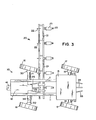
- reference numeral 10 generally designates my high center clearance tractor having a front mounted engine 12 and a rear mounted operator cab 13 connected to each other by a pair of extendible frame members 11. Located between operator cab 13 and engine 12 is a space for a center mount implement 20. Operator cab 13 has side windows 14 and 15 for operator side visibility. Fig. 4 shows a front window 19 that permits an operator to look directly at a center mounted implement 20 which is attached to the center of the tractor with a three point hitch 25. While a three point hitch is shown, my invention could also use single or other multiple point hitches.
- One advantage of the center mounted implement is that the operator can directly see both the gaps between the rows of standing crcps and the implement.
- My tractor 10 also includes a front hitch 41 for use in farm implement applications such as fertilizer applicators, insecticide applicators or knifing in ammonia.
- a three point hitch 35 is located on the rear of tractor 10. Hitch 35 may also be single or multiple and can be used for rear mount implements such as herbicide applications or the like.
- a pair of front wheels 16 and rear wheels 17. are located on opposite ends of the tractor 10 with wheels 16 located forward of implement 20 and wheels 17 located rearward of implement 20.
- Implement 20 comprises a planter having a seed box 23, disc openers 24, a press wheel 25 and a spring tine 22 for loosening the soil in front of disc openers 24.
- the planting units are connected to a tool bar 21, which, as shown in Fig. 3, extends a considerable distance from both sides of tractor 10. While an interrow planter is shown, it is apparent that other equipment could also be mounted on my tractor 10. Typical of other equipment which may be used are cultivators, grain drills, sprayers and fertilizer applicators.
- Figs. 2 and 4 show tractor 10 has a front axle 34 and a pair of steering housings 30 that are connected thereto by steering rods 31 to provide front wheel steering. Similarly, there is'a rear axle 38 with a pair of steering housings 32 with steering rods 33 connected thereto to provide rear wheel steering. Tractor 10 is shown with four wheel crab steering which is illustrated more clearly by the cramped position of the wheels (Fig. 3). By crab steering it is meant that all four wheels can be turned by an operator to control the front and rear of the tractor.
- tractor 10 can be accomplished through a conventional crab steering mechanism which permits turning of the front and rear wheels by an operator located in cab 13.
- Tractor 10 is powered by motor 12 through either a mechanical or hydrostatic drive mechanism.
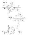
- FIG. 9 shows in exaggerated proportions the effects of slippage.
- Reference numeral 90 denotes the straight travel path it is desired to have tractor 10 follow.
- the central axis of the body of tractor 10 is denoted by reference numeral 92 with reference numeral 93 indicating the direction of forward motion of tractor 91.
- tractor 10 makes an angle e with respect to the travel path 90.
- the implements 94 attached to tractor 10 reduce the spacing between planters located on the tool bar in proportion to the distance from the tractor body. It is this feature of crabbing which is minimized by my tractor.
- Fig. 10 illustrates how my tractor can compensate for slippage by slightly angling both the front and rear wheels.
- axis 92 of tractor body 10 is substantially in alignment with row 90.
- implement bars 94 are maintained perpendicular to travel path 90.
- FIG. 11 schematically illustrates the difference between a rear and center mounted implement.
- Points 0 and N represent the ends of the tractor and point P represents the center of the tractor.
- the implements project perpendicular from the tractor body 10 and the slippage angle is denoted by 0.
- the difference in horizontal displacement between a center mounted implement denoted by lines P S and a rear mounted implement denoted by lines NT is B. From elementary mathematical computation and assuming 9 is small, we can approximate B as Y tangent ⁇ . If e is only 2° and Y is 10 feet, we have an additional displacement of B approximately 4.2 inches between a front and rear mounted implement.
- Fig. 2 shows the front of tractor 10 connected to the rear of tractor 10 through a pair of telescoping frame members 11 which are shown in greater detail in Figs. 5, 6 and 7.
- a telescoping drive mechanism 40 connects to the front and rear of tractor to permit front wheel and rear wheel steering from an operator located in rear mounted cab 13.
- Telescoping drive mechanism also transmits power to the rear wheels if four wheel drive is desired.
- the telescoping frame members comprise a first box member 60 that telescopes outside a second box member 61. As members 61 and 60 slide with respect to one another, they can either expand br contract the tractor body.
- An actual mechanism for telescoping the members is shown as a cog wheel drive 63 which engages a rack of mating teeth 64 on inner telescoping member 61.
- gear 63 Through power supplied to shaft 68 from the tractor or manually one can rotate gear 63 clockwise or counterclockwise to either extend or contract the tractor body.
- the tractor In the extended position the tractor can be driven onto a center mount implement in a zigzag manner as illustrated in schematic form in Fig. 8, i.e., by driving forward, turning all four wheels and then driving backwards and continuing in this zigzag manner one can quickly and efficiently position the tractor in the middle of a center mount implement. This eliminates the need for lifting and moving the center mount implement and the difficulty normally encountered in attaching long implements.
- the oporutor attaches thu implement to three point hitch 25.
- the operator contracts the telescoping members 60 and 61 and fastens the two telescoping members 60 and 61 to each other through bolts and nuts 65 which fit into openings 66 and 67 to thereby hold the front and back of the tractor in the proper position.
- a.mechanical member is shown for telescoping the frame members, it is apparent other mechanisms such as hydraulic members could also be used. From an inspection of the drawing it is apparent that the term high center clearance tractor includes a vehicle in which the top structural portion of the front scetion of a tractor is connected to the top structural portion of the rear section of the tractor with frame members or the like. It should be understood that the operator cab does not constitute a structural support of the tractor but only an area for the convenience of the operator.
Landscapes
- Engineering & Computer Science (AREA)
- Chemical & Material Sciences (AREA)
- Combustion & Propulsion (AREA)
- Transportation (AREA)
- Mechanical Engineering (AREA)
- Agricultural Machines (AREA)
- Guiding Agricultural Machines (AREA)
- Fertilizing (AREA)
- Sowing (AREA)
- Body Structure For Vehicles (AREA)
Applications Claiming Priority (2)
| Application Number | Priority Date | Filing Date | Title |
|---|---|---|---|
| US28624181A | 1981-07-23 | 1981-07-23 | |
| US286241 | 1981-07-23 |
Publications (2)
| Publication Number | Publication Date |
|---|---|
| EP0071573A2 true EP0071573A2 (fr) | 1983-02-09 |
| EP0071573A3 EP0071573A3 (fr) | 1984-02-22 |
Family
ID=23097709
Family Applications (1)
| Application Number | Title | Priority Date | Filing Date |
|---|---|---|---|
| EP82810314A Withdrawn EP0071573A3 (fr) | 1981-07-23 | 1982-07-23 | Tracteur agricole enjambeur à 4 roues directrices |
Country Status (6)
| Country | Link |
|---|---|
| EP (1) | EP0071573A3 (fr) |
| JP (1) | JPS5849559A (fr) |
| AU (1) | AU562658B2 (fr) |
| CA (1) | CA1214729A (fr) |
| MX (1) | MX165093B (fr) |
| NZ (1) | NZ201371A (fr) |
Cited By (5)
| Publication number | Priority date | Publication date | Assignee | Title |
|---|---|---|---|---|
| GB2182005A (en) * | 1985-10-24 | 1987-05-07 | Kubota Ltd | Tractor |
| US5335739A (en) * | 1992-12-30 | 1994-08-09 | Ian Pieterse | Agricultural vehicle |
| AP399A (en) * | 1991-12-29 | 1995-08-21 | Denel Pty Ltd | Agricultural vehicle. |
| FR2730694A1 (fr) * | 1995-02-20 | 1996-08-23 | Delaille Marcel | Perfectionnements apportes aux tracteurs enjambeurs |
| CN115299230A (zh) * | 2022-07-01 | 2022-11-08 | 海南广陵高科实业有限公司 | 一种优质杂交稻培育用增香栽培施肥装置 |
Families Citing this family (2)
| Publication number | Priority date | Publication date | Assignee | Title |
|---|---|---|---|---|
| AU603831B2 (en) * | 1986-09-25 | 1990-11-29 | Ludwig George Mueller | Module carrying vehicle |
| WO2020065677A1 (fr) * | 2018-09-26 | 2020-04-02 | Industill Farmtech Private Limited | Véhicule agricole |
Family Cites Families (10)
| Publication number | Priority date | Publication date | Assignee | Title |
|---|---|---|---|---|
| FR1012171A (fr) * | 1949-06-23 | 1952-07-07 | Véhicule ou machine agricole universel actionné par moteur | |
| DE912785C (de) * | 1953-02-05 | 1954-06-03 | Willi Mueller | Schlepper mit Allradantrieb |
| FR1095599A (fr) * | 1953-12-21 | 1955-06-03 | Engin tracteur à voie de travail variable évitant les obstacles | |
| US2994392A (en) * | 1956-04-02 | 1961-08-01 | Kosman Henry | Combined steering and drive unit for tractor wheels |
| US3154164A (en) * | 1961-10-12 | 1964-10-27 | Cochran Equipment Company | Off-highway tractor |
| US3179194A (en) * | 1962-12-31 | 1965-04-20 | Harold R Hunt | Frame and wheel suspension arrangement for self-propelled plant sprayer |
| FR1473244A (fr) * | 1966-01-31 | 1967-03-17 | Tracteur enjambeur | |
| DE1655267A1 (de) * | 1966-07-25 | 1971-01-21 | Trojer Dipl Ing Karl | Schlepper mit ausziehbarem Fahrgestell |
| US4185713A (en) * | 1976-06-07 | 1980-01-29 | Dixon "Y" Machine, Incorporated | Hydrostatic drive system |
| US4266489A (en) * | 1980-01-29 | 1981-05-12 | Parramore Emmett W | Double crop planter, sprayer and topper |
-
1982
- 1982-07-22 CA CA000407848A patent/CA1214729A/fr not_active Expired
- 1982-07-23 EP EP82810314A patent/EP0071573A3/fr not_active Withdrawn
- 1982-07-23 AU AU86363/82A patent/AU562658B2/en not_active Ceased
- 1982-07-23 JP JP12881982A patent/JPS5849559A/ja active Pending
- 1982-07-23 NZ NZ20137182A patent/NZ201371A/en unknown
- 1982-07-23 MX MX19372082A patent/MX165093B/es unknown
Cited By (7)
| Publication number | Priority date | Publication date | Assignee | Title |
|---|---|---|---|---|
| GB2182005A (en) * | 1985-10-24 | 1987-05-07 | Kubota Ltd | Tractor |
| FR2593459A1 (fr) * | 1985-10-24 | 1987-07-31 | Kubota Ltd | Tracteur muni d'instruments de travail. |
| US4982799A (en) * | 1985-10-24 | 1991-01-08 | Kubota Ltd. | Tractor equipped with working implements |
| AP399A (en) * | 1991-12-29 | 1995-08-21 | Denel Pty Ltd | Agricultural vehicle. |
| US5335739A (en) * | 1992-12-30 | 1994-08-09 | Ian Pieterse | Agricultural vehicle |
| FR2730694A1 (fr) * | 1995-02-20 | 1996-08-23 | Delaille Marcel | Perfectionnements apportes aux tracteurs enjambeurs |
| CN115299230A (zh) * | 2022-07-01 | 2022-11-08 | 海南广陵高科实业有限公司 | 一种优质杂交稻培育用增香栽培施肥装置 |
Also Published As
| Publication number | Publication date |
|---|---|
| AU8636382A (en) | 1983-02-03 |
| AU562658B2 (en) | 1987-06-18 |
| MX165093B (es) | 1991-10-21 |
| CA1214729A (fr) | 1986-12-02 |
| NZ201371A (en) | 1986-03-14 |
| EP0071573A3 (fr) | 1984-02-22 |
| JPS5849559A (ja) | 1983-03-23 |
Similar Documents
| Publication | Publication Date | Title |
|---|---|---|
| US4611683A (en) | Farm tractor | |
| US5511623A (en) | Quick hitch guidance device | |
| US5476147A (en) | Guidance system for an agricultural implement | |
| US10136579B2 (en) | Mower for attachment to an agricultural vehicle | |
| US5156219A (en) | Positioning apparatus for drawn implement | |
| US4607716A (en) | Agricultural apparatus with an automatic positioning mechanism and method | |
| US5025866A (en) | Row following drawn implement with internal steering arm | |
| US1916945A (en) | Tractor-drawn agricultural implement | |
| JPS60226358A (ja) | 車両用ステアリング機構 | |
| EP3756433B1 (fr) | Système de commande d'un outil de travail raccordé à un véhicule | |
| US4564073A (en) | Plow or harrow | |
| US4585084A (en) | Agricultural tractor | |
| EP0071573A2 (fr) | Tracteur agricole enjambeur à 4 roues directrices | |
| US20240180064A1 (en) | Pivoting robotic planter | |
| US5201167A (en) | Multiple implement frame with parallel mounting bars | |
| AT394833B (de) | Landwirtschaftlicher schlepper | |
| US6648078B1 (en) | Apparatus for folding over corn stalk stubble and the like | |
| DE102019203651A1 (de) | System zur selbsttätigen Lenkung eines Fahrzeugs | |
| US2221546A (en) | Tractor | |
| US4023510A (en) | Depth control and protective apparatus for tillage assembly | |
| US1901684A (en) | Cultivator | |
| EP4124219B1 (fr) | Dispositif de traitement du sol, procédé de travail du sol pour une culture en rang et machine de travail du sol agricole | |
| US20190016397A1 (en) | Row-crop tractor | |
| GB2128147A (en) | Agricultural tractor | |
| DE2655347A1 (de) | Fahrantrieb fuer arbeitsgeraete |
Legal Events
| Date | Code | Title | Description |
|---|---|---|---|
| PUAI | Public reference made under article 153(3) epc to a published international application that has entered the european phase |
Free format text: ORIGINAL CODE: 0009012 |
|
| AK | Designated contracting states |
Designated state(s): BE DE FR GB IT SE |
|
| PUAL | Search report despatched |
Free format text: ORIGINAL CODE: 0009013 |
|
| AK | Designated contracting states |
Designated state(s): BE DE FR GB IT SE |
|
| 17P | Request for examination filed |
Effective date: 19840820 |
|
| STAA | Information on the status of an ep patent application or granted ep patent |
Free format text: STATUS: THE APPLICATION IS DEEMED TO BE WITHDRAWN |
|
| 18D | Application deemed to be withdrawn |
Effective date: 19890131 |