EP0071596A2 - Transmission à changement de vitesse sous puissance - Google Patents
Transmission à changement de vitesse sous puissance Download PDFInfo
- Publication number
- EP0071596A2 EP0071596A2 EP82890096A EP82890096A EP0071596A2 EP 0071596 A2 EP0071596 A2 EP 0071596A2 EP 82890096 A EP82890096 A EP 82890096A EP 82890096 A EP82890096 A EP 82890096A EP 0071596 A2 EP0071596 A2 EP 0071596A2
- Authority
- EP
- European Patent Office
- Prior art keywords
- gear
- output shaft
- shaft
- coupled
- hollow shaft
- Prior art date
- Legal status (The legal status is an assumption and is not a legal conclusion. Google has not performed a legal analysis and makes no representation as to the accuracy of the status listed.)
- Granted
Links
Images
Classifications
-
- F—MECHANICAL ENGINEERING; LIGHTING; HEATING; WEAPONS; BLASTING
- F16—ENGINEERING ELEMENTS AND UNITS; GENERAL MEASURES FOR PRODUCING AND MAINTAINING EFFECTIVE FUNCTIONING OF MACHINES OR INSTALLATIONS; THERMAL INSULATION IN GENERAL
- F16H—GEARING
- F16H3/00—Toothed gearings for conveying rotary motion with variable gear ratio or for reversing rotary motion
- F16H3/02—Toothed gearings for conveying rotary motion with variable gear ratio or for reversing rotary motion without gears having orbital motion
- F16H3/08—Toothed gearings for conveying rotary motion with variable gear ratio or for reversing rotary motion without gears having orbital motion exclusively or essentially with continuously meshing gears, that can be disengaged from their shafts
-
- Y—GENERAL TAGGING OF NEW TECHNOLOGICAL DEVELOPMENTS; GENERAL TAGGING OF CROSS-SECTIONAL TECHNOLOGIES SPANNING OVER SEVERAL SECTIONS OF THE IPC; TECHNICAL SUBJECTS COVERED BY FORMER USPC CROSS-REFERENCE ART COLLECTIONS [XRACs] AND DIGESTS
- Y10—TECHNICAL SUBJECTS COVERED BY FORMER USPC
- Y10T—TECHNICAL SUBJECTS COVERED BY FORMER US CLASSIFICATION
- Y10T74/00—Machine element or mechanism
- Y10T74/19—Gearing
- Y10T74/19023—Plural power paths to and/or from gearing
- Y10T74/19037—One path includes fluid drive
-
- Y—GENERAL TAGGING OF NEW TECHNOLOGICAL DEVELOPMENTS; GENERAL TAGGING OF CROSS-SECTIONAL TECHNOLOGIES SPANNING OVER SEVERAL SECTIONS OF THE IPC; TECHNICAL SUBJECTS COVERED BY FORMER USPC CROSS-REFERENCE ART COLLECTIONS [XRACs] AND DIGESTS
- Y10—TECHNICAL SUBJECTS COVERED BY FORMER USPC
- Y10T—TECHNICAL SUBJECTS COVERED BY FORMER US CLASSIFICATION
- Y10T74/00—Machine element or mechanism
- Y10T74/19—Gearing
- Y10T74/19219—Interchangeably locked
- Y10T74/19284—Meshing assisters
- Y10T74/19288—Double clutch and interposed transmission
-
- Y—GENERAL TAGGING OF NEW TECHNOLOGICAL DEVELOPMENTS; GENERAL TAGGING OF CROSS-SECTIONAL TECHNOLOGIES SPANNING OVER SEVERAL SECTIONS OF THE IPC; TECHNICAL SUBJECTS COVERED BY FORMER USPC CROSS-REFERENCE ART COLLECTIONS [XRACs] AND DIGESTS
- Y10—TECHNICAL SUBJECTS COVERED BY FORMER USPC
- Y10T—TECHNICAL SUBJECTS COVERED BY FORMER US CLASSIFICATION
- Y10T74/00—Machine element or mechanism
- Y10T74/19—Gearing
- Y10T74/19219—Interchangeably locked
- Y10T74/19293—Longitudinally slidable
- Y10T74/19298—Multiple spur gears
- Y10T74/19326—Fluid operated
Definitions
- the invention relates to a powershift transmission with two pairs of axially aligned, coaxial shafts that can be displaced relative to one another in the axial direction by means of a control, at the facing ends of which a clutch disc is arranged in each case and by means of a central bearing that is freely displaceable and rotatable between the two pairs of clutch discs Coupling body can be coupled together in different combinations.
- a transmission of this type is known from EP-A1-0019609.
- the shafts which can be displaced relative to one another by means of a control and can be coupled in various combinations via the central coupling body, are located in a countershaft which is connected via gears to the input and output shafts of the transmission.
- every possible translation takes place ratio of this transmission, so even if the drive and the output shaft should have the same speed, the power flow from the drive shaft first to a countershaft, then via the clutch to a second countershaft and only from this to the output shaft.
- This flow of force means that transmission losses occur in all gears, but especially in the higher gears, which could be avoided or reduced if a direct connection between the input and output shafts were possible.
- the invention is therefore concerned with the task of designing a manual transmission of the type specified in the introduction such that there is a direct connection between the input shaft and the output shaft in a switching state.
- This object is achieved in that the first pair of coaxial shafts from the drive shaft and a hollow surrounding it There is a shaft, these two coaxial shafts are connected to each other via a gear and a gear in a first, fixed transmission ratio, and that the second pair of coaxial shafts consists of the output shaft and a hollow shaft surrounding this shaft, the hollow shaft via a gear and a further countershaft is connected to a gearwheel that is coupled or can be coupled to the output shaft in a second, fixed transmission ratio.
- both countershafts run idle when the input and output shafts are connected directly, and the power is transmitted directly from the input shaft to the output shaft.
- a second hollow shaft which likewise coaxially surrounds the drive shaft, is provided according to a development of the invention, which can be driven by a gearwheel assigned to it and can be coupled to the output shaft via an engaging, preferably positive coupling.
- the output shaft it is only necessary for the output shaft to be able to be coupled alternatively to one of two gearwheels by means of engaging, preferably form-fitting clutches, one of which meshes with a normal gear train and the other with a gear train reversing the direction of rotation.
- a particular advantage results when a freewheel is provided between the second hollow shaft axially surrounding the output shaft and the gear wheel assigned to it, by means of which the output shaft can be driven by the gear wheel only in the sense of a forward rotation is.
- this measure it is achieved that at those gear ratios at which the transmission of the drive torque from the freely displaceable and rotatably mounted central clutch body takes place directly on the clutch disc driving the output shaft, the two hollow shafts surrounding the output shaft and the countershaft connecting these two hollow shafts at all are not driven, which reduces the internal losses in the transmission as well as the noise level.
- a further improvement is obtained if an engaging and disengaging friction clutch bridging the freewheel is provided between the second hollow shaft surrounding the output shaft and the gear wheel assigned to it, because in this case it is additionally possible to use the motor to brake the output shaft .
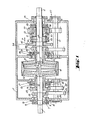
- a drive shaft 1 is arranged in alignment with an output shaft 2.
- a clutch disc 3 is fixedly connected to the free end of the drive shaft 1
- a clutch disc 4 is also fixedly connected to the free end of the output shaft 2.
- a bolt 11 is mounted axially displaceably with respect to both shafts and carries a central coupling body 12.
- the drive shaft 1 is displaceable in its axial direction in the transmission housing 5, the displacement being effected by means of an annular piston 6.
- the piston 6 delimits two annular chambers 7, 8, which can be supplied with pressure medium via only indicated lines 9, 10.
- the two surfaces of the piston 6 delimiting the annular chambers 7, 8 are of different sizes, etc. the piston area delimiting the chamber 7 is larger than that which delimits the chamber 8.
- a second annular chamber 17, 18 delimiting piston 19 can an axial displacement of the hollow shaft 15 can be effected.
- the functions of the chambers 17 and 18 correspond to the chambers 7 and 8, respectively, the chambers 17, 18 being able to be supplied with pressure medium via only indicated lines 20, 21.
- a gear wheel 22 is arranged on the drive shaft 1 in a rotationally fixed manner and a gear wheel 23 is also fixed on the hollow shaft 15 in a rotationally fixed manner.
- the two gear wheels 22, 23 are in constant engagement with the gear wheels 24, 25 of a countershaft 26, whereby the two coaxial shafts 1 and 15 are connected to one another in a first, fixed transmission ratio.
- the output shaft 2 is coaxially surrounded by a hollow shaft 30 which carries a clutch disc 31 at one end.
- the hollow shaft 30 is mounted with respect to the central coupling body 12 as a mirror image of the hollow shaft 15 and axially displaceable. For this purpose, it interacts in the manner already explained with an annular piston 33, which separates two chambers 34, 35 from one another, which can be supplied with pressure medium via only indicated lines 36, 37.
- the cross-sectional area of the piston 33 in the chamber 35, which is acted upon by pressure medium is larger than the piston cross-sectional areas in the chambers 7 and 17, which are acted upon by pressure medium, in order to reliably preclude simultaneous contact of the clutch disks 4 and 31 with the central clutch body 12.
- a gear 38 is arranged in a rotationally fixed manner.
- a second hollow shaft 40 which likewise coaxially surrounds the output shaft 2, carries a ring gear 41.
- An internally toothed ring gear 43 is connected to a gear wheel 42 that is non-rotatably connected to the output shaft, for example by means of a control lever or by means of a pressure medium acted upon piston, in the axial direction of the output shaft 2 in the sense of the double arrow P so that it can be brought into engagement with the ring gear 41 to rigidly connect the hollow shaft 40 to the output shaft 2.
- a gearwheel 50 which coaxially surrounds the hollow shaft 40 in the exemplary embodiment shown, is connected to the gearwheel 38 in a second, predefined transmission ratio via a countershaft 51.
- a freewheel 52 is provided between the hollow shaft 40 and the gear 50, which is designed such that it has a non-positive connection between the gear 50 and when the gear 50 moves relative to the hollow shaft 40 in the sense of a forward rotation of the output shaft 2 of the hollow shaft 40, on the other hand, in the case of relative movement in the opposite direction, ensures free, mutually independent mobility of these two parts.
- the gear 50 is displaceable relative to the hollow shaft 40 by a small amount in the axial direction of the output shaft 2, and the hollow shaft 40 and the gear 50 are provided with interacting friction clutch surfaces 53.
- the axial displacement is effected by means of a pressure medium introduced into an annular chamber via a line 54, which is only indicated. After actuation of this clutch bridging the freewheel 52, the output shaft 2 be braked with the engine. The clutch is released using return springs (not shown).
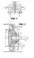
- the gear 50 is fixedly connected to the output shaft 2 according to the schematic illustration in FIG. 2, the transmission parts 40 to 45 and 52 being omitted and the power flow paths in the 1st and 2nd gears due to the elimination of the brackets above Simplify routes.
- the transmission can still be driven with two reverse gears if the ring gears 43 and 44 are brought into engagement with one another. If the gearbox side on the left of the clutch is shifted as in 1st gear, the output is via gear 38, the only indicated gearbox 46 reversing the direction of rotation and gear 45 slowly in a first reverse gear, when shifting the left gear side as in 2nd gear, the downforce is faster with the same parts on the right side of the transmission with a second reverse gear.
- the freely displaceable and rotatably mounted central coupling body 12 can, as indicated in FIG. 2, have a disc shape, but is preferably designed according to FIG. 1 with double-sided conical coupling surfaces, around the peripheral coupling surfaces of the coupling discs 3, 4, 16 and 31 at approximately the same distance Arrange from shafts 1 and 2 and thereby the friction forces occurring during power transmission to keep all coupling surfaces approximately the same size.
- a hydraulic clutch 56 at least in the power flow path assigned to the lowest gears, in the present example, for example, between the clutch disc 31 and the hollow shaft 30 in FIG. 3, in order to soften the load impacts that occur during the switching operations in these gears to be able to record.
- the clutch disc 31 is formed as a component of the pump of a hydraulic clutch 56, which is shown only schematically because the known hydraulic clutch 56, the turbine part of which is connected to the hollow shaft 30.
- a backstop 57 on the shaft of the countershaft 51 which, like a freewheel, rotates the shaft of the countershaft 51 only in one direction allowed. For example, if the sprockets 41 and 43 are in engagement and none of the chambers 7, 17, 35 is pressurized at the same time, then none of the coupling parts 3, 4, 12, 16, 31 is in contact with the other and the transmission is therefore switched to idle . If the vehicle now had the tendency to roll backwards, the shaft 51 would be rotated counter to its normal drive direction, the backstop would engage and prevent the rotation. The vehicle could not roll back. The same would happen if the sprockets 43 and 44 were in engagement; in this case the vehicle could not roll forward. The backstop therefore prevents the vehicle parked on a slope from rolling away, depending on the position of the ring gear 43.
Landscapes
- Engineering & Computer Science (AREA)
- General Engineering & Computer Science (AREA)
- Mechanical Engineering (AREA)
- Structure Of Transmissions (AREA)
- Transmission Devices (AREA)
Applications Claiming Priority (2)
| Application Number | Priority Date | Filing Date | Title |
|---|---|---|---|
| AT0338281A AT386060B (de) | 1981-07-31 | 1981-07-31 | Lastschaltgetriebe |
| AT3382/81 | 1981-07-31 |
Publications (3)
| Publication Number | Publication Date |
|---|---|
| EP0071596A2 true EP0071596A2 (fr) | 1983-02-09 |
| EP0071596A3 EP0071596A3 (en) | 1984-07-25 |
| EP0071596B1 EP0071596B1 (fr) | 1986-11-20 |
Family
ID=3549681
Family Applications (1)
| Application Number | Title | Priority Date | Filing Date |
|---|---|---|---|
| EP82890096A Expired EP0071596B1 (fr) | 1981-07-31 | 1982-06-29 | Transmission à changement de vitesse sous puissance |
Country Status (13)
| Country | Link |
|---|---|
| US (1) | US4466304A (fr) |
| EP (1) | EP0071596B1 (fr) |
| JP (1) | JPS5830551A (fr) |
| AT (1) | AT386060B (fr) |
| BR (1) | BR8204489A (fr) |
| CA (1) | CA1185459A (fr) |
| CS (1) | CS249123B2 (fr) |
| DE (1) | DE3274373D1 (fr) |
| ES (1) | ES514554A0 (fr) |
| PL (1) | PL138546B1 (fr) |
| SU (1) | SU1160943A3 (fr) |
| YU (1) | YU166582A (fr) |
| ZA (1) | ZA825066B (fr) |
Families Citing this family (3)
| Publication number | Priority date | Publication date | Assignee | Title |
|---|---|---|---|---|
| RU2163315C2 (ru) * | 1998-08-24 | 2001-02-20 | Хамин Иван Никифорович | Коробка передач |
| GB2367598A (en) * | 2000-10-04 | 2002-04-10 | Combined Engineering Concepts | A drive transmission for a stern or outboard drive of a watercraft |
| US20070095006A1 (en) * | 2005-11-01 | 2007-05-03 | Konersmann Ronald D | Lightweight portable concrete enclosure and associated method of construction |
Family Cites Families (9)
| Publication number | Priority date | Publication date | Assignee | Title |
|---|---|---|---|---|
| US2261898A (en) * | 1933-06-20 | 1941-11-04 | Jean A H Barkeij | Automatic gearshift transmission for automobiles together with improvements in clutches and gearboxes |
| US2251213A (en) * | 1937-12-06 | 1941-07-29 | Clive W Lanphere | Automatic transmission |
| US2309864A (en) * | 1940-05-16 | 1943-02-02 | Chrysler Corp | Power transmission |
| DE835841C (de) * | 1949-09-09 | 1952-04-07 | Daimler Benz Ag | Schaltvorrichtung fuer Wechselgetriebe, insbesondere fuer Kraftfahrzeuge |
| GB795260A (en) * | 1955-09-29 | 1958-05-21 | Brown David & Sons Ltd | An improvement in or relating to variable-speed gearboxes |
| DE1775249A1 (de) * | 1968-07-19 | 1971-08-12 | Bosch Gmbh Robert | Standraedergetriebe |
| JPS613984B2 (fr) * | 1974-08-19 | 1986-02-06 | Toyota Motor Co Ltd | |
| FR2325857A1 (fr) * | 1975-09-25 | 1977-04-22 | Saviem | Boite de vitesses |
| AT382121B (de) * | 1979-05-09 | 1987-01-12 | Evg Entwicklung Verwert Ges | Lastschaltgetriebe |
-
1981
- 1981-07-31 AT AT0338281A patent/AT386060B/de not_active IP Right Cessation
-
1982
- 1982-06-29 EP EP82890096A patent/EP0071596B1/fr not_active Expired
- 1982-06-29 DE DE8282890096T patent/DE3274373D1/de not_active Expired
- 1982-07-14 US US06/398,286 patent/US4466304A/en not_active Expired - Fee Related
- 1982-07-15 ZA ZA825066A patent/ZA825066B/xx unknown
- 1982-07-23 CS CS825609A patent/CS249123B2/cs unknown
- 1982-07-28 JP JP57130561A patent/JPS5830551A/ja active Pending
- 1982-07-30 BR BR8204489A patent/BR8204489A/pt unknown
- 1982-07-30 CA CA000408528A patent/CA1185459A/fr not_active Expired
- 1982-07-30 YU YU01665/82A patent/YU166582A/xx unknown
- 1982-07-30 PL PL1982237705A patent/PL138546B1/pl unknown
- 1982-07-30 SU SU823467847A patent/SU1160943A3/ru active
- 1982-07-30 ES ES514554A patent/ES514554A0/es active Granted
Also Published As
| Publication number | Publication date |
|---|---|
| ZA825066B (en) | 1983-04-27 |
| JPS5830551A (ja) | 1983-02-23 |
| AT386060B (de) | 1988-06-27 |
| ES8307043A1 (es) | 1983-07-01 |
| BR8204489A (pt) | 1983-07-26 |
| CS249123B2 (en) | 1987-03-12 |
| YU166582A (en) | 1986-08-31 |
| PL237705A1 (en) | 1983-03-28 |
| CA1185459A (fr) | 1985-04-16 |
| US4466304A (en) | 1984-08-21 |
| DE3274373D1 (en) | 1987-01-08 |
| EP0071596B1 (fr) | 1986-11-20 |
| PL138546B1 (en) | 1986-10-31 |
| SU1160943A3 (ru) | 1985-06-07 |
| EP0071596A3 (en) | 1984-07-25 |
| ES514554A0 (es) | 1983-07-01 |
| ATA338281A (de) | 1987-11-15 |
Similar Documents
| Publication | Publication Date | Title |
|---|---|---|
| DE102004022413B4 (de) | Doppelkupplungsgetriebe | |
| EP0248899B1 (fr) | Boite de changement a echelonnement multiple de vitesses | |
| DE3822110B4 (de) | Zahnräderwechselgetriebe für einen Traktor | |
| EP2487385A2 (fr) | Boîte de vitesse pour véhicules automobiles | |
| DE4338368A1 (de) | Zahnradgetriebe mit Kettenantrieb für Richtungsumkehr | |
| DE2921547C2 (de) | Kraftuebertragungsmechanismus fuer fahrzeuge | |
| DE3634327A1 (de) | Getriebe mit mehreren vorwaerts- und rueckwaertsgaengen | |
| EP0552673B1 (fr) | Boîte de vitesse pour véhicule à moteur | |
| DE19544352B4 (de) | Fahrzeuggetriebe | |
| WO2005028236A1 (fr) | Ensemble transmission | |
| DE3841390A1 (de) | Zahnraederwechselgetriebe fuer kraftfahrzeuge | |
| CH440999A (de) | Wechselgetriebe | |
| EP0105124A1 (fr) | Boîte de vitesses à construction en groupes | |
| EP0019609B1 (fr) | Transmission manoeuvrable sous charge | |
| DE4446482C1 (de) | Zahnstangenlenkung | |
| DE4115989A1 (de) | Gangschaltgetriebe fuer ein kraftfahrzeug mit doppelkupplung | |
| EP0071596B1 (fr) | Transmission à changement de vitesse sous puissance | |
| DE3048770A1 (de) | Zahnradwechselgetriebe | |
| DE19512642A1 (de) | Schaltgetriebe | |
| DE4222115A1 (de) | Getriebeanordnung fuer fahrzeuge | |
| EP0079879B1 (fr) | Transmission manoeuvrable sous charge | |
| DE3527401A1 (de) | Stufenschaltgetriebe, insbesondere fuer kraftfahrzeuge | |
| DE908702C (de) | Kraftschluessiges Mehrganggetriebe, insbesondere fuer Kraftfahrzeuge | |
| DE4127609A1 (de) | Zahnraederwechselgetriebe in vorgelegebauweise fuer ein kraftfahrzeug | |
| DE3324434C2 (de) | Planetenradgetriebe |
Legal Events
| Date | Code | Title | Description |
|---|---|---|---|
| PUAI | Public reference made under article 153(3) epc to a published international application that has entered the european phase |
Free format text: ORIGINAL CODE: 0009012 |
|
| AK | Designated contracting states |
Designated state(s): BE CH DE FR GB IT LI LU NL SE |
|
| 17P | Request for examination filed |
Effective date: 19830331 |
|
| PUAL | Search report despatched |
Free format text: ORIGINAL CODE: 0009013 |
|
| AK | Designated contracting states |
Designated state(s): BE CH DE FR GB IT LI LU NL SE |
|
| ITF | It: translation for a ep patent filed | ||
| GRAA | (expected) grant |
Free format text: ORIGINAL CODE: 0009210 |
|
| AK | Designated contracting states |
Kind code of ref document: B1 Designated state(s): BE CH DE FR GB IT LI LU NL SE |
|
| REF | Corresponds to: |
Ref document number: 3274373 Country of ref document: DE Date of ref document: 19870108 |
|
| ET | Fr: translation filed | ||
| PG25 | Lapsed in a contracting state [announced via postgrant information from national office to epo] |
Ref country code: LU Free format text: LAPSE BECAUSE OF NON-PAYMENT OF DUE FEES Effective date: 19870630 |
|
| PGFP | Annual fee paid to national office [announced via postgrant information from national office to epo] |
Ref country code: NL Payment date: 19870630 Year of fee payment: 6 |
|
| PLBE | No opposition filed within time limit |
Free format text: ORIGINAL CODE: 0009261 |
|
| STAA | Information on the status of an ep patent application or granted ep patent |
Free format text: STATUS: NO OPPOSITION FILED WITHIN TIME LIMIT |
|
| 26N | No opposition filed | ||
| PG25 | Lapsed in a contracting state [announced via postgrant information from national office to epo] |
Ref country code: GB Effective date: 19880629 |
|
| PG25 | Lapsed in a contracting state [announced via postgrant information from national office to epo] |
Ref country code: SE Effective date: 19880630 Ref country code: LI Effective date: 19880630 Ref country code: CH Effective date: 19880630 |
|
| BERE | Be: lapsed |
Owner name: EVG ENTWICKLUNGS- U. VERWERTUNGS- G.M.B.H. Effective date: 19880630 |
|
| PG25 | Lapsed in a contracting state [announced via postgrant information from national office to epo] |
Ref country code: NL Effective date: 19890101 |
|
| NLV4 | Nl: lapsed or anulled due to non-payment of the annual fee | ||
| GBPC | Gb: european patent ceased through non-payment of renewal fee | ||
| PG25 | Lapsed in a contracting state [announced via postgrant information from national office to epo] |
Ref country code: FR Free format text: LAPSE BECAUSE OF NON-PAYMENT OF DUE FEES Effective date: 19890228 |
|
| REG | Reference to a national code |
Ref country code: CH Ref legal event code: PL |
|
| PG25 | Lapsed in a contracting state [announced via postgrant information from national office to epo] |
Ref country code: DE Effective date: 19890301 |
|
| REG | Reference to a national code |
Ref country code: FR Ref legal event code: ST |
|
| PG25 | Lapsed in a contracting state [announced via postgrant information from national office to epo] |
Ref country code: BE Effective date: 19890630 |
|
| EUG | Se: european patent has lapsed |
Ref document number: 82890096.9 Effective date: 19890220 |