EP0071795A2 - Arme à feu individuelle automatique - Google Patents
Arme à feu individuelle automatique Download PDFInfo
- Publication number
- EP0071795A2 EP0071795A2 EP82106350A EP82106350A EP0071795A2 EP 0071795 A2 EP0071795 A2 EP 0071795A2 EP 82106350 A EP82106350 A EP 82106350A EP 82106350 A EP82106350 A EP 82106350A EP 0071795 A2 EP0071795 A2 EP 0071795A2
- Authority
- EP
- European Patent Office
- Prior art keywords
- piston
- delay
- fire
- firearm according
- cock
- Prior art date
- Legal status (The legal status is an assumption and is not a legal conclusion. Google has not performed a legal analysis and makes no representation as to the accuracy of the status listed.)
- Granted
Links
Images


Classifications
-
- F—MECHANICAL ENGINEERING; LIGHTING; HEATING; WEAPONS; BLASTING
- F41—WEAPONS
- F41A—FUNCTIONAL FEATURES OR DETAILS COMMON TO BOTH SMALLARMS AND ORDNANCE, e.g. CANNONS; MOUNTINGS FOR SMALLARMS OR ORDNANCE
- F41A19/00—Firing or trigger mechanisms; Cocking mechanisms
- F41A19/03—Shot-velocity control
Definitions
- the invention relates to a handgun that can be switched to single fire, burst of fire and continuous fire.
- the weapon fires a predetermined number of shots, preferably three shots, in rapid succession when the trigger is pulled once.
- the shot cadence should be as high as possible. A high rate of fire is of particular importance in the case of reloaded handguns, because the gunner does not feel any recoil during the firing of the burst of fire and the weapon is therefore not or only slightly deflected from the target.
- the object of the present invention is, therefore, darip to design an automatic handgun of the type mentioned at the outset in such a way that it has the highest possible firing rate in the firing shot setting and a significantly reduced firing rate in the continuous fire setting.
- a handgun of the type mentioned at the outset in that it has a firing cadence regulator which reduces the firing cadence in the continuous fire setting by means of a delay element which releases the triggering of the next shot, and that by means of the delay element a cock acting on a firing pin when the weapon is fired can be triggered that the tap is provided with an additional detent, which is effective in the continuous fire position and can be triggered by the delay element, and that the additional detent of the tap comprises a delay release lever which is provided with a nose engaging in a stopper which is provided by the Delay element can be disengaged.
- the advantage of such a handgun is that in the firing position it is possible to shoot with a very high firing rate, which leads to a high hit rate, especially when the invention is implemented with a gun mount, such as this from DE-OS 23 26 525 and the corresponding U.S. Patent 4,024,792.
- a gun mount such as this from DE-OS 23 26 525 and the corresponding U.S. Patent 4,024,792.
- three or more shots can be fired in the firing position before the recoil affects the shooter and thus the alignment of the gun.
- the shots fired during a burst of fire can be kept within a very narrow scatter circle.
- the shot cadence is reduced, for example, to 300 or less shots per minute, that is to five or fewer shots per second.
- Another advantage is that the delay time of the delay element can be set independently of the kinematics and the movement sequences of the weapon, because the delay element practically does not intervene in the movement sequence of the weapon system, but only releases the tap with a delay, which has no repercussions on the Movements of closure, cartridge feed and the like.
- the additional detent makes it possible to leave the trigger system of known weapons essentially unchanged and only to supplement it with the additional detent and the delay element.
- the delay release lever can be attached in a desired manner away from the other cock catches, which in turn are preferably incorporated in the vicinity of the axis of rotation of the cock.
- the delay lever can be made long enough so that the delay element requires a relatively small force to disengage the delay release lever and to release the tap.
- an engagement surface for the deceleration release lever is provided in the region of the end region of the valve that is remote from the axis of rotation of the valve.
- the cadence reduction by means of the delay element can be switched off by holding the delay release lever in a position in which it always remains out of engagement with the engagement surface on the tap.
- a particularly expedient embodiment is obtained when the safety shaft, which is in any case available for switching on the usual operating modes, is designed such that it holds the delay release lever in a pivoted position in the burst of fire position, in which its nose remains outside the engagement surface of the stop cock.
- This embodiment has the advantage that the safety shaft automatically deactivates the delay element in the firing position, but on the other hand allows the delay element to take effect in the continuous fire position.
- the delay lever is disengaged from its active position via a link in the automatic counting device which limits the number of shots of the burst of fire.
- the delay lever is only pivoted out during the shot count and is therefore ineffective, but is also effective in the setting for individual fires, but this has no influence in practical use.
- the delay element can be designed as desired within wide limits and can be designed functionally differently.
- a mechanical-hydraulic unit it can be similar to a one-way shock absorber be formed which has a piston guided in a cylinder, the cylinder being filled with hydraulic fluid and the piston being provided with throttles and check valves connected in parallel and being loaded by a spring.
- This delay element is activated by inserting the piston in the direction in which the check valves open. It is then pushed back in the opposite direction by the spring, the hydraulic fluid having to flow through throttle bores in the piston, which results in the desired deceleration.
- Hydraulic delay elements generally have the disadvantage that their delay time is temperature-dependent, because the viscosity of the liquid depends on the prevailing temperature.
- a dependence of the delay time on the outside temperature is not permissible for a weapon that has to function in the tropical climate as well as in the Arctic.
- a mechanical-pneumatic delay element is therefore preferably provided, which comprises a spring-loaded piston and which projects into the movement path of the breech, which shifts the piston before the next shot is fired and tensions the piston spring which retards the piston with a throttle retarded.
- a pneumatic delay element works reliably and practically completely independent of temperature. In principle, it can be constructed like the previously described shock absorber, that is, it can be hermetically sealed from the outside, which has the advantage of being insensitive to dirt and dust.
- the piston is provided with a cup sleeve serving as a check valve and it is the cylinder guiding the piston on one or both sides vented via an optionally adjustable throttle.
- a cup sleeve serving as a check valve and it is the cylinder guiding the piston on one or both sides vented via an optionally adjustable throttle.
- This embodiment is characterized by a particularly simple construction because the piston is essentially formed by the cup sleeve, which at the same time also fulfills the function of the check valve.
- an externally adjustable throttle can easily be used, which has the advantage that the delay time can be set, which will only be important in exceptional cases, however, because in large-scale production the provision of a fixed throttle is more appropriate.
- the throttle can be provided on the pressure side and / or the suction side.
- the cylinder is provided with a transverse bore, which the piston releases before it reaches its active end position.
- This cross bore results in the effect that the deceleration caused by the throttle is switched off at the moment and the piston is moved without delay by the spring when the piston has passed the cross bore. It is thereby achieved that the delay release lever is actuated with the full and undelayed force of the spring displacing the piston. This results in a uniform and very reliable working of the device. It can also have a similar effect aims that the piston rod is sealed in the support plate and is provided with a longitudinal groove which reaches and bridges the seal before reaching the Virk end position of the piston, or that a groove is provided in the cylinder wall.
- such automatic handguns are provided with a return buffer for limiting the return of the breech.
- the return buffer is designed as a ring surrounding the piston rod of the delay-element piston, against which a collar attached to the piston rod comes to rest in the closed end position. This makes it possible to mount the delay element in the end region of the breech movement path, as a result of which the delay element is integrated into the weapon and an organic, compact construction is achieved.
- the weapon shown in FIG. 1 which is an automatic rifle, comprises a barrel 1, a sighting device 2, a hand guard 3 surrounding the rear part of the barrel, a pistol grip 4 with a trigger 6 pivotally mounted in a trigger box 5 and a shoulder rest 7.
- a cartridge supply is located in a magazine 8 attached in front of the trigger box 5.
- the weapon is designed as a recoil loader like the known G 3 rifle; it could also be constructed as a gas pressure charger.
- the handgun includes a breech that closes the barrel, returns after a shot has been fired, ejects the empty cartridge, advances under the force of a spring, and thereby inserts the next cartridge into the chamber.
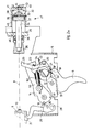
- FIGS. 2a-c show the rear part of the breech, the breech being in its front end position in which it closes the cartridge chamber.
- a breech block 9 with a firing pin 10 is displaceable along a line 11 when the breech moves back and then forwards again.
- the trigger 6 is rotatably mounted in the trigger box 5 about an axis 12.
- a trigger lever 13 is also pivotable about the axis 12 and can be displaced longitudinally to a limited extent, as is known from the aforementioned weapon.
- a tap 14 is pivotable about an axis 15 and is provided with a catch 16 and a further catch 17 at a short distance from its axis 15.
- the cock 14 is loaded in a known manner by a cock spring which, after being released in the illustration according to FIG. 2a, pivots it counterclockwise until it hits the firing pin 10 hits and thus triggers the shot.
- a safety shaft 18 is provided parallel to the axes 12 and 15 and, in a known, not shown manner, in the "" secured “position blocks an extension 19 of the trigger 6 and thus an actuation of the trigger 6.
- Around a further axis 20 is a delay release lever 21 is pivotally mounted, which is loaded clockwise by a spring 22.
- the delay release lever 21 is provided with a nose 23 which engages in a catch 24 which is incorporated in the cock 14 in its end region facing away from the axis 15.
- the delay release lever 21 is furthermore extends and protrudes with an arm 25 into the path of movement of a head 26 of a delay element 27 or 27 'or 27 ", the head 26 also being movable along the line 11, although the arm 25 is laterally outside the path of movement of the Closure carrier 9 is located.
- a catch pawl 29 is rotatably mounted about an axis 28 and is provided with a nose 30, on which the cock 14 with the catch 16 comes to rest when the catch pawl 29 is not pivoted out.
- the end of the catch pawl protrudes into the movement path of a release lever 31 attached to the closure support 9 and movable with it.
- the catch pawl 29 is pivoted such that the nose 30 is outside the movement path of the catch 16 and thus the tap 14, as far as it is not held otherwise, can hit the firing pin 10.
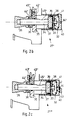
- the delay members 27, 27 'and 27' ' comprise a cylinder 32 fastened to the trigger box 5 or the lock guide, in which a piston 33 is displaceably guided in the direction of line 11, which is provided with a piston rod 34, on the piston 33 of which opposite end of the head 26 is attached.
- the piston rod 34 is passed through a support plate 35 fixedly attached to the weapon and a ring 36, which surrounds the piston rod 34 and is made of an elastically deformable material and serves as a buffer, is provided between the head 26 and the support plate 35.
- the piston 33 comprises a support plate 37 and a guide plate 38 which fix a cup sleeve 39 made of an elastic sealing material between them. The open side of the pot sleeve 39 points towards the head 26.
- a helical compression spring 41 is supported on a bottom 40 of the cylinder 32, which on the other hand rests on the guide plate 38 and loads the piston 33, so that it moves towards the closure carrier 9 tries to move.
- a bore 42 is machined into the bottom 40 of the cylinder 32, which bore can be completely or partially covered by a plate 44 pivotably fastened by means of a screw 43 a transverse bore 45 is incorporated, the position of which is selected such that the cup sleeve 39 has passed the bore under the action of the compression spring 41, just before the head 26 reaches the arm 25.
- the bore 45 is replaced by a longitudinal groove 45 'in the piston rod 34, which is sealed by an O-ring 47 in the support plate 35 until the groove 45' extends outward through the sealed area. Both the negative pressure and the excess pressure are used in the delay element 27 ′′ according to FIG. 2c.
- the various operating modes namely safe, single fire, burst of fire and continuous fire are set in a known manner by pivoting the safety shaft 18.
- the safety shaft blocks the shoulder 19 of the trigger 6, as is also known from the imported weapons G 3 and HK 21 A 1.
- the catch pawl 29 is pivoted by the release lever 31 and thus the nose 30 is disengaged from the catch 16.
- the trigger 6 can be pivoted and takes the trigger lever 13 with it, the stud of which pivots out of the catch 17 and releases the tap 14.
- the breech runs back, tensions the cock 14 and then runs again under the action of a closing spring, not shown.
- the tap 14 is first caught by the nose 30 at the catch 16 until the closure carrier 9 reaching the closed position with the release lever 31 swings out the catch pawl 29, whereupon the tap 14 is caught by the trigger lever 13 with its catch 17.
- the trigger 6 By pulling the trigger 6 again, the next scrm. to be triggered.
- a cam 18 'of the safety shaft 18 pivots the delay lever 21 so that its nose 23 is out of engagement with the catch 24 of the cock 14. This ensures that the next shot is triggered each time the breech carrier 9 reaches the closed position of the breech and the release lever 31 swings out the catch pawl 29, as a result of which the nose 30 is released from the catch 16 and the cock 14 can therefore be knocked off.
- the delay release lever 21 is also inoperative in this operating mode.
- the cup sleeve 39 acting as a non-return valve opening in this direction of movement.
- the spring 41 presses the piston 33 in the direction of the closure carrier 9, the piston speed depending on how large the free cross section of the bore 42 or 42 'is which by Ver turn the screw 43 and the plate 44 is adjustable (unless a fixed hole is preferred).
- the piston 33 therefore moves with a delay until the cup sleeve 39 has passed the transverse bore 45 (FIG.
- the groove 45 ' has passed the O-ring 47, whereupon the cross bore 45 and the groove 45' have air practically unthrottled in the or can flow out of the cylinder 32, whereupon the piston 33 with the piston rod 34 and the head 26 is moved forward without delay by the spring 41 until the head 26 hits the arm 25 and pivots the delay release lever 21.
- the nose 23 is released from the rest 24 and the tap 14 can knock off and trigger the shot.
- the time interval between two shots is no longer determined solely by the kinematics of the shutter, but essentially by the delay time determined by the delay element 27. So while in the burst position the weapon shoots with unchanged, high cadence, in the continuous fire position it shoots with a reduced cadence.
- the cadence can be set to 300 rounds per minute or, if desired, even a lot lower, but the firearm's full high cadence is retained in the mode of operation.
- the delay element 27 can also be constructed in a different manner known per se in mechanical delay elements.
- a mechanical delay element for example, an electrical delay element could also be used which, after its delay time has expired, for example via a magnet, releases the tap 14.
- the cock 14 is loaded in a known manner via a pressure fork 50 by a helical compression spring 52. These parts are shown broken off to simplify the drawing. Also to simplify the drawing, only a gear 54 of the shot counter present in the weapon is shown in FIG. 2a, which is driven in a manner not shown by the movement of the cock 14.
- This shot counter is in European patent application no. 82 102 962.6 * dated April 7, 1982, the applicant of which is Heckler & Koch GmbH and whose title is "Shot number limiter for automatic firearms with cock-fired ignition" and which is the priority of German patent application P 31 20 128.8 claimed, described in detail. This reference to the European patent application mentioned makes the entire content of the European patent application the content of the present patent application.
- the pneumatic delay element 60 shown in FIG. 3 differs from the delay elements described above mainly in that it has in its piston 62 a valve 66 which is loaded by a spring 64 and which moves from the left to the left when the piston 62 moves in FIG. 3 * designated countries: Austria, Belgium, Switzerland with Liechtenstein, France, United Kingdom, Italy, Netherlands, Sweden opens automatically on the right, thereby allowing the air originally contained on the right of the piston 62 within the cylinder 68 to pass through a radial bore 70 into the area on the left of the piston 62. If the piston 62 moves to the left from the position shown in FIG.
- valve 66 closes and the air located to the left of the piston 62 now passes through the radial bore 70 and a bore 74 running parallel to the axial direction, which is at its end Bore 70 adjacent end merges into a narrow throttle bore 76, again on the right side of the piston 62.
- a longitudinal groove 82 is provided which, when the piston 62 has moved a certain distance to the left, the rapid overflow of the Air from the space to the left of the piston 62 into the space to the right of the piston 62 allows the air to flow past a seal 86 located in an annular groove 84, thereby bypassing the throttle bore 76 and thereby the spring 41 the piston 62, as in the above described embodiments, drives to the left at considerable speed, so that the triggering of the hammer 14 takes place with great certainty.
- the arrangement shown in FIG. 3 is insensitive to contamination because all parts of the pneumatic delay device are arranged inside the cylinder 68 and are closed off by this and the wall 35 to the outside.
Landscapes
- Engineering & Computer Science (AREA)
- General Engineering & Computer Science (AREA)
- Portable Nailing Machines And Staplers (AREA)
- Pharmaceuticals Containing Other Organic And Inorganic Compounds (AREA)
- Medicinal Preparation (AREA)
- Acyclic And Carbocyclic Compounds In Medicinal Compositions (AREA)
- Automotive Seat Belt Assembly (AREA)
- Vending Machines For Individual Products (AREA)
- Control Of Driving Devices And Active Controlling Of Vehicle (AREA)
- Percussive Tools And Related Accessories (AREA)
- Toys (AREA)
- Non-Silver Salt Photosensitive Materials And Non-Silver Salt Photography (AREA)
- Agricultural Chemicals And Associated Chemicals (AREA)
- Nitrogen And Oxygen Or Sulfur-Condensed Heterocyclic Ring Systems (AREA)
Priority Applications (1)
| Application Number | Priority Date | Filing Date | Title |
|---|---|---|---|
| AT82106350T ATE23631T1 (de) | 1981-08-04 | 1982-07-15 | Automatische handfeuerwaffe. |
Applications Claiming Priority (2)
| Application Number | Priority Date | Filing Date | Title |
|---|---|---|---|
| DE3130761A DE3130761C2 (de) | 1981-08-04 | 1981-08-04 | Automatische Handfeuerwaffe oder Maschinengewehr |
| DE3130761 | 1981-08-04 |
Publications (3)
| Publication Number | Publication Date |
|---|---|
| EP0071795A2 true EP0071795A2 (fr) | 1983-02-16 |
| EP0071795A3 EP0071795A3 (en) | 1983-08-10 |
| EP0071795B1 EP0071795B1 (fr) | 1986-11-12 |
Family
ID=6138516
Family Applications (1)
| Application Number | Title | Priority Date | Filing Date |
|---|---|---|---|
| EP82106350A Expired EP0071795B1 (fr) | 1981-08-04 | 1982-07-15 | Arme à feu individuelle automatique |
Country Status (8)
| Country | Link |
|---|---|
| US (1) | US4523509A (fr) |
| EP (1) | EP0071795B1 (fr) |
| AT (1) | ATE23631T1 (fr) |
| CA (1) | CA1209835A (fr) |
| DE (1) | DE3130761C2 (fr) |
| IL (1) | IL66440A (fr) |
| NO (1) | NO155024C (fr) |
| PT (1) | PT75368B (fr) |
Cited By (1)
| Publication number | Priority date | Publication date | Assignee | Title |
|---|---|---|---|---|
| US8042296B1 (en) | 2007-12-27 | 2011-10-25 | Gerhard Kirstein | Semiautomatic or fully automatic firearm |
Families Citing this family (30)
| Publication number | Priority date | Publication date | Assignee | Title |
|---|---|---|---|---|
| GB2267558B (en) * | 1992-05-12 | 1996-07-10 | Bushman Ltd | Fire rate control system |
| FR2721388B1 (fr) * | 1994-06-16 | 1996-08-14 | Giat Ind Sa | Procédé et système pour freiner le mouvement d'une pièce armée par un ressort et animée d'un mouvement pivotant alternatif. |
| US5640794A (en) * | 1995-07-07 | 1997-06-24 | Fn Manufacturing, Inc. | Fire control mechanism for an automatic pistol |
| US5722383A (en) * | 1995-12-01 | 1998-03-03 | Tippmann Pneumatics, Inc. | Impeder for a gun firing mechanism with ammunition feeder and mode selector |
| US5770814A (en) * | 1996-05-09 | 1998-06-23 | Defense Technologies Limited | Firing rate regulating mechanism |
| US6125735A (en) * | 1996-10-21 | 2000-10-03 | Heckler & Koch Gmbh | Self-loading weapon |
| US6019024A (en) * | 1998-01-26 | 2000-02-01 | Zdf Import Export, Inc. | Compact operating system for automatic rifles |
| DE19846657C2 (de) | 1998-10-09 | 2001-02-15 | Heckler & Koch Gmbh | Abschlageinrichtung mit vermindertem Abzugsgewicht |
| US6305367B1 (en) | 1999-02-26 | 2001-10-23 | Airgun Designs, Inc. | Hopper feeder |
| US6488019B2 (en) | 1999-02-26 | 2002-12-03 | Thomas G. Kotsiopoulos | Feeder for a paintball gun |
| US6467473B1 (en) | 1999-02-26 | 2002-10-22 | Airgun Designs, Inc. | Paintball feeders |
| RU2219457C2 (ru) * | 1999-04-12 | 2003-12-20 | Мармышев Валентин Николаевич | Механизм взведения |
| SG103860A1 (en) * | 2002-05-16 | 2004-05-26 | Ordnance Dev And Engineering C | Firing rate regulating mechanism |
| US7596900B2 (en) * | 2003-08-04 | 2009-10-06 | Rmdi, L.L.C. | Multi-caliber ambidextrously controllable firearm |
| US7971379B2 (en) | 2004-02-13 | 2011-07-05 | Rmdi, Llc | Firearm |
| DE102005026978A1 (de) * | 2005-06-10 | 2006-12-14 | Diehl Bgt Defence Gmbh & Co. Kg | Automatisch schießende Waffe |
| US20080251655A1 (en) * | 2007-04-12 | 2008-10-16 | Housley Todd B | Bottle Holder |
| USD694352S1 (en) * | 2009-09-02 | 2013-11-26 | German Sport Guns Gmbh | Semi-automatic firearm |
| USD670350S1 (en) * | 2009-10-26 | 2012-11-06 | German Sport Guns Gmbh | Semi-automatic firearm magazine |
| USD637678S1 (en) * | 2010-05-06 | 2011-05-10 | Rock River Arms, Inc. | Firearm |
| USD636048S1 (en) * | 2010-05-06 | 2011-04-12 | Rock River Arms, Inc. | Firearm |
| USD636454S1 (en) * | 2010-05-06 | 2011-04-19 | Rock River Arms, Inc. | Firearm |
| USD667072S1 (en) * | 2010-06-06 | 2012-09-11 | ISSC Handels GmbH | Semi-automatic fire arm |
| USD689160S1 (en) * | 2012-06-02 | 2013-09-03 | Dietmar Emde | Semi-automatic firearm |
| TWI535993B (zh) * | 2014-03-06 | 2016-06-01 | Zhao-Xiong Zhuo | Air gun firing control device |
| US10401102B1 (en) | 2015-07-31 | 2019-09-03 | Aaron J. Carroll | Firearm conversion device |
| DE102016004678B4 (de) | 2016-04-19 | 2019-05-09 | KTS Patentmanagement und Vorentwicklung GmbH | Halbautomatische oder vollautomatische Feuerwaffe |
| USD903032S1 (en) * | 2017-10-24 | 2020-11-24 | German Sport Guns Gmbh | Firearm |
| DE102018005127B4 (de) | 2018-06-28 | 2022-11-10 | KTS Patentmanagement und Vorentwicklung GmbH | Halbautomatische oder vollautomatische Feuerwaffe |
| WO2020117344A2 (fr) * | 2018-09-06 | 2020-06-11 | Reynolds George L | Mécanisme de commande de vitesse pour armes à feu entièrement automatiques |
Family Cites Families (15)
| Publication number | Priority date | Publication date | Assignee | Title |
|---|---|---|---|---|
| US1464276A (en) * | 1922-03-31 | 1923-08-07 | Vincon Gustavo | Automatic firearm |
| US1604447A (en) * | 1925-07-23 | 1926-10-26 | Heuser Mfg Company | Cushion-spring screen-door check |
| DE565370C (de) * | 1932-10-21 | 1932-11-29 | Simson & Co | Einsatzeinrichtung zum Verfeuern von Kleinkalibermunition aus Maschinengewehren |
| DE687499C (de) * | 1936-10-07 | 1940-01-31 | Gustav Genschow & Co Akt Ges | Selbsttaetige Feuerwaffe mit pneumatischer Bremse zum Verlangsamen der Feuergeschwindigkeit |
| US2791942A (en) * | 1954-01-08 | 1957-05-14 | David C Fletcher | Rate reducer for a firearm |
| US2873650A (en) * | 1957-05-24 | 1959-02-17 | Jr Harry E Pinkerton | Fluid transfer rate control for a firing mechanism |
| DE1121981B (de) * | 1958-05-24 | 1962-01-11 | Fritz Walther | Vorrichtung zum wahlweisen Einstellen von Dauerfeuer, Serienfeuer oder Einzelschuss an automatischen Handfeuerwaffen |
| US3301133A (en) * | 1965-01-21 | 1967-01-31 | Colt S Inc | Mechanism for changing rate of automatic fire |
| DE2018620C3 (de) * | 1970-04-17 | 1975-10-23 | Rheinmetall Gmbh, 4000 Duesseldorf | Kadenz- und Rhythmussteuergerät für Maschinenwaffen |
| US3650177A (en) * | 1970-07-01 | 1972-03-21 | Mauser Werke Ag | Device for controlling the firing frequency in automatic firearms |
| GB1420626A (en) * | 1972-10-02 | 1976-01-07 | Sturm Ruger & Co | Auto-loading firearm |
| AT331675B (de) * | 1973-05-24 | 1976-08-25 | Heckler & Koch Gmbh | Automatische handfeuerwaffe |
| JPS583160B2 (ja) * | 1976-03-19 | 1983-01-20 | トキコ株式会社 | 圧力容器へのガス封入方法 |
| CH594864A5 (fr) * | 1976-10-27 | 1978-01-31 | Oerlikon Buehrle Ag | |
| DE3120128C1 (de) * | 1981-05-20 | 1982-12-09 | Heckler & Koch Gmbh, 7238 Oberndorf | Schusszahlbegrenzer fuer automatische Feuerwaffen mit Hahnschlagzuendung |
-
1981
- 1981-08-04 DE DE3130761A patent/DE3130761C2/de not_active Expired
-
1982
- 1982-07-15 EP EP82106350A patent/EP0071795B1/fr not_active Expired
- 1982-07-15 AT AT82106350T patent/ATE23631T1/de not_active IP Right Cessation
- 1982-07-27 US US06/402,268 patent/US4523509A/en not_active Expired - Lifetime
- 1982-07-28 CA CA000408278A patent/CA1209835A/fr not_active Expired
- 1982-08-02 IL IL66440A patent/IL66440A/xx not_active IP Right Cessation
- 1982-08-03 NO NO822653A patent/NO155024C/no unknown
- 1982-08-03 PT PT75368A patent/PT75368B/pt unknown
Cited By (1)
| Publication number | Priority date | Publication date | Assignee | Title |
|---|---|---|---|---|
| US8042296B1 (en) | 2007-12-27 | 2011-10-25 | Gerhard Kirstein | Semiautomatic or fully automatic firearm |
Also Published As
| Publication number | Publication date |
|---|---|
| ATE23631T1 (de) | 1986-11-15 |
| IL66440A (en) | 1987-10-20 |
| NO822653L (no) | 1983-02-07 |
| NO155024B (no) | 1986-10-20 |
| PT75368B (de) | 1984-08-20 |
| EP0071795A3 (en) | 1983-08-10 |
| PT75368A (de) | 1982-09-01 |
| DE3130761C2 (de) | 1984-01-05 |
| US4523509A (en) | 1985-06-18 |
| CA1209835A (fr) | 1986-08-19 |
| NO155024C (no) | 1987-01-28 |
| EP0071795B1 (fr) | 1986-11-12 |
| DE3130761A1 (de) | 1983-03-03 |
Similar Documents
| Publication | Publication Date | Title |
|---|---|---|
| EP0071795B1 (fr) | Arme à feu individuelle automatique | |
| DE4109777C2 (fr) | ||
| DE3244315C2 (de) | Automatische Handfeuerwaffe mit starr verriegeltem Verschluß für Munition mit extrem hohem Geschoßimpuls | |
| WO2000022367A1 (fr) | Dispositif de detente | |
| DE640721C (de) | Selbstladepistole mit Spannabzug und Hahn | |
| DE2627641C2 (de) | Griffspanner-Selbstladepistole | |
| DE844558C (de) | Automatische Feuerwaffe mit einteiligem Verschluss | |
| EP4180758B1 (fr) | Serrure d'une arme de chasse ou de sport pourvue de dispositifs de sécurité | |
| AT393028B (de) | Gasentnahmesystem fuer eine feuerwaffe | |
| DE3035796A1 (de) | Selbstladepistole | |
| DE1096806B (de) | Selbsttaetige Feuerwaffe | |
| DE3740219C2 (de) | Abzugseinrichtung für Schußwaffen | |
| DE910625C (de) | Trommelrevolver | |
| DE869017C (de) | Selbstlade-Sportgewehr | |
| CH184905A (de) | Scheibenpistole. | |
| EP0785405B1 (fr) | Arme à gas comprimé | |
| DE60320333T2 (de) | Automatische oder Halbautomatische Feuerwaffe | |
| DE657148C (de) | Vorderladersignalpistole mit einer Patronenfesthalteklinke, die von der Pistolenaussenseite betaetigbar ist | |
| DE1166052B (de) | Einsatzgeraet mit Einstecklauf zum Verschiessen von Kleinkaliber-Munition durch automatische Handfeuerwaffen, insbesondere Sturmgewehre mit Hammerzuendung | |
| DE2162260C3 (fr) | ||
| DE452605C (de) | Selbsttaetige Handfeuerwaffe | |
| EP0081097A2 (fr) | Pistolet à gaz comprimé muni d'une cartouche à gaz carbonique | |
| EP0054239A1 (fr) | Arme à feu semi-automatique | |
| DE2024751A1 (en) | Beating up weft picks | |
| DE2326525C3 (de) | Als Gasdrucklader ausgebildete Handfeuerwaffe |
Legal Events
| Date | Code | Title | Description |
|---|---|---|---|
| PUAI | Public reference made under article 153(3) epc to a published international application that has entered the european phase |
Free format text: ORIGINAL CODE: 0009012 |
|
| AK | Designated contracting states |
Designated state(s): AT BE CH FR GB IT LI NL SE |
|
| PUAL | Search report despatched |
Free format text: ORIGINAL CODE: 0009013 |
|
| AK | Designated contracting states |
Designated state(s): AT BE CH FR GB IT LI NL SE |
|
| 17P | Request for examination filed |
Effective date: 19840112 |
|
| GRAA | (expected) grant |
Free format text: ORIGINAL CODE: 0009210 |
|
| AK | Designated contracting states |
Kind code of ref document: B1 Designated state(s): AT BE CH FR GB IT LI NL SE |
|
| REF | Corresponds to: |
Ref document number: 23631 Country of ref document: AT Date of ref document: 19861115 Kind code of ref document: T |
|
| ET | Fr: translation filed | ||
| ITF | It: translation for a ep patent filed | ||
| PLBE | No opposition filed within time limit |
Free format text: ORIGINAL CODE: 0009261 |
|
| STAA | Information on the status of an ep patent application or granted ep patent |
Free format text: STATUS: NO OPPOSITION FILED WITHIN TIME LIMIT |
|
| 26N | No opposition filed | ||
| PGFP | Annual fee paid to national office [announced via postgrant information from national office to epo] |
Ref country code: SE Payment date: 19890621 Year of fee payment: 8 |
|
| PGFP | Annual fee paid to national office [announced via postgrant information from national office to epo] |
Ref country code: BE Payment date: 19890628 Year of fee payment: 8 |
|
| PGFP | Annual fee paid to national office [announced via postgrant information from national office to epo] |
Ref country code: GB Payment date: 19890630 Year of fee payment: 8 |
|
| PGFP | Annual fee paid to national office [announced via postgrant information from national office to epo] |
Ref country code: FR Payment date: 19890720 Year of fee payment: 8 |
|
| ITTA | It: last paid annual fee | ||
| PGFP | Annual fee paid to national office [announced via postgrant information from national office to epo] |
Ref country code: NL Payment date: 19890731 Year of fee payment: 8 Ref country code: AT Payment date: 19890731 Year of fee payment: 8 |
|
| PGFP | Annual fee paid to national office [announced via postgrant information from national office to epo] |
Ref country code: CH Payment date: 19890927 Year of fee payment: 8 |
|
| PG25 | Lapsed in a contracting state [announced via postgrant information from national office to epo] |
Ref country code: GB Effective date: 19900715 Ref country code: AT Effective date: 19900715 |
|
| PG25 | Lapsed in a contracting state [announced via postgrant information from national office to epo] |
Ref country code: SE Effective date: 19900716 |
|
| PG25 | Lapsed in a contracting state [announced via postgrant information from national office to epo] |
Ref country code: LI Effective date: 19900731 Ref country code: CH Effective date: 19900731 Ref country code: BE Effective date: 19900731 |
|
| BERE | Be: lapsed |
Owner name: HECKLER & KOCH G.M.B.H. Effective date: 19900731 |
|
| PG25 | Lapsed in a contracting state [announced via postgrant information from national office to epo] |
Ref country code: NL Effective date: 19910201 |
|
| GBPC | Gb: european patent ceased through non-payment of renewal fee | ||
| NLV4 | Nl: lapsed or anulled due to non-payment of the annual fee | ||
| REG | Reference to a national code |
Ref country code: CH Ref legal event code: PL |
|
| PG25 | Lapsed in a contracting state [announced via postgrant information from national office to epo] |
Ref country code: FR Effective date: 19910329 |
|
| REG | Reference to a national code |
Ref country code: FR Ref legal event code: ST |
|
| EUG | Se: european patent has lapsed |
Ref document number: 82106350.0 Effective date: 19910402 |