EP0071843A2 - Apparat zum überprüfen der Reifengeometrie - Google Patents
Apparat zum überprüfen der Reifengeometrie Download PDFInfo
- Publication number
- EP0071843A2 EP0071843A2 EP82106669A EP82106669A EP0071843A2 EP 0071843 A2 EP0071843 A2 EP 0071843A2 EP 82106669 A EP82106669 A EP 82106669A EP 82106669 A EP82106669 A EP 82106669A EP 0071843 A2 EP0071843 A2 EP 0071843A2
- Authority
- EP
- European Patent Office
- Prior art keywords
- scales
- toe
- reading
- wheel
- checking
- Prior art date
- Legal status (The legal status is an assumption and is not a legal conclusion. Google has not performed a legal analysis and makes no representation as to the accuracy of the status listed.)
- Withdrawn
Links
Images
Classifications
-
- G—PHYSICS
- G01—MEASURING; TESTING
- G01B—MEASURING LENGTH, THICKNESS OR SIMILAR LINEAR DIMENSIONS; MEASURING ANGLES; MEASURING AREAS; MEASURING IRREGULARITIES OF SURFACES OR CONTOURS
- G01B11/00—Measuring arrangements characterised by the use of optical techniques
- G01B11/26—Measuring arrangements characterised by the use of optical techniques for measuring angles or tapers; for testing the alignment of axes
- G01B11/275—Measuring arrangements characterised by the use of optical techniques for measuring angles or tapers; for testing the alignment of axes for testing wheel alignment
-
- G—PHYSICS
- G01—MEASURING; TESTING
- G01B—MEASURING LENGTH, THICKNESS OR SIMILAR LINEAR DIMENSIONS; MEASURING ANGLES; MEASURING AREAS; MEASURING IRREGULARITIES OF SURFACES OR CONTOURS
- G01B11/00—Measuring arrangements characterised by the use of optical techniques
- G01B11/26—Measuring arrangements characterised by the use of optical techniques for measuring angles or tapers; for testing the alignment of axes
-
- G—PHYSICS
- G01—MEASURING; TESTING
- G01B—MEASURING LENGTH, THICKNESS OR SIMILAR LINEAR DIMENSIONS; MEASURING ANGLES; MEASURING AREAS; MEASURING IRREGULARITIES OF SURFACES OR CONTOURS
- G01B2210/00—Aspects not specifically covered by any group under G01B, e.g. of wheel alignment, caliper-like sensors
- G01B2210/10—Wheel alignment
- G01B2210/28—Beam projector and related sensors, camera, inclinometer or other active sensing or projecting device
- G01B2210/283—Beam projectors and related sensors
-
- G—PHYSICS
- G01—MEASURING; TESTING
- G01B—MEASURING LENGTH, THICKNESS OR SIMILAR LINEAR DIMENSIONS; MEASURING ANGLES; MEASURING AREAS; MEASURING IRREGULARITIES OF SURFACES OR CONTOURS
- G01B2210/00—Aspects not specifically covered by any group under G01B, e.g. of wheel alignment, caliper-like sensors
- G01B2210/10—Wheel alignment
- G01B2210/30—Reference markings, reflector, scale or other passive device
Definitions
- This invention relates to an apparatus for checking the geometry of wheels.
- Such checking procedure covers wheel camber (i.e. the angle formed by a plane containing the whe'el centerlines with the vertical to the ground, when viewing the vehicle frontally), wheel toe-in or toe-out (i.e. the angle formed by a plane containing the wheel centerline and the longitudinal plane of the vehicle when viewed from above), steering geometry, axle parallelism and alignment, wheel base distance, transverse inclination of the center pillar or spindles, the pillar incidence (i.e. the angle formed by the pillar axis with a vertical to the ground, when viewing the vehicle from one side), as regards the vehicle front axle, and the wheel camber and toe-in, as regards the rear axle.
- wheel camber i.e. the angle formed by a plane containing the whe'el centerlines with the vertical to the ground, when viewing the vehicle frontally
- wheel toe-in or toe-out i.e. the angle formed by a plane containing the wheel centerline and the longitudinal plane of the vehicle when viewed from above
- Devices of the electronic type comprise projector lamps which project a multiple beam comprising a number of reading scales, a fixed one for detecting the camber angle, an adjustable one for the pillar angle of incidence, a swinging pointer mounted on a pendulum, various scales for toe-in and a cross for projector alignment.
- projector lamps With said projector lamps, there are connected suspended panels and fixed panels on which the scales are projected which comprise essentially goniometers for measuring angular displacements (camber, incidence) or metric rules for measuring linear displacements (toe-in).
- These devices further include flags with metric scales onto which a cross is projected to measure other angles, such as alignment.
- Said optical apparatus have the advantage of requiring no calibration or adjustments of any kind, and of not undergoing measurement variations due to either ageing or wear.
- said optical apparatus require a series of manual operations to achieve an exact arrangement of the elements in carrying out the various measurements, and the operator must have some knowledge of mathematics in order to correctly understand the measurement indications, thereby the use of such apparatus often represents a considerable problem for the operators, usually a tire repair man or a mechanic, when put in charge of the checking operations.
- transducers of the analog type.
- Said transducers are usually potentiometers of either the wire variety, or plastics film variety, inductive potentiometers, synchro- differential ones, linear transformers, etc. All these transducers are characterized in that they supply a voltage signal which is proportional to the displacement of their shafts and is amplified and transformed into a continuous signal for application to an analog-to-digital converter.
- the task of this invention is to provide an apparatus for checking the geometry of wheels, which combines all the advantages of current optical and electronic apparatus, while having none of their drawbacks.
- Another object of this invention is to provide a device for checking the geometry of wheels, which has a lower cost than conventional electronic devices, in that it does away with the need for a calibrating stand for checking and tuning up the detectors.
- a further object of this invention- is to provide a device as indicated, which can be operated by unskilled personnel and no longer requires the periodic attendance by a specialized operator able to perform the calibration operations.
- Yet another object of the invention is to provide a device which allows the diagnosis operations to be completed within a much shorter time than conventional devices, through simplification of the manual handling involved in positioning the various elements and the elimination of the algebraic sum operation that the operator had to perform with conventional devices to obtain the total toe-in value.
- Yet another object of this invention is to provide a device as indicated, which is contruction- wise simple especially from the mechanical standpoint, owing tothe elimination of transducers and precision. mechanisms as included in conventional electronic apparatus.
- an apparatus for ehecking the geometry of wheels comprising a pair of projector lamps, reading scales, mirrors for reading the wheel -toe-in, and flags or panels for measurement detecting, characterized in that said reading scales are digital scales.
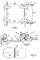
- Figure 1 shows this apparatus as applied to a car the geometric trim whereof is to be checked. Of the car, only the front wheels 1 are shown, along with the rear wheels 2 and axles 3.
- the apparatus is only schematically illustrated, and in particular there may be observed the projector lamps 4 fastened to the front wheels 1, the optics 5 of projection of the toe-in, camber, and incidence scales, the optics 6 of projection of the rear alignment cross, the panels or flags 7 for reading camber and incidence, and the mirrors 8 for transferring the toe-in scale.
- the flag for reading toe-in is not visible because hidden behind the other elements.
- To the rear wheels there are fastened graduated flags 9 for reading wheel alignment, of a known design.
- FIG 2 shows more in detail a projector lamp 4 belonging to the inventive device.
- the optics 10 for projecting the toe-in measurement scale (said scale being indicated at 11)
- an optics 12 for projecting the camber and incidence measurement scale (said scale being indicated in the figure with the reference numeral 13)
- an optics 14 for projecting a rear alignment cross To the projection assembly proper, there is secured, at one end thereof, a flag supporting staff or rod 15, the other end whereof carries the fixed flag 16 (corresponding to 7 in Figure 1'), onto which the camber and incidence measurement scale is projected, and the suspended flag 17, onto which is projected the toe-in measurement scale, after undergoing reflection by the mirror 8 associated with the projector lamp secured to the opposite wheel.
- FIG. 1 shows in detail a flag which comprises an opaque element 22 formed with a slit 23, whereat there are provided optical-electronic sensors 24, e.g. phototransistors.
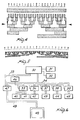
- Figures 4 and 5 show, respectively, the toe-in measurement scale and camber and incidence measurement scale.
- Both scales comprise a plurality of columns wherein light opaque regions and light transparent regions follow one another, being arranged in agreement with a given binary code, e.g. the Gray code, such that onto the flags there are projected bright and dark regions reproducing the scale patterns.
- a given binary code e.g. the Gray code
- Figure 6 shows a block diagram of the electronic circuits associated with the projectors.
- a microprocessor 30 associated with a memory 31 for the program, and with a memory 32 for the data, and wherefrom there extend an address bus 33 and data bus 34.
- an address bus 33 and data bus 34.
- To the data bus 34 there are connected five input gates 35 to 39, which receive data from the outside through input terminals 40 to 45.
- the gate 35 is connected to the terminal 40 for seleeting the measurement type and to the gate 41 for selecting the wheel rim diameters
- the input gate 36 is connected to the transducer 42 for the camber of the left-hand wheel
- the input gate 37 is connected to the transducer 43 for the toe-in of the left-hand wheel
- the gate 38 is connected to the transducer 44 for the camber of the right-hand wheel
- the gate 39 is connected to the transducer 45 for the toe-in of the right-hand wheel.
- the address bus 33 is connected to an address decoder 46 and a video interface 47, also connected to the data bus 34.
- the video interface supplies the data processed in the microprocessor 30 to a display unit 49 over the channel 48.
- the related scale 13 is projected by means of the projector lamp 4 onto the onto the flag 7 (16 in Figure 2) associated with that projector. If the wheel 1 has camber from the vertical, the projector 4 and fixed flag will also be inclined by the same angle. By contrast, the related scale can be swung and is kept in a perfectly vertical position by a pendulum system 25. Consequently, at the slit of the flag 7, there will be projected a column of the scale which is no longer the zero one but rather the one corresponding to the particular camber angle of the wheel 1. Thus, the phototransistors 24 located at the slit 23 of the flag will detect the particular sequence of white spaces and black spaces falling thereat and transfer that code to the electronic members which process it as described hereinafter.
- the related fixed scale 11 is projected onto the mirror 8 associated with the projector, and thanks to its orientation and to the fact that it keeps in the vertical position,it always reflects the beam 53 onto the flag 17 associated with the projector connected to the other wheel. If a toe-in angle other than zero exists, the related scale will be shifted with respect to the flag in a horizontal direction to the right or to the left by a distance univocally linked to the toe-in angle. Consequently, at the slit, instead of the zero column, a different column will appear, therein the particular sequence of light and dark spaces indicates the displacement. That sequence is detected by the phototransistors 24, which will feed it to the electronic circuit provided for processing that code and supplying the toe-in value in an intelligible fashion, as explained hereinafter.
- the optics 6 projects a beam, designated in the figure with the reference number 60, onto the corresponding graduated flag 9, thereby the alignment reading is obtained in a conventional manner.
- the input gate 35 is enabled which, being connected to the measurement selector 40 and diameter selector 41, supplies the microprocessor with information on the type of operations to be carried out.
- the input gate 35 supplies the types of measurements to be taken (camber, incidence, or toe-in), the diameter of the rim, if the measurement being taken preceeds or follows the adjustment.
- the input gate 35 will request the microprocessor 30 to set or clear the incidence scales and twist.
- the gates 37 and 39, or 36 and 38 are enabled to thus allow the input of the data present at the gates 42 to 45, corresponding to the phototransistors of the various flags.
- the microprocessor 30 will convert the stored information according to the Gray code into binary code information, process them according to the type of measurement taken, convert them into the ASCII code, and suitably re-locate them in the memory. Finally, the thusly processed data are transferred into the video display.
- the microprocessor 30 will algebraically add the values relative to the toe-in of the left wheel and right wheel together, and supply the display with the sum value. Thus, it is no longer required that the operator performs that computation personally prior to carrying out the re-balancing operation proper, so that his job is made easier and no errors are possible any longer.
- microprocessor may be connected to an external memory, wherein the specification data of the various cars would be stored. Such data may then be displayed directly on the video display, thus eliminating the need to always keep a manual at hand for comparison of the specification data with the actual measured values.
- the apparatus according to the invention provides fully reliable measurements and is not liable to go out of adjustment in any way, since the reading scales are digital ones and the optical-electronic sensors are to detect the sequence of white and black spaces in the column projected thereat.
- the processing of the transducer signals takes place at numerical level, and therefore, is no longer affected by problems of thermal variation or ageing.
- the apparatus of this invention is quite versatile, because through the use of a microprocessor and video display it allows memory storage of measurements, either singly or as a whole. Such measurements may then be recalled by the operator to have an overall picture of the. car trim condition, both before and after the corrections made. Future developments are also possible, such as the addition of a printer or tape recording the car specifications supplied by the manufacturers.
- the measurement scales for toe-in, camber and incidence simultaneously present, in addition to a digital section, also an analog section of conventional type for optically reading the car trim angles.
- analog scales enable the car trim to be simultaneously checked both on the screen connected to the microprocessor and on the optical scales, so that a dual form of checking becomes feasible, while affording a more reliable measurement.
- the simultaneous provision of optical scales ensures that, in the event of power outage to the microprocessor or failure in the electronic devices, the checks on the car trim can be effected all the same, e.g. by hooking up on the car battery, in any places, without requiring the screen and electronic circuit.
- the illustrated device will be advantageous over the prior art, because it does not require the time-consuming and complicated operations described in the preamble.
- the mirror is mounted on a pendulum, which enables automatic reading of toe-in and eliminates the need of shifting manually the mirror in order to align the scale on its reference, as was the case with known apparatus.
- the materials used and the dimensions may be any selected ones to suit applicational requirements.
Landscapes
- Physics & Mathematics (AREA)
- General Physics & Mathematics (AREA)
- Length Measuring Devices By Optical Means (AREA)
Applications Claiming Priority (2)
| Application Number | Priority Date | Filing Date | Title |
|---|---|---|---|
| IT2334981 | 1981-08-03 | ||
| IT23349/81A IT1194084B (it) | 1981-08-03 | 1981-08-03 | Dispositivo di controllo della geometria delle ruote |
Publications (2)
| Publication Number | Publication Date |
|---|---|
| EP0071843A2 true EP0071843A2 (de) | 1983-02-16 |
| EP0071843A3 EP0071843A3 (de) | 1984-12-19 |
Family
ID=11206312
Family Applications (1)
| Application Number | Title | Priority Date | Filing Date |
|---|---|---|---|
| EP82106669A Withdrawn EP0071843A3 (de) | 1981-08-03 | 1982-07-23 | Apparat zum überprüfen der Reifengeometrie |
Country Status (2)
| Country | Link |
|---|---|
| EP (1) | EP0071843A3 (de) |
| IT (1) | IT1194084B (de) |
Cited By (4)
| Publication number | Priority date | Publication date | Assignee | Title |
|---|---|---|---|---|
| FR2570178A1 (fr) * | 1984-09-07 | 1986-03-14 | Fmc Corp | Appareil d'alignement des roues d'un vehicule et procede associe |
| WO1987002450A1 (fr) * | 1985-10-21 | 1987-04-23 | Wild Heerbrugg Ag | Procede et dispositif pour reporter optiquement un angle entre des appareils situes a des endroits differents |
| US4761749A (en) * | 1984-09-07 | 1988-08-02 | Fmc Corporation | Vehicle wheel alignment apparatus and method |
| GB2343006A (en) * | 1998-10-22 | 2000-04-26 | Paul Nicholas Gibbs | Vehicle wheel alignment checking device |
Family Cites Families (4)
| Publication number | Priority date | Publication date | Assignee | Title |
|---|---|---|---|---|
| US3865492A (en) * | 1972-03-15 | 1975-02-11 | Bear Manufacturing Corp | Apparatus for use in aligning wheels |
| US4143970A (en) * | 1977-09-16 | 1979-03-13 | Fmc Corporation | Wheel alignment method and apparatus |
| FR2451020A1 (fr) * | 1979-03-09 | 1980-10-03 | Muller Et Cie Ets | Procede pour controler le parallelisme des roues des trains avant et arriere de vehicules automobiles et appareil pour la mise en oeuvre de ce procede |
| YU97279A (en) * | 1979-04-24 | 1983-02-28 | Bosko Skoknc | Device for measuring longitudinal and transversal plants of an axis at an automobile suspension |
-
1981
- 1981-08-03 IT IT23349/81A patent/IT1194084B/it active
-
1982
- 1982-07-23 EP EP82106669A patent/EP0071843A3/de not_active Withdrawn
Cited By (6)
| Publication number | Priority date | Publication date | Assignee | Title |
|---|---|---|---|---|
| FR2570178A1 (fr) * | 1984-09-07 | 1986-03-14 | Fmc Corp | Appareil d'alignement des roues d'un vehicule et procede associe |
| US4761749A (en) * | 1984-09-07 | 1988-08-02 | Fmc Corporation | Vehicle wheel alignment apparatus and method |
| AU581665B2 (en) * | 1984-09-07 | 1989-03-02 | Snap-On Technologies, Inc. | Vehicle wheel alignment apparatus and method |
| AU601076B2 (en) * | 1984-09-07 | 1990-08-30 | Snap-On Technologies, Inc. | Vehicle wheel alignment apparatus and method |
| WO1987002450A1 (fr) * | 1985-10-21 | 1987-04-23 | Wild Heerbrugg Ag | Procede et dispositif pour reporter optiquement un angle entre des appareils situes a des endroits differents |
| GB2343006A (en) * | 1998-10-22 | 2000-04-26 | Paul Nicholas Gibbs | Vehicle wheel alignment checking device |
Also Published As
| Publication number | Publication date |
|---|---|
| IT8123349A1 (it) | 1983-02-03 |
| IT1194084B (it) | 1988-09-14 |
| IT8123349A0 (it) | 1981-08-03 |
| EP0071843A3 (de) | 1984-12-19 |
Similar Documents
| Publication | Publication Date | Title |
|---|---|---|
| US5018853A (en) | Angle sensor with CCD | |
| US4718759A (en) | Apparatus for the alignment and balance of the wheels of a motor vehicle | |
| US4977524A (en) | Electronic measuring gauge and apparatus for accurate vehicle stance diagnosis and guidance in effecting wheel alignment | |
| US5535522A (en) | Method and apparatus for determining the alignment of motor vehicle wheels | |
| US6237234B1 (en) | Method and apparatus for measuring vehicle wheel roll radius | |
| US5675408A (en) | Device and method for the measuring of wheel angles | |
| US4690557A (en) | Arrangement for measuring wheel alignment and steering geometry in an automobile | |
| EP0460471B1 (de) | Verfahren und Vorrichtung zur Messung von Radwinkeln | |
| US4180915A (en) | Runout compensation in vehicle wheel alignment measuring apparatus | |
| JP3487726B2 (ja) | 自動車整列状態表示方法及び装置 | |
| US4729172A (en) | Process for establishing the driving direction of a vehicle with an electronic compass | |
| GB1573243A (en) | Apparatus for determining vehicle wheel alignment | |
| EP0120910B1 (de) | Spurmessung der hinteren und vorderen radsätze eines automobils | |
| US4389793A (en) | Wheel alignment apparatus | |
| US5852241A (en) | Method and device for feeding components for bone cement into a mixing vessel for these | |
| EP0071843A2 (de) | Apparat zum überprüfen der Reifengeometrie | |
| US2667805A (en) | Mirror and light beam apparatus for checking wheel alignment characteristics with correction for runout | |
| EP0533143A2 (de) | Sai und Nachlauf Kompensation für laufende Nachlauf- und Sturzablesungen | |
| CN100504284C (zh) | 用于确定机动车辆的车轮对准的设备 | |
| US4341468A (en) | Method and apparatus for diagnosing vehicle wheel alignment | |
| US20190107385A1 (en) | Bead measurement system with a movable camera | |
| EP0094999A1 (de) | Fotoelektrische Messwertgeber zur Positionsmessung | |
| US5301110A (en) | Improvements in the method and apparatus for evaluating the TOOT (toe out on turns) of steerable wheels while said steerable wheels are being aligned | |
| US2469541A (en) | Gauging instrument for vehicle wheels | |
| US4168909A (en) | Optical toe gauge with angled screens for vehicle wheels |
Legal Events
| Date | Code | Title | Description |
|---|---|---|---|
| PUAI | Public reference made under article 153(3) epc to a published international application that has entered the european phase |
Free format text: ORIGINAL CODE: 0009012 |
|
| AK | Designated contracting states |
Designated state(s): AT BE CH DE FR GB LI NL SE |
|
| PUAL | Search report despatched |
Free format text: ORIGINAL CODE: 0009013 |
|
| AK | Designated contracting states |
Designated state(s): AT BE CH DE FR GB LI NL SE |
|
| STAA | Information on the status of an ep patent application or granted ep patent |
Free format text: STATUS: THE APPLICATION IS DEEMED TO BE WITHDRAWN |
|
| 18D | Application deemed to be withdrawn |
Effective date: 19850201 |