EP0071850A1 - Production de cartes d'enregistrement magnétiques - Google Patents
Production de cartes d'enregistrement magnétiques Download PDFInfo
- Publication number
- EP0071850A1 EP0071850A1 EP82106692A EP82106692A EP0071850A1 EP 0071850 A1 EP0071850 A1 EP 0071850A1 EP 82106692 A EP82106692 A EP 82106692A EP 82106692 A EP82106692 A EP 82106692A EP 0071850 A1 EP0071850 A1 EP 0071850A1
- Authority
- EP
- European Patent Office
- Prior art keywords
- magnetic recording
- layer
- magnetic
- recording layer
- card
- Prior art date
- Legal status (The legal status is an assumption and is not a legal conclusion. Google has not performed a legal analysis and makes no representation as to the accuracy of the status listed.)
- Granted
Links
Images


Classifications
-
- G—PHYSICS
- G06—COMPUTING OR CALCULATING; COUNTING
- G06K—GRAPHICAL DATA READING; PRESENTATION OF DATA; RECORD CARRIERS; HANDLING RECORD CARRIERS
- G06K19/00—Record carriers for use with machines and with at least a part designed to carry digital markings
- G06K19/06—Record carriers for use with machines and with at least a part designed to carry digital markings characterised by the kind of the digital marking, e.g. shape, nature, code
- G06K19/06187—Record carriers for use with machines and with at least a part designed to carry digital markings characterised by the kind of the digital marking, e.g. shape, nature, code with magnetically detectable marking
- G06K19/06196—Constructional details
Definitions
- This invention relates to a magnetic recording card and a process for producing the same and more specifically to a magnetic plastic card suitable for use as credit cards, bank cards,ID cards, and the like and to a process for producing the same.
- a magnetic plastic card comprises an opaque core sheet made of a synthetic resin such as polyvinyl chloride and transparent oversheets similarly made of polyvinylchloride or like resin and covering the surfaces of the core sheet and, moreover, has a magnetic recording layer for memorizing or storing necessary information.
- This magnetic recording layer is provided on an oversheet, and a marking such as an inscription or a picture as visible information is printed on the core sheet.
- the magnetic recording layer and the visible marking are provided-in a mutually independent state.
- the color of the magnetic recording layer is generally limited to brown or dark brown.
- a method of forming a magnetic recording layer on a card which is also being practiced comprises transferring, by using a hot die of a desired shape, a magnetic recording layer on a temporary support in a planar shape corresponding to the die shape onto a card substrate by a hot-stamping technique.
- a magnetic recording layer stock in comparison with a pigment foil or metal foil used in a hot-stamping process, ordinarily is thicker and also has a higher strength. For this reason, such a magnetic recording layer stock cannot be sheared cleanly during stamping, whereby the edges of the magnetic recording layer transferred onto the card substrate are ragged and fuzzy.
- a magnetic card thus formed by hot stamping acquires a poor external appearance in which, particularly, the impression that the magnetic recording. layer has been pasted on becomes accentuated.
- the combination of the steps of carrying out a limited-depth or partial die cutting of a magnetic recording layer stock of a magnetic transfer sheet comprising a temporary support and a magnetic recording layer stock formed uniformly on the temporary support, removing the unnecessary parts thereby to form beforehand on the temporary support a magnetic recording layer of a desired shape having smooth, fair-line edges, then transferring this magnetic recording layer onto a card substrate, and imbedding this layer in the card substrate is very effective. That is, the above mentioned partial die-cutting step not only produces smoother and fairer edges than the conventional hot-stamping step but also can produce a magnetic recording layer shape of greater fineness, whereby the magnetic recording layer itself can be effectively utilized as a design pattern.
- this invention is based on the above described findings and is embodied in the following four fundamental modes of practice and in the magnetic cards produced thereby.
- a process for producing magnetic cards comprising the three steps of the above described first fundamental mode of practice and further comprising a fourth step of printing a printed layer of characters and design on the outer surface of the magnetic recording layer of the structure obtained after the third step of imbedding the magnetic recording layer and a fifth step of leveling the card surface by placing, after the fourth printing step, a press plate with a mirror-finished surface against the printed layer thus printed and heating and pressing the printed layer thereby to cause the outer surfaces of the printed layer and the card substrate to lie flush in the same plane.
- a process for producing magnetic cards which comprises the first step of the above described process embodying the first fundamental mode of practice to form the magnetic transfer sheet having the magnetic recording layer of island form and further comprises:
- a process for producing magnetic cards which comprises the four steps of the above described process embodying the third fundamental mode of practice of the invention and further comprises a fifth step of printing a printed layer of characters and design on the outer surface of the magnetic recording layer of the structure obtained by the fourth step of imbedding the magnetic recording layer and a sixth step of leveling the card surface by placing, after the fifth printing step, a press plate with a mirror-finished surface against the oversheet and heating and pressing the same thereby to cause the outer surfaces of the printed layer and the oversheet to lie in the same plane.
- magnetic cards fabricated in accordance with above stated process of the invention.
- Each of these cards is provided on at least one surface of a card substrate with a magnetic recording layer of island form formed by die cutting and having smooth, fair-line edges.
- a feature of the magnetic,card of the invention is that its magnetic recording layer is so imbedded that its outer surface lies flush in the same plane as the outer surface of the card substrate.
- the card substrate can comprise a core sheet and oversheets, as in the cards produced according to the above stated third and fourth fundamental modes of practice of the process of this invention.
- a printed layer of characters and/or design pattern can be inscribed or imbedded so that its surface will lie flush in the same plane as that of the magnetic recording layer, as in the cards produced according to above stated second and fourth fundamental modes of practice of the process of the invention.
- island form designates a physical state wherein the magnetic recording layer is formed in a position separated from the peripheral edges of the magnetic card.
- views other than perspective views and bottom views are all elevational views in vertical section taken in planes parallel to the thickness direction of the layers shown and will be referred to as sections, the upper parts of these views corresponding to the upper or front faces of the magnetic cards.
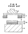
- FIGS. 1 through 4b As conducive to a full understanding of this invention, a typical example of a conventional magnetic card and a process for producing the same will first be described briefly with reference to FIGS. 1 through 4b.
- FIGS. 2 through 4b indicate the steps of a typical example of the process for forming a planar (or laminar) magnetic recording structure or piece in "island” state by a conventional hot stamping method using a magnetic transfer sheet 3 and a heating head or hot die 4.
- a magnetic transfer sheet 3 prepared by forming on a temporary support 5 a magnetic recording piece stock layer 9 comprising a separation-aiding or releasing layer 6, a colored layer 7, and a magnetizable layer 8 is superposed on a card substrate 10 so that the magnetizable layer 8 is adjacently contacting the substrate 10.
- a hot die 4 of a desired shape is pressed downward against this assembly of layers. Thereafter, the hot die 4 and the magnetic transfer -sheet 3'are lifted off the substrate 10, whereupon a portion 9a of the magnetic recording piece stock layer 9 is transferred in a shape corresponding to the hot die 4 onto the card substrate 10 because of the adhesive strength of a binder within the magnetizable layer 8 by which it adheres to the substrate 10 as indicated in FIG. 3, the releasing layer 6 of this portion 9a separating away from the temporary support 5.
- the magnetic recording layer 9a is heated and pressed and is thus forced to be imbedded in the card substrate 10, the upper surfaces of the layer 9a and the substrate becoming flush as indicated in FIGS. 4a and 4b, whereupon a magnetic card BB is obtained.
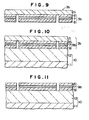
- a magnetic transfer sheet 3 in which a magnetic recording layer stock 9 comprising a releasing layer 6, a colored layer 7, and a magnetizable layer 8 is formed on a temporary support 5 is prepared.
- a partial or limited-depth, die-cutting process step is carried out so as to cut the magnetic recording layer stock 9 but not to cut the temporary support 5 by means of a cutting die (not shown) of a desired shape thereby to form in the magnetic recording layer stock 9 a partial cut line 21 of a loop or closed figure corresponding to the desired island form.
- the surplus portion of the layer stock outside of the partial cut line 21 is cut away and removed and a magnetic transfer sheet 3b, as shown in FIGS. 8 and 9, in which a magnetic recording layer or piece 9b of island form is left remaining is formed.
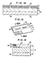
- This transfer sheet 3a thus obtained is superposed, as indicated in FIG. 10, on the oversheet 12 of a card substrate 10 comprising a core sheet 11 and the oversheet 12 and is then heated by suitable heating means such as heating plates (not shown). Then, by peeling off the temporary support 5, the magnetic recording layer 9b of island form is transferred onto the oversheet 12 of the card substrate as indicated in FIG. 11. The magnetic recording layer 9b on the substrate 10 is then heated and pressed by press plates (not shown) having a mirror-finished surface thereby being imbedded in the card substrate 10, until the upper surfaces of the magnetic recording layer 9b and of the substrate 10 are flush, that is, lie in the same plane, as indicated in FIG. 1 2 .
- FIGS. 12 and 14 are sections respectively corresponding to views in the directions of lines D-D and E-E in FIG. 13.
- a feature of a magnetic card produced in the above described manner according to this invention is that the edges of its magnetic recording layer 9b are very smooth, fair, and definite in com- parison with those of the aforedescribed conventional card.
- the magnetic card CC as shown in FIGS. 13 and 14, has an ordinarily printed layer 23 for displaying visible information in harmony with the pattern of the magnetic recording layer 9b (that is, not concealed thereby or being of such a color or pattern that the concealment by the magnetic recording layer will not be harmful.)
- This visible information layer 23 is formed beforehand in accordance with an ordinary card printing process on the core sheet 11. In FIGS. 10, 11, and 12, this layer 23 is omitted for the purpose of brevity.
- the core sheet 11 white opaque polyvinyl chloride, for example, can be used.
- the oversheets 12 transparent polyvinyl chloride, for example, can be used.
- the oversheets 12 can be bonded by heat fusion onto the opposite surfaces of the core sheet 11, or the oversheets 12 and the core sheet can be tentatively secured together with an adhesive at parts thereof other than the forming part of the final product card to obtain a laminated structure which is used as the card substrate 10.
- the tentatively secured core sheet 11 and the oversheets 12 are formed into an integral card substrate in the transfer step or in the heating and pressing step for imbedding the magnetic recording layer 9b.
- the temporary support 5 is made of a sheet of a thickness of the order of 25 to 100 ⁇ m of a polymer such as polyester, polyethylene,.- polypropylene, or polycarbonate.
- the releasing layer 6 is obtained by coating the temporary support 5 with a paint comprising a resin such as an acrylic ester resin or a rosin derivative resin to a coating thickness (dried) of 0.2 to 2 u. As described hereinafter, this releasing layer 6 is not indispensible in all cases but is preferably used for carrying out the transfer step smoothly and for protecting the colored layer 7 and the magnetizable layer 8.
- the colored layer 7 is provided for the purposes of concealing the color of the magnetizable layer 8 and of utilizing the magnetic recording layer 9b positively and aesthetically and is preferably provided except where the color of the magnetizable layer 8 itself is desirable, or where the color of the magnetizable layer 8 has a cryptic color relation to the color of the surrounding card substrate.
- This colored layer 7 is obtained by coating the releasing layer 6 with a coloring paint prepared by dispersing a desired coloring matter (pigment or dyestuff) in a binder having as its predominant ingredient a thermoplastic resin such as a vinyl chloride-vinyl acetate copolymer, an acrylic resin, or a cellulose derivative resin, the coloring paint being applied by a gravure coating method, a roll coating method, or like suitable method to a coating thickness of 0.5 to 10 ⁇ (dried). It is desirable that this colored layer 7 be thin when the electric-magnetic conversion characteristics are considered. On the other hand, when the hue is considered, a thick colored layer 7 is desirable, in general. Accordingly, this thickness should be determined in view of the magnetization process apparatus, standards, and other pertinent conditions.
- the magnetizable layer 8 is formed by applying by the roll coating method or some other effective method a magnetic paint prepared by dispersing a magnetic powder of ⁇ -Fe 2 O 3 , Co-Fe304, CrO 2 , or the like in a binder having as its predominant ingredient a thermoplastic resin such as a vinyl chloride - vinyl acetate copolymer, a cellulose derivative resin, or a vinyl chloride resin, the magnetic paint being applied as a coating of a thickness of approximately 5 to 25 ⁇ (dried).
- a magnetic paint prepared by dispersing a magnetic powder of ⁇ -Fe 2 O 3 , Co-Fe304, CrO 2 , or the like in a binder having as its predominant ingredient a thermoplastic resin such as a vinyl chloride - vinyl acetate copolymer, a cellulose derivative resin, or a vinyl chloride resin, the magnetic paint being applied as a coating of a thickness of approximately 5 to 25 ⁇ (dried).
- the cutting die used for the partial die cutting of the magnetic recording layer can be of any type provided that it has a closed-figure shape for producing the desired island shape and has ample hardness and sharpness for die cutting of plastics.
- the partial die cutting can be effectively carried out by means of, for example, a seal-printing die-cutting press.
- the transfer of the magnetic recording layer 9b of island shape can be carried out, for example, by using a hot die (not shown) of dimensions somewhat greater than those of the magnetic recording layer of island shape to apply heat and pressure under the conditions of a heating temperature of 150 to 200°C, a pressure of 50 to 250 kg/cm , and an application time of 0.5 to 2 seconds thereby to cause the magnetic recording layer 9b to adhere to the card substrate 10.
- the press plate (not shown) used for imbedding the magnetic recording layer 9b thus transferred into the card substrate 10 is, for example, a stainless-steel plate of 0.5-mm thickness having a mirror-finished surface.
- the heating and pressing conditions for this imbedding step are, for example, a heating temperature of 120 to 180°C, a pressure of 10 to 50 kg/cm 2 , and a process time of 5 to 30 seconds.
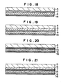
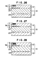
- the magnetic transfer sheets shown in FIGS. 15 through 25 are obtained by respectively changing the combinations of the temporary support 5 and the magnetizable layer 8, which are indispensible elements, and, in addition according to necessity, the releasing layer 6, the colored layer 7, a nonmagnetic metal layer 15, and a heat-sensitive adhesive layer 16.
- the releasing layer 6 and the colored layer 7 are as described hereinbefore.
- the nonmagnetic metal layer 15 of thin film thickness effectively conceals the magnetizable layer 8 and is provided according to necessity for the purpose of imparting a good hue by merely providing a relatively thin colored layer 7 on this nonmagnetic metal layer 15, while retaining good electric-magnetic conversion characteristics.
- This layer 15 is formed by vapor deposition of, for example, aluminum, tin, or the like to 0 a thickness of _the order of 500 A, for example.
- a beautiful coloring can be amply imparted with a thickness of the colored layer 7 of 0.5 to a number of ⁇ .
- the heat-sensitive adhesive layer 16 is provided when necessary for imparting good heat transferability of the magnetic transfer sheet relative to the card substrate while retaining a high concentration of magnetic particles in the magnetizable layer 8 and therefore retaining good magnetic characteristics.
- a layer containing a thermoplastic resin such as an acrylic resin or a vinyl chloride-vinyl acetate copolymer as its predominant ingredient and having a thickness of the order of 1 to 15 ⁇ is used.
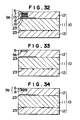
- the structure shown in FIG. 12 is first prepared according to the first fundamental mode of practice. Then, as shown in FIG. 37, a printed lettering layer 24 of a thickness of 1 to 20 u (dried) is formed by a process such as silk-screen printing on the magnetic recording layer 9b imbedded in the card substrate 10 of the structure thus prepared.
- the material constituting this printed lettering layer 24 is substantially the same as that of the colored layer 7. If this printed, lettering layer 24 is excessively thick, it will affect the electric-magnetic conversion characteristics and give rise to a great drop in the output. For this reason, it is desirable that this layer 24 be made as thin as possible without losing its desired display effect.
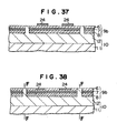
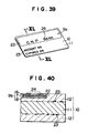
- this printed lettering layer 24 is imbedded into the magnetic recording layer 9b, and a structure as shown in FIG. 38 wherein the upper surfaces of the card substrate 10, the magnetic recording layer 9b, and the printed lettering layer 24 all lie flush in the same plane is obtained. Then, by cutting this structure along the planes indicated by lines F-F, a magnetic card as shown in FIGS. 39 and 40 is obtained.
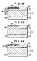
- magnetic cards of modified structures shown in FIGS. 41 through 51 can be obtained by using magnetic transfer sheets of the structures shown in FIGS. 15 through 25, respectively, in place of that shown in FIG. 5.
- the magnetic recording layer 9b not only is caused to contribute, itself, to the aesthetic appearance of the card as a pattern but also affords an area for forming an additional pattern such as a printed layer of characters and/or a picture pattern.
- an additional pattern such as a printed layer of characters and/or a picture pattern.
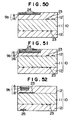
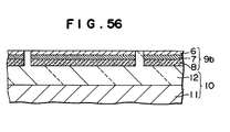
- the third fundamental mode of practice of the process of this invention for producing magnetic cards is a repetition of the aforedescribed first fundamental mode with the use of an oversheet 12 instead of a card substrate 10 comprising a laminated structure of a core sheet 11 and oversheets 12. More specifically, in accordance with the first fundamental mode, the magnetic transfer sheet 3b shown in FIG. 9 is superposed on an oversheet 12 (FIG. 53), and after heating, the temporary support 5 is peeled off to transfer the magnetic recording layer 9b in island form onto the oversheet 12 (FIG. 54).
- FIG. 56 The structure thus obtained as shown in FIG. 56 is essentially the same as the structure shown in FIG. 12. By subsequently cutting this structure similarly as in the first fundamental mode of practice, a magnetic card similar to that shown in FIGS. 13 and 14 is obtained.
- a printed layer 24 of characters and/or a picture pattern is formed on the magnetic recording layer 9b as indicated in FIGS. 37 and 38 in the second fundamental mode of practice. Then, with the use of a press plate of mirror-finish surface, the structure is heated and pressed so that the upper surface of the printed layer 24 of characters and/or a picture pattern lies flush in the same plane as those of the magnetic recording layer 9b and the card substrate 10.
- a magnetic card produced by this fourth fundamental mode of practice is identical to that produced by the aforedescribed second fundamental mode of practice.
- the structures as indicated in FIGS. 39 through 51 can be obtained.
- a temporary support comprising a polyester film of 50-u thickness was coated with a paint of an acrylic ester resin to a coating thickness of 0.5 ⁇ by a gravure coating process thereby to form a releasing layer.
- This layer was then coated with a coloring paint to a coating thickness of 2 p by a gravure coating process, the coloring paint comprising a vinyl chloride-vinyl acetate copolymer as a principal binder and a desired coloring matter dispersed therein.
- a coloring paint comprising a vinyl chloride-vinyl acetate copolymer as a principal binder and a desired coloring matter dispersed therein.
- This colored layer was then coated with a magnetic paint to a coating thickness of 15 ⁇ by a roll coating process, the magnetic paint comprising a vinyl chloride-vinyl acetate copolymer as a principal binder and magnetic powder particles of y-Fe 2 0 3 dispersed therein.
- the magnetic paint comprising a vinyl chloride-vinyl acetate copolymer as a principal binder and magnetic powder particles of y-Fe 2 0 3 dispersed therein.
- a card substrate was fabricated by laminating oversheets oftransparent polyvinyl chloride of a thickness of 0.1 mm on the front and back surfaces of a core sheet of bluish white polyvinyl chloride on the front and back faces of which patterns had been printed by offset printing.
- the above described magnetic transfer sheet was placed on this card substrate at a desired position thereof and was heated and pressed against the card substrate with a hot die, which was one size larger than the shape of the magnetic recording layer of island form, under the conditions of a temperature of 180°C, a pressure of 100 kg/cm 2 , and a process time of 0 .5 second.
- the polyester film was peeled off thereby to transfer the magnetic recording layer onto the card substrate (FIG. 11).
- the laminated structure thus formed was clamped between stainless-steel plates of 0.5-mm thickness which had been mirror finished and was heated and pressed under the conditions of 150°C and 25 kg/cm 2 for 20 minutes. After cooling, a card structure in which the oversheets and the core.sheet had been heat fused and laminated was obtained, and the desired magnetic plastic card, as shown in FIGS. 13 and 14, having a magnetic recording layer of island form, which had been imbedded in the card substrate so that their outer surfaces lay flush in the same plane, was obtained.
- a temporary support comprising a polyester film of 50- ⁇ thickness was coated to a coating thickness of 0.5 u with a paint of an acrylic ester by a gravure coating process thereby to form a releasing layer.
- a coloring paint comprising a vinyl chloride-vinyl acetate copolymer as a principal binder and a desired coloring matter dispersed therein was applied as a coating of a thickness of 2 ⁇ by a gravure coating process thereby to form a colored layer.
- This colored layer was coated to a coating thickness of 15 ⁇ with a magnetic paint by a roll coating process, the magnetic paint comprising a vinyl chloride-vinyl acetate copolymer as a principal binder and powder particles of y-Fe 2 0 3 dispersed therein.
- a magnetizable layer was formed.
- a varnish having an acrylic resin as a predominant component was applied as - an adhesive coating layer of a thickness of 10 ⁇ by a roll coating process, whereupon a magnetic transfer sheet as shown in FIG..19 was obtained.
- Example 2 With the use of this.magnetic transfer sheet, the procedures of Example 1 were followed to carry out partial die cutting, removal of superfluous parts of the magnetic recording layer, transferring of the magnetic recording layer, and heating and pressing.
- the magnetic recording layer of island form was thus imbedded within the card substrate so that its outer surface lay flush in the same plane as that of the card substrate.
- the desired magnetic plastic card as shown in FIG. 30, having a magnetic recording layer of island form was obtained.
- a temporary support comprising a polyester film of 50- ⁇ thickness was coated to a coating thickness of 0.5 p with a paint comprising an acrylic ester resin by a gravure coating process thereby to form a releasing layer.
- a coloring paint comprising a vinyl chloride-vinyl acetate copolymer as a principal binder and a desired coloring matter dispersed therein, which was applied by a roll coating process.
- a colored layer was thus formed.
- a magnetic paint comprising a vinyl chloride-vinyl acetate copolymer as a principal binder and powder particles of y-Fe 2 0 3 dispersed therein was applied as a coating of 15-u thickness by a roll coating process thereby to form a magnetizable layer (FIG. 5).
- the pitch or spacing interval with which the partial die cutting of the magnetic transfer sheet was made the same as the pitch of the multiple repeated pattern printed in succession on the core sheet.
- the above described magnetic transfer sheet was then superposed on an oversheet for surface purpose, and heat transferring was carried out under the conditions of a heating temperature of 180°C, a speed of 5 meters/min., and a pressure of 10 kg/30 cm2as indicated in FIGS. 53 and 54.
- oversheet was then tentatively secured (with an adhesive at parts outside of the finished product) in register with a desired position with respect to the pattern of the core sheet which had been offset printed, and on the back face, also, a transparent oversheet was similarly secured tentatively as indicated in FIG. 55.
- the structure thus formed was clamped between stainless-steel plates of 0.5-mm thickness with mirror-finished surfaces and was heated and pressed under the conditions of 150°C and 25 kg/cm 2 for 20 minutes. After this structure was cooled, a card structure in which the oversheet and the core sheet had been laminated by heat fusion was obtained, and a magnetic plastic card as shown in FIGS. 13 and 14 having a magnetic recording layer of a desired island form whose outer surface lay flush in the some plane as that of the card substrate was obtained.
- the aforedescribed card substrate was again clamped between stainless-steel plates of 0.5-mm thickness with mirror-finished surfaces, heated and pressed under the conditions of 150°C and 25 kg/cm2 for 20 minutes, and cooled.
- the printed layer of the characters and design was imbedded within the magnetic recording layer, and a magnetic plastic card having a magnetic recording layer of island form with desired characters and designs, in which the outer surfaces of the card substrate, the magnetic recording layer, and the printed layer of the characters and design lay flush in the same plane, was obtained.
- a temporary support comprising a polyester film of 50- ⁇ thickness was coated to a coating thickness .of 0.5 ⁇ with a paint comprising an acrylic ester resin by a gravure coating process thereby to form a releasing layer.
- a coloring paint comprising a vinyl chloride-vinyl acetate copolymer as a principal binder and a desired coloring matter dispersed therein, which paint was applied by a gravure coating process. A colored layer was thus formed.
- This aluminum layer was further coated to a coating thickness of 15 ⁇ with a magnetic paint comprising a vinyl chloride-vinyl acetate copolymer as a principal binder and fine particles of y-Fe 2 0 3 dispersed therein, the magnetic paint being applied by a roll coating process.
- a magnetic transfer sheet having a magnetizable layer (FIG. 17) was thus formed.
- magnetic plastic cards each having magnetic recording layer of island form containing a pattern, were respectively produced by procedures according to Examples 1, 3, 4 and 5 (FIGS. 28, 43 and 47).
- the rate of decrease of output due to the effect of the printed layer of characters and design in the electric-magnetic conversion characteristics of each of the cards produced according to Examples 1 through 6 was within 10 percent at a magnetic writing-in density of 210 FRPI, which was-of an order well within allowable limits.
Landscapes
- Physics & Mathematics (AREA)
- General Physics & Mathematics (AREA)
- Engineering & Computer Science (AREA)
- Theoretical Computer Science (AREA)
- Magnetic Record Carriers (AREA)
- Credit Cards Or The Like (AREA)
- Manufacturing Of Magnetic Record Carriers (AREA)
- Paints Or Removers (AREA)
Applications Claiming Priority (2)
| Application Number | Priority Date | Filing Date | Title |
|---|---|---|---|
| JP11622881A JPS5819740A (ja) | 1981-07-24 | 1981-07-24 | 磁気カ−ド及びその製造方法 |
| JP116228/81 | 1981-07-24 |
Publications (2)
| Publication Number | Publication Date |
|---|---|
| EP0071850A1 true EP0071850A1 (fr) | 1983-02-16 |
| EP0071850B1 EP0071850B1 (fr) | 1986-06-04 |
Family
ID=14681998
Family Applications (1)
| Application Number | Title | Priority Date | Filing Date |
|---|---|---|---|
| EP19820106692 Expired EP0071850B1 (fr) | 1981-07-24 | 1982-07-23 | Production de cartes d'enregistrement magnétiques |
Country Status (5)
| Country | Link |
|---|---|
| EP (1) | EP0071850B1 (fr) |
| JP (1) | JPS5819740A (fr) |
| KR (1) | KR880002210B1 (fr) |
| CA (1) | CA1186003A (fr) |
| DE (1) | DE3271545D1 (fr) |
Cited By (2)
| Publication number | Priority date | Publication date | Assignee | Title |
|---|---|---|---|---|
| EP0270812A3 (en) * | 1986-11-12 | 1989-08-09 | Gao Gesellschaft Fur Automation Und Organisation Mbh | Identification cards with a colour-covered magnetic track, and method of manufacturing them |
| EP1376547A4 (fr) * | 2001-03-30 | 2006-02-08 | Dainippon Ink & Chemicals | Support d'enregistrement magnetique |
Families Citing this family (4)
| Publication number | Priority date | Publication date | Assignee | Title |
|---|---|---|---|---|
| JPS61117732A (ja) * | 1984-11-12 | 1986-06-05 | Dainippon Printing Co Ltd | 磁気カ−ド |
| US4961893A (en) * | 1988-04-28 | 1990-10-09 | Schlumberger Industries | Method for manufacturing memory cards |
| JP2002140815A (ja) * | 2000-08-25 | 2002-05-17 | Dainippon Printing Co Ltd | 磁気記録媒体及びその作製方法 |
| JP6074913B2 (ja) * | 2012-05-14 | 2017-02-08 | 凸版印刷株式会社 | 表示体 |
Citations (5)
| Publication number | Priority date | Publication date | Assignee | Title |
|---|---|---|---|---|
| FR2139347A5 (fr) * | 1971-05-07 | 1973-01-05 | Matsumoto Shigeharu | |
| FR2161663A5 (fr) * | 1971-11-17 | 1973-07-06 | Mac Corquodale Ltd | |
| FR2230262A5 (en) * | 1973-05-18 | 1974-12-13 | Graphoplex Sa | Magnetic type credit card, and fabrication - presents flat surface to reading head, reducing rate of head wear |
| US4132350A (en) * | 1976-11-24 | 1979-01-02 | Dai Nippon Insatsu Kabushiki Kaisha | Magnetic card |
| GB2060487A (en) * | 1979-09-17 | 1981-05-07 | Kenrick & Jefferson Ltd | Magnetic stripe |
Family Cites Families (1)
| Publication number | Priority date | Publication date | Assignee | Title |
|---|---|---|---|---|
| JPS5827887B2 (ja) * | 1976-02-13 | 1983-06-13 | 富士写真フイルム株式会社 | 感光層を有する磁気記録媒体 |
-
1981
- 1981-07-24 JP JP11622881A patent/JPS5819740A/ja active Granted
-
1982
- 1982-07-23 EP EP19820106692 patent/EP0071850B1/fr not_active Expired
- 1982-07-23 KR KR8203288A patent/KR880002210B1/ko not_active Expired
- 1982-07-23 DE DE8282106692T patent/DE3271545D1/de not_active Expired
- 1982-07-23 CA CA000407928A patent/CA1186003A/fr not_active Expired
Patent Citations (5)
| Publication number | Priority date | Publication date | Assignee | Title |
|---|---|---|---|---|
| FR2139347A5 (fr) * | 1971-05-07 | 1973-01-05 | Matsumoto Shigeharu | |
| FR2161663A5 (fr) * | 1971-11-17 | 1973-07-06 | Mac Corquodale Ltd | |
| FR2230262A5 (en) * | 1973-05-18 | 1974-12-13 | Graphoplex Sa | Magnetic type credit card, and fabrication - presents flat surface to reading head, reducing rate of head wear |
| US4132350A (en) * | 1976-11-24 | 1979-01-02 | Dai Nippon Insatsu Kabushiki Kaisha | Magnetic card |
| GB2060487A (en) * | 1979-09-17 | 1981-05-07 | Kenrick & Jefferson Ltd | Magnetic stripe |
Cited By (3)
| Publication number | Priority date | Publication date | Assignee | Title |
|---|---|---|---|---|
| EP0270812A3 (en) * | 1986-11-12 | 1989-08-09 | Gao Gesellschaft Fur Automation Und Organisation Mbh | Identification cards with a colour-covered magnetic track, and method of manufacturing them |
| EP1376547A4 (fr) * | 2001-03-30 | 2006-02-08 | Dainippon Ink & Chemicals | Support d'enregistrement magnetique |
| US7344073B2 (en) | 2001-03-30 | 2008-03-18 | Dainippon Ink And Chemicals, Inc. | Magnetic recording medium |
Also Published As
| Publication number | Publication date |
|---|---|
| JPS5819740A (ja) | 1983-02-04 |
| JPH0222445B2 (fr) | 1990-05-18 |
| KR880002210B1 (ko) | 1988-10-18 |
| DE3271545D1 (en) | 1986-07-10 |
| EP0071850B1 (fr) | 1986-06-04 |
| CA1186003A (fr) | 1985-04-23 |
Similar Documents
| Publication | Publication Date | Title |
|---|---|---|
| JPS6018949Y2 (ja) | カ−ド | |
| US4132350A (en) | Magnetic card | |
| JP4607414B2 (ja) | 上張りされた箔上にグラフィックを有する商取引カードの製法および該製法によって製造されたカード | |
| US4376006A (en) | Magnetic recording structure | |
| US5720500A (en) | Plastic card provided with magnetic stripe | |
| US4499126A (en) | Plastic relief card having metallic luster | |
| EP0071850B1 (fr) | Production de cartes d'enregistrement magnétiques | |
| JPH0630960B2 (ja) | 感熱磁気記録媒体 | |
| US5439755A (en) | Magnetic recording medium comprising a magnetic recording layer, an intermediate layer, a metallic thermal recording layer and a protective layer | |
| US5667876A (en) | Informative card made of sheet metal | |
| US20030096073A1 (en) | Metalized label and the method of manufacture | |
| JPS6183572A (ja) | ホログラム入磁気転写シ−ト | |
| US5525569A (en) | Self-contained transfer tape | |
| JPH0812534B2 (ja) | 磁気カード | |
| JPS6334100Y2 (fr) | ||
| JP2533033B2 (ja) | ホログラム転写シ―ト | |
| JPS61117732A (ja) | 磁気カ−ド | |
| JPH0441455Y2 (fr) | ||
| JPH0114477Y2 (fr) | ||
| JP4408337B2 (ja) | 磁気カードと磁気カードの製造方法 | |
| JPH0621731Y2 (ja) | 画像形成体 | |
| JPH0473193A (ja) | 感熱磁気記録媒体及びその製造方法 | |
| JPH056255B2 (fr) | ||
| JPS6144879Y2 (fr) | ||
| JPS61117731A (ja) | 磁気カ−ド |
Legal Events
| Date | Code | Title | Description |
|---|---|---|---|
| PUAI | Public reference made under article 153(3) epc to a published international application that has entered the european phase |
Free format text: ORIGINAL CODE: 0009012 |
|
| AK | Designated contracting states |
Designated state(s): DE FR GB |
|
| 17P | Request for examination filed |
Effective date: 19830808 |
|
| RAP1 | Party data changed (applicant data changed or rights of an application transferred) |
Owner name: DAI NIPPON INSATSU KABUSHIKI KAISHA |
|
| GRAA | (expected) grant |
Free format text: ORIGINAL CODE: 0009210 |
|
| AK | Designated contracting states |
Kind code of ref document: B1 Designated state(s): DE FR GB |
|
| REF | Corresponds to: |
Ref document number: 3271545 Country of ref document: DE Date of ref document: 19860710 |
|
| ET | Fr: translation filed | ||
| PLBE | No opposition filed within time limit |
Free format text: ORIGINAL CODE: 0009261 |
|
| STAA | Information on the status of an ep patent application or granted ep patent |
Free format text: STATUS: NO OPPOSITION FILED WITHIN TIME LIMIT |
|
| 26N | No opposition filed | ||
| PGFP | Annual fee paid to national office [announced via postgrant information from national office to epo] |
Ref country code: FR Payment date: 19940610 Year of fee payment: 13 |
|
| PGFP | Annual fee paid to national office [announced via postgrant information from national office to epo] |
Ref country code: GB Payment date: 19940615 Year of fee payment: 13 |
|
| PGFP | Annual fee paid to national office [announced via postgrant information from national office to epo] |
Ref country code: DE Payment date: 19940721 Year of fee payment: 13 |
|
| PG25 | Lapsed in a contracting state [announced via postgrant information from national office to epo] |
Ref country code: GB Effective date: 19950723 |
|
| GBPC | Gb: european patent ceased through non-payment of renewal fee |
Effective date: 19950723 |
|
| PG25 | Lapsed in a contracting state [announced via postgrant information from national office to epo] |
Ref country code: DE Effective date: 19960402 |
|
| PG25 | Lapsed in a contracting state [announced via postgrant information from national office to epo] |
Ref country code: FR Effective date: 19960430 |
|
| REG | Reference to a national code |
Ref country code: FR Ref legal event code: ST |
|
| REG | Reference to a national code |
Ref country code: FR Ref legal event code: ST |
|
| REG | Reference to a national code |
Ref country code: FR Ref legal event code: ST |