EP0071884A1 - Lagereinrichtung für Lasten mit starrem Boden - Google Patents
Lagereinrichtung für Lasten mit starrem Boden Download PDFInfo
- Publication number
- EP0071884A1 EP0071884A1 EP82106827A EP82106827A EP0071884A1 EP 0071884 A1 EP0071884 A1 EP 0071884A1 EP 82106827 A EP82106827 A EP 82106827A EP 82106827 A EP82106827 A EP 82106827A EP 0071884 A1 EP0071884 A1 EP 0071884A1
- Authority
- EP
- European Patent Office
- Prior art keywords
- rails
- carriage
- installation according
- storage
- transporter
- Prior art date
- Legal status (The legal status is an assumption and is not a legal conclusion. Google has not performed a legal analysis and makes no representation as to the accuracy of the status listed.)
- Granted
Links
- 238000003860 storage Methods 0.000 claims description 26
- 238000009434 installation Methods 0.000 claims description 19
- 238000005096 rolling process Methods 0.000 claims description 8
- 238000000151 deposition Methods 0.000 claims 1
- 230000000284 resting effect Effects 0.000 claims 1
- 238000009825 accumulation Methods 0.000 description 1
- 230000000712 assembly Effects 0.000 description 1
- 238000000429 assembly Methods 0.000 description 1
- 239000011230 binding agent Substances 0.000 description 1
- 239000000470 constituent Substances 0.000 description 1
- 238000010276 construction Methods 0.000 description 1
- 230000003028 elevating effect Effects 0.000 description 1
- 238000009432 framing Methods 0.000 description 1
- 239000007788 liquid Substances 0.000 description 1
- 238000004519 manufacturing process Methods 0.000 description 1
- 239000002184 metal Substances 0.000 description 1
- 238000000034 method Methods 0.000 description 1
- 210000000056 organ Anatomy 0.000 description 1
- 239000000523 sample Substances 0.000 description 1
- 230000008685 targeting Effects 0.000 description 1
Images




Classifications
-
- B—PERFORMING OPERATIONS; TRANSPORTING
- B65—CONVEYING; PACKING; STORING; HANDLING THIN OR FILAMENTARY MATERIAL
- B65G—TRANSPORT OR STORAGE DEVICES, e.g. CONVEYORS FOR LOADING OR TIPPING, SHOP CONVEYOR SYSTEMS OR PNEUMATIC TUBE CONVEYORS
- B65G1/00—Storing articles, individually or in orderly arrangement, in warehouses or magazines
- B65G1/02—Storage devices
- B65G1/04—Storage devices mechanical
- B65G1/0407—Storage devices mechanical using stacker cranes
- B65G1/0414—Storage devices mechanical using stacker cranes provided with satellite cars adapted to travel in storage racks
-
- B—PERFORMING OPERATIONS; TRANSPORTING
- B65—CONVEYING; PACKING; STORING; HANDLING THIN OR FILAMENTARY MATERIAL
- B65G—TRANSPORT OR STORAGE DEVICES, e.g. CONVEYORS FOR LOADING OR TIPPING, SHOP CONVEYOR SYSTEMS OR PNEUMATIC TUBE CONVEYORS
- B65G1/00—Storing articles, individually or in orderly arrangement, in warehouses or magazines
- B65G1/02—Storage devices
- B65G1/04—Storage devices mechanical
- B65G1/06—Storage devices mechanical with means for presenting articles for removal at predetermined position or level
- B65G1/065—Storage devices mechanical with means for presenting articles for removal at predetermined position or level with self propelled cars
Definitions
- the object of the invention is an installation which minimizes the space occupied while allowing convenient and automatic handling.
- a storage structure made up of metallic load-bearing elements in the form of ladders braced by metal or smooth beams, providing a storage volume on several levels, extending along at least two parallel shelves separated by a circulation span, each of them offering a parallel series of storage channels ; an elevating device to bring the loads to the desired level; a transporter trolley ensuring the circulation of the loads from the ground to the spans and equipped with a turntable; an automated trolley receiving the loads directly, conveyed by the transporter trolley and able from the spans to advance inside the storage channels formed between the levels of the ladder bars .
- each of these constituents has specific characteristics.
- the automatic rail and guide rails also serve directly as support for the stored loads, which solves the problem of the play to be left between the automatic machine and the loads as well as between the PLC and the structure.
- the beams assembling the ladders together, located on the side of the span, are arranged in hollow profiles serving as running rails at the transporter trolley.
- the automated carriage carries the loads at the ends of the fork arms advancing in front of the carriage, these arms being able to take both an upward or downward movement combined with a backward or forward movement, which allows you to pick up or deposit loads and tighten them one after the other.
- the lifting device is enclosed inside a cage linked to the storage structures in such a way that this cage absorbs the longitudinal forces of the span tracks, this cage also serving to guide and carry a nacelle. cart lift.
- Such an installation is modular and expandable, it makes it possible to increase the storage volume in height, in length and in width, it can comprise one or more elevators each with one or more trolleys; a carriage can be assigned to each level, the entrances and exits being done respectively at the end of the span by two different elevators.
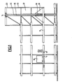
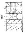
- the installation shown comprises a storage structure generally formed of planar, crossed elements, in the form of ladders 1, interconnected by beams or heddles 2.
- Each heald 2 supports bars 3 which form rails of rolling for the automated trolley, as well as the support for pallets or storage containers, as will be indicated below, the spacing of the ladders corresponding to the width of a storage channel.
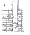
- the structure comprises two shelving assemblies 4, 5 separated by a span 6 allowing the circulation of a transporter carriage 70
- the latter is supported between two edge rails 8 formed by U-shaped profiles and in which the rollers 9 engage.
- the transporter trolley receives the automated trolley 10 on a fork on which the load 11 is placed.
- the carriage 10 can penetrate inside the channels 35 to deposit the pallets with the loads, directly on the bars 3, or take them up.
- the storage structure offers, as shown, a number of stages, the channels 35 thus being superimposed.
- the structure includes a lifting device 12, the cage 13 of which is an integral part of the storage structure and cooperates in its stability.
- Two pylons 14 each carry a guide rail 15 for a nacelle 16 which receives the transporter car.
- the cage of rectangular shape, produced by vertical braced uprights, is linked to each stage by fittings to the bars 3 forming the rails of the transporter carriage and to the heddles 8, and it thus ensures its longitudinal stability.
- the nacelle 16 has a floor 17 supported by uprights 18 framing the rail 15. Rollers 19 carried by the uprights provide guidance and rolling.
- a winch 20 and its cable move the nacelle to bring it to the desired level.
- the nacelle is provided with guide and rolling rails 22 having the same profile as the heddles 8, so that when arriving on the floor the transporter truck can leave the nacelle and enter the span.
- the elevator cage communicates with an access and exit track on which the automated trolley can engage to receive or allow the charge collection.
- a tilting stop 21 controlled by a cam of the elevator makes it possible to lock the passage of the track 8 when the nacelle is not at its level.
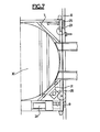
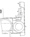
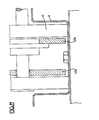
- FIGS 6 and 7 show in more detail the construction of the transporter 7 and the turntable it carries.
- the carriage 7 consists of a chassis carrying the rollers 9 circulating in the rails 8 fixed on the storage structure, as well as guide rollers 23 bearing against the bottom of the profile 8.
- the rear rollers 9 are driven in rotation by a motor 24, while the front rollers 25 are mounted idly.
- the chassis of the carriage 7, of generally square shape, also carries the turntable 30 by rollers 26 which engage in a circular profile 27.
- the carriage 7 also carries a motor 29 for driving the rotary table 30 in rotation, by means of an endless chain 310
- the table carries rails 32 having the same spacing and same profile as the bars 3, so that the automated carriage can pass from the rails 32 on the rails 3 to enter the channels 4.
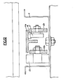
- the following figures 8 to 12 are more particularly intended to illustrate the automated carriage 10 on which the load is placed, at the entrance to the elevator, and which must deposit it in a storage channel on the rails 3.
- This carriage 10 is provided at the rear with a box 40, and is provided at its lower part with rollers 41; it comprises two arms, extending forward, each consisting of two parallel beams 42a, 42b. These arms also carry rollers 43 and are located inside the rail 3 in the shape of an omega. Between the arms is a fork, more particularly intended to receive the loads.
- This fork 44 is fixed at the rear on a stirrup 45, while at the front it has two arms 44a, 44b formed by T-sections, also advancing inside the rails 3 in the form of omega, each of them carrying a cam 46 cooperating with a roller 47 carried by one of the arms 42.
- the arms of the fork can then descend below the level of the running rails 3, so as to deposit the load thereon or , on the contrary, to pass under the load to lift it.
- This movement is controlled by a jack 48 whose rod is coupled to the fork, so that the latter, inclined relative to the axis of the carriage, takes a movement back and forth or vice versa, combined with an upward movement and descent driven by the cam 46, the profile of which has two heights, the smallest corresponding to the low position of the fork.
- the carriage carries a motor 49 driving the rollers 41 by a chain, and a cable reel for the electrical connection with the transporter carriage; it also carries a hydraulic unit 50, supplying pressurized liquid to the lifting cylinder.
- Front probes are also provided determining the location of the last pallet or load in the position of storage, and controlling the stop movement of the carriage and control of the jack.
- the unit is naturally equipped with organs and electrical controls necessary for the evolution of the transporter trolley, the lift and the automated trolley; it is controlled from a single desk, usually placed at the entrance of the elevator, or by a computer.
- the operator brings the ferry truck to the entry level and brings out the automated truck on the access ramp.
- the carriage recognizes the load and engages its fork under the latter, the carriage stops, reverses its march, the fork rises, the carriage backs up, engages backwards on the transporter carriage, the elevator moves the latter to the desired level .
- the rotary table operates the automated carriage for a half turn, then the transporter carriage engages on the rails 8 inside the span, to stop in front of the desired channel.
- the table operates a quarter turn to the right or to the left depending on the shelving provided, and the automated trolley engages in the channel on the rails 3.
Landscapes
- Engineering & Computer Science (AREA)
- Mechanical Engineering (AREA)
- Warehouses Or Storage Devices (AREA)
Applications Claiming Priority (2)
| Application Number | Priority Date | Filing Date | Title |
|---|---|---|---|
| FR8115127A FR2510974B1 (fr) | 1981-08-04 | 1981-08-04 | Installation de stockage pour charges a fond rigide |
| FR8115127 | 1981-08-04 |
Publications (2)
| Publication Number | Publication Date |
|---|---|
| EP0071884A1 true EP0071884A1 (de) | 1983-02-16 |
| EP0071884B1 EP0071884B1 (de) | 1986-12-30 |
Family
ID=9261162
Family Applications (1)
| Application Number | Title | Priority Date | Filing Date |
|---|---|---|---|
| EP19820106827 Expired EP0071884B1 (de) | 1981-08-04 | 1982-07-28 | Lagereinrichtung für Lasten mit starrem Boden |
Country Status (3)
| Country | Link |
|---|---|
| EP (1) | EP0071884B1 (de) |
| DE (1) | DE3274835D1 (de) |
| FR (1) | FR2510974B1 (de) |
Cited By (4)
| Publication number | Priority date | Publication date | Assignee | Title |
|---|---|---|---|---|
| GB2189779A (en) * | 1986-03-24 | 1987-11-04 | Hayashibara Biochem Lab | A warehouse utilizing forklift trucks |
| GB2297970A (en) * | 1993-04-05 | 1996-08-21 | Hitachi Shipbuilding Eng Co | Storage and retrieval of coiled sheet steel |
| EP1287947A1 (de) * | 2001-08-31 | 2003-03-05 | FELSOMAT GmbH & Co. KG | Handhabungsvorrichtung |
| EP1566349A3 (de) * | 2004-01-16 | 2006-08-30 | FELSOMAT GmbH & Co. KG | Handhabungszelle und Fertigungsanlage |
Citations (4)
| Publication number | Priority date | Publication date | Assignee | Title |
|---|---|---|---|---|
| US3583584A (en) * | 1969-08-18 | 1971-06-08 | Mcneil Corp | Warehousing |
| FR2137081A1 (de) * | 1971-05-12 | 1972-12-29 | Mills Const Sa | |
| FR2187633A1 (de) * | 1972-06-09 | 1974-01-18 | Aplitec Ltd | |
| US3973685A (en) * | 1973-12-17 | 1976-08-10 | Litton Systems, Inc. | Photoelectric sensing apparatus for pallet storage systems |
Family Cites Families (3)
| Publication number | Priority date | Publication date | Assignee | Title |
|---|---|---|---|---|
| FR2197788B1 (de) * | 1972-09-05 | 1976-10-29 | Mills Const Sa | |
| AU494268B2 (en) * | 1975-08-04 | 1977-02-10 | Hassler Andreas | Contrivance for shunting railway vehicles especially wagons for baking or drying ceramic articles |
| GB2043038B (en) * | 1978-09-22 | 1983-01-12 | Gibbs Ryder Mat Handling | Material handling system |
-
1981
- 1981-08-04 FR FR8115127A patent/FR2510974B1/fr not_active Expired
-
1982
- 1982-07-28 DE DE8282106827T patent/DE3274835D1/de not_active Expired
- 1982-07-28 EP EP19820106827 patent/EP0071884B1/de not_active Expired
Patent Citations (4)
| Publication number | Priority date | Publication date | Assignee | Title |
|---|---|---|---|---|
| US3583584A (en) * | 1969-08-18 | 1971-06-08 | Mcneil Corp | Warehousing |
| FR2137081A1 (de) * | 1971-05-12 | 1972-12-29 | Mills Const Sa | |
| FR2187633A1 (de) * | 1972-06-09 | 1974-01-18 | Aplitec Ltd | |
| US3973685A (en) * | 1973-12-17 | 1976-08-10 | Litton Systems, Inc. | Photoelectric sensing apparatus for pallet storage systems |
Cited By (5)
| Publication number | Priority date | Publication date | Assignee | Title |
|---|---|---|---|---|
| GB2189779A (en) * | 1986-03-24 | 1987-11-04 | Hayashibara Biochem Lab | A warehouse utilizing forklift trucks |
| GB2189779B (en) * | 1986-03-24 | 1990-07-11 | Hayashibara Biochem Lab | A warehouse for utilizing a forklift truck |
| GB2297970A (en) * | 1993-04-05 | 1996-08-21 | Hitachi Shipbuilding Eng Co | Storage and retrieval of coiled sheet steel |
| EP1287947A1 (de) * | 2001-08-31 | 2003-03-05 | FELSOMAT GmbH & Co. KG | Handhabungsvorrichtung |
| EP1566349A3 (de) * | 2004-01-16 | 2006-08-30 | FELSOMAT GmbH & Co. KG | Handhabungszelle und Fertigungsanlage |
Also Published As
| Publication number | Publication date |
|---|---|
| EP0071884B1 (de) | 1986-12-30 |
| FR2510974A1 (fr) | 1983-02-11 |
| FR2510974B1 (fr) | 1986-10-17 |
| DE3274835D1 (en) | 1987-02-05 |
Similar Documents
| Publication | Publication Date | Title |
|---|---|---|
| EP0737630B1 (de) | Selbstangetriebener Wagen mit teleskopischen Gabeln zur Handhabung von palettierten Lasten in Lagern und Warenlager | |
| EP0567475B1 (de) | Automatische mechanische anlage zum abstellen von objekten, insbesondere von kraftfahrzeugen | |
| FR2501649A1 (fr) | Dispositif convoyeur pour installations de magasinage | |
| FR2730715A1 (fr) | Chariot automoteur et magasin de stockage desservi par de tels chariots | |
| FR2682670A1 (fr) | Dispositif d'acheminement et de stockage dans un batiment a blocs et etages multiples, commande par ordinateur, pour le transfert de materiels a un autre bloc ou a un autre etage. | |
| WO2017064401A1 (fr) | Système de préparation de commandes doté de chariots pourvus de moyens de grimpe | |
| BE1001784A3 (fr) | Installation pour briqueter la paroi interieure d'une enceinte. | |
| FR2459770A1 (fr) | Entrepot de marchandises | |
| EP0071884B1 (de) | Lagereinrichtung für Lasten mit starrem Boden | |
| EP0071883B1 (de) | Vorrichtung zur automatischen Handhabung und Lagerung von Fässern | |
| GB1573571A (en) | Three-dimensional automatic warehouse equipment | |
| FR2459191A1 (fr) | Entrepot de marchandises | |
| EP0219520B1 (de) | Transportwagen für platten, insbesondere für gefriertrocknung sowie entsprechende lade-/entladevorrichtung | |
| EP1772573A1 (de) | Mehrgeschossige Anlage für das automatische Parken von Fahrzeugen | |
| JPS62222908A (ja) | 搬入収納搬出装置 | |
| EP0393286A1 (de) | Automatische Be- und Entladungsvorrichtung für lange Ladungen auf einem Fahrzeugdach | |
| US3592348A (en) | Load carrier-load support mechanism in automatic warehousing system | |
| FR2561227A1 (fr) | Installation de stockage dynamique, notamment pour produits fragiles tels que fromages | |
| FR2567181A1 (fr) | Plate-forme pour l'execution de travaux a distance du sol, dans un ouvrage ayant un reseau de poteaux verticaux. | |
| JPH0720761B2 (ja) | ロール状資材の格納装置 | |
| FR1278789A (fr) | Perfectionnements aux installations pour le garage automatique des véhicules et opérations analogues | |
| EP0429355A1 (de) | Vorrichtung zum horizontalen Ausrichten einer Charge während des Überganges von einem höheren zu einem niedrigeren Bereich | |
| JP3820256B2 (ja) | 立体駐輪装置及び駐輪方法 | |
| JP2649183B2 (ja) | エレベータ式立体駐車装置 | |
| EP0002637B1 (de) | Einrichtung für die Einlagerung und die Aufstellung von Böden, bestehend aus nebeneinander liegenden Elementen, insbesondere für Karusselle |
Legal Events
| Date | Code | Title | Description |
|---|---|---|---|
| PUAI | Public reference made under article 153(3) epc to a published international application that has entered the european phase |
Free format text: ORIGINAL CODE: 0009012 |
|
| AK | Designated contracting states |
Designated state(s): BE DE GB IT NL |
|
| 17P | Request for examination filed |
Effective date: 19830810 |
|
| RAP1 | Party data changed (applicant data changed or rights of an application transferred) |
Owner name: SOCIETE INDUSTRIELLE D'EQUIPEMENT TECHNIQUE D'APPA |
|
| ITF | It: translation for a ep patent filed | ||
| GRAA | (expected) grant |
Free format text: ORIGINAL CODE: 0009210 |
|
| AK | Designated contracting states |
Kind code of ref document: B1 Designated state(s): BE DE GB IT NL |
|
| REF | Corresponds to: |
Ref document number: 3274835 Country of ref document: DE Date of ref document: 19870205 |
|
| PLBE | No opposition filed within time limit |
Free format text: ORIGINAL CODE: 0009261 |
|
| STAA | Information on the status of an ep patent application or granted ep patent |
Free format text: STATUS: NO OPPOSITION FILED WITHIN TIME LIMIT |
|
| 26N | No opposition filed | ||
| PGFP | Annual fee paid to national office [announced via postgrant information from national office to epo] |
Ref country code: GB Payment date: 19890630 Year of fee payment: 8 |
|
| PGFP | Annual fee paid to national office [announced via postgrant information from national office to epo] |
Ref country code: BE Payment date: 19890712 Year of fee payment: 8 |
|
| ITTA | It: last paid annual fee | ||
| PGFP | Annual fee paid to national office [announced via postgrant information from national office to epo] |
Ref country code: NL Payment date: 19890731 Year of fee payment: 8 |
|
| PGFP | Annual fee paid to national office [announced via postgrant information from national office to epo] |
Ref country code: DE Payment date: 19890928 Year of fee payment: 8 |
|
| PG25 | Lapsed in a contracting state [announced via postgrant information from national office to epo] |
Ref country code: GB Effective date: 19900728 |
|
| PG25 | Lapsed in a contracting state [announced via postgrant information from national office to epo] |
Ref country code: BE Effective date: 19900731 |
|
| BERE | Be: lapsed |
Owner name: SOC. INDUSTRIELLE D'EQUIPEMENT TECHNIQUE D'APPAREI Effective date: 19900731 |
|
| PG25 | Lapsed in a contracting state [announced via postgrant information from national office to epo] |
Ref country code: NL Effective date: 19910201 |
|
| NLV4 | Nl: lapsed or anulled due to non-payment of the annual fee | ||
| GBPC | Gb: european patent ceased through non-payment of renewal fee | ||
| PG25 | Lapsed in a contracting state [announced via postgrant information from national office to epo] |
Ref country code: DE Effective date: 19910403 |