EP0071902B1 - Spanabhebende Heimwerkermaschine, insbesondere Wippsäge - Google Patents
Spanabhebende Heimwerkermaschine, insbesondere Wippsäge Download PDFInfo
- Publication number
- EP0071902B1 EP0071902B1 EP82106883A EP82106883A EP0071902B1 EP 0071902 B1 EP0071902 B1 EP 0071902B1 EP 82106883 A EP82106883 A EP 82106883A EP 82106883 A EP82106883 A EP 82106883A EP 0071902 B1 EP0071902 B1 EP 0071902B1
- Authority
- EP
- European Patent Office
- Prior art keywords
- mounting bracket
- protective box
- circular saw
- yourself
- bent
- Prior art date
- Legal status (The legal status is an assumption and is not a legal conclusion. Google has not performed a legal analysis and makes no representation as to the accuracy of the status listed.)
- Expired
Links
- 230000001681 protective effect Effects 0.000 claims abstract description 47
- 239000002184 metal Substances 0.000 claims abstract description 15
- 239000000463 material Substances 0.000 claims description 7
- 238000004080 punching Methods 0.000 claims description 4
- 210000001331 nose Anatomy 0.000 claims 2
- 230000000149 penetrating effect Effects 0.000 claims 1
- 230000001012 protector Effects 0.000 claims 1
- 210000001624 hip Anatomy 0.000 description 11
- 238000010276 construction Methods 0.000 description 7
- 230000006835 compression Effects 0.000 description 6
- 238000007906 compression Methods 0.000 description 6
- 238000005452 bending Methods 0.000 description 5
- 238000005260 corrosion Methods 0.000 description 5
- 230000007797 corrosion Effects 0.000 description 5
- 238000004806 packaging method and process Methods 0.000 description 4
- 238000003466 welding Methods 0.000 description 3
- 239000007787 solid Substances 0.000 description 2
- 229910000831 Steel Inorganic materials 0.000 description 1
- 239000011324 bead Substances 0.000 description 1
- 238000005253 cladding Methods 0.000 description 1
- 210000000078 claw Anatomy 0.000 description 1
- 238000005520 cutting process Methods 0.000 description 1
- 238000005553 drilling Methods 0.000 description 1
- 230000003628 erosive effect Effects 0.000 description 1
- 238000000605 extraction Methods 0.000 description 1
- 238000010438 heat treatment Methods 0.000 description 1
- 238000004519 manufacturing process Methods 0.000 description 1
- 238000000034 method Methods 0.000 description 1
- 238000010422 painting Methods 0.000 description 1
- 230000000717 retained effect Effects 0.000 description 1
- 238000000926 separation method Methods 0.000 description 1
- 230000000087 stabilizing effect Effects 0.000 description 1
- 239000010959 steel Substances 0.000 description 1
- 238000003860 storage Methods 0.000 description 1
- 239000002023 wood Substances 0.000 description 1
Images



Classifications
-
- B—PERFORMING OPERATIONS; TRANSPORTING
- B27—WORKING OR PRESERVING WOOD OR SIMILAR MATERIAL; NAILING OR STAPLING MACHINES IN GENERAL
- B27G—ACCESSORY MACHINES OR APPARATUS FOR WORKING WOOD OR SIMILAR MATERIALS; TOOLS FOR WORKING WOOD OR SIMILAR MATERIALS; SAFETY DEVICES FOR WOOD WORKING MACHINES OR TOOLS
- B27G19/00—Safety guards or devices specially adapted for wood saws; Auxiliary devices facilitating proper operation of wood saws
- B27G19/02—Safety guards or devices specially adapted for wood saws; Auxiliary devices facilitating proper operation of wood saws for circular saws
- B27G19/04—Safety guards or devices specially adapted for wood saws; Auxiliary devices facilitating proper operation of wood saws for circular saws for manually-operated power-driven circular saws
-
- B—PERFORMING OPERATIONS; TRANSPORTING
- B23—MACHINE TOOLS; METAL-WORKING NOT OTHERWISE PROVIDED FOR
- B23Q—DETAILS, COMPONENTS, OR ACCESSORIES FOR MACHINE TOOLS, e.g. ARRANGEMENTS FOR COPYING OR CONTROLLING; MACHINE TOOLS IN GENERAL CHARACTERISED BY THE CONSTRUCTION OF PARTICULAR DETAILS OR COMPONENTS; COMBINATIONS OR ASSOCIATIONS OF METAL-WORKING MACHINES, NOT DIRECTED TO A PARTICULAR RESULT
- B23Q1/00—Members which are comprised in the general build-up of a form of machine, particularly relatively large fixed members
- B23Q1/01—Frames, beds, pillars or like members; Arrangement of ways
-
- B—PERFORMING OPERATIONS; TRANSPORTING
- B27—WORKING OR PRESERVING WOOD OR SIMILAR MATERIAL; NAILING OR STAPLING MACHINES IN GENERAL
- B27B—SAWS FOR WOOD OR SIMILAR MATERIAL; COMPONENTS OR ACCESSORIES THEREFOR
- B27B5/00—Sawing machines working with circular or cylindrical saw blades; Components or equipment therefor
- B27B5/16—Saw benches
- B27B5/22—Saw benches with non-feedable circular saw blade
- B27B5/224—Saw benches with non-feedable circular saw blade the workpieces being fitted on a pivoting support
Definitions
- the invention relates to a DIY circular saw, in particular a rocking saw, according to the preamble of claim 1.
- Do-it-yourself machines have special requirements with regard to weight, handling, mountability and safety devices. Not to forget the problems with packaging size and corrosion protection. Do-it-yourself machines must be light in weight so that they can be easily transported from one place to another. At the same time, however, a high level of stability in connection with vibration insensitivity is required. This includes that such a machine as little noise as possible, such. B. rattling and rattling noises.
- Do-it-yourself machines are also only allowed to cost a little, which is why the shipping and storage costs have to be reduced. Also for cost reasons, assembly work at the manufacturer should be avoided as far as possible.
- the problem in this context is the required, as cheap as possible corrosion protection, which requires post-treatment for welding. B. necessary by painting.
- the problem of accident safety also arises with do-it-yourself machines. It cannot be ruled out that laypersons who do not know about the relevant safety regulations work with such a device. With circular saws z. For example, numerous accidents happen every year that justify the demand for “foolproof machines.
- Circular saws and in particular rocking saws are known from DE-PS 494472 and 572481 and FR-PS 965 169 and 989 220.
- these saws are unsuitable for do-it-yourself saws because they have massive, heavy and unwieldy frames that cannot be dismantled.
- a circular saw according to DE-GM 7919012 best meets the requirements.
- This saw is stable and vibration stable and has the necessary safety devices.
- the device can only be partially dismantled and has a considerable packaging size.
- the stability is in fact achieved by a rigid, welded frame, which, in addition to the packaging size, also entails a considerable, cost-intensive outlay in terms of preassembly and corrosion protection.
- the disassembly is only possible to the extent that the support legs can be folded in half length.
- the invention is therefore based on the object of providing a do-it-yourself circular saw which meets the general requirements for a do-it-yourself machine and in particular has a stable, vibration-resistant construction with the greatest possible dismantling and smallest packaging size.
- This shape of the frame construction results in a stable and vibration-stable construction despite the use of thin, bent sheets.
- the angle at which the legs of the support leg profiles are in relation to each other corresponds to the solid angle which the abutting console walls form with one another.
- These abutting console walls are not directly together, e.g. B. connected via a weld. You get their stabilizing bond by screwing two support legs preferably to the inside of the corners formed by the console walls.
- the specified bending angles of sheet metal profiles can never be exactly adhered to in practice. Since the support legs are screwed to the corner-forming console walls under a flat contact and the angles never match exactly, these parts have to deform somewhat in order to come into contact with the system, which creates a prestressed bond that helps stabilize the frame. Due to the obtuse angle of three of the four console walls and the flat contact of the support legs in the console corners, the support legs protrude obliquely downwards, which increases the stability of the frame. Two of the support legs are screwed to the motor console with only one leg, which preferably lies flat against the inside of two console walls. These legs also protrude outwards.
- the fourth console wall facing the saw blade is bent downwards at a right angle.
- This protective box is screwed on the one hand with the said console wall and on the other hand to two support legs, preferably via a bearing strut which connects the two support legs screwed onto only one leg.
- Protective box, motor console and support legs together form a very stable frame structure in the manner of a truss, which also absorbs vertical vibrations.
- the rest too Support legs are preferably connected and screwed to one another and to the latter two by struts.
- This type of frame assembly using only thin, bent sheet metal profiles enables a lightweight, yet torsionally stiff, stable and vibration-stable frame construction that has no welded connections, but only screw connections.
- the support legs preferably have screwed-on foot plates at their lower end, which are also a stamped and bent part made of galvanized sheet metal. These feet preferably have punched-out tabs which are bent upwards at an angle of inclination of the support legs against the floor, which lie flat against the legs of the support leg profile and are screwed to said legs there via likewise punched-out eyes.
- the use of such footplates includes all types of feet or legs, and multi-legged or even arched leg profiles are also possible.
- the shape of the die cut that defines the flaps changes accordingly.
- the number of lobes, as well as their shape triangular, polygonal, oval, etc., is also not specified. It applies to all sheet metal parts that they do not necessarily have to be punched, punching is only an inexpensive method of production, which under certain circumstances can take place simultaneously with the bending.
- the punching task can also be solved by electrochemical erosion, separation welding, etc.
- the protective case for the saw blade is not easily accessible for lightweight construction due to the strong vibrations that are caused, among other things, by the shape of the tool.
- the protective box consists of a box and a lid, it is difficult to eliminate vibrating rattling and rattling noises.
- the protective box preferably has punched-out and bent-out clamping lugs or claws on the side walls, the side walls of the wider protective box cover engaging in the space between the clamping lugs and the side wall of the protective box. These clamping lugs are only connected to the protective box on one side and can therefore yield slightly under pressure.
- the side walls of the protective box cover are supported on the clamping lugs and are also laterally clamped by these against the side walls of the protective box.
- the protective case cover is pressed against the clamping lugs by screws and since these give way somewhat elastically, the side walls of the protective case cover lie against all the lugs at the same time, this connection of protective case and protective case cover being able to be somewhat pretensioned by the screws. Firstly, this means that the screws can no longer loosen so easily, and secondly, relative movements between the protective box and the protective box cover are avoided, which would lead to undesirable clinking noises.
- the protective box and its cover are also stamped and bent parts made of galvanized sheet metal.
- the home improvement circular saw is preferably designed for this purpose as a rocking saw with a specially shaped receiving tray for the sawn material.
- the receiving trough has the shape of a U, the U-leg of the receiving trough which is adjacent to the saw blade being bent toward the saw blade at approximately half the height.
- This shape of the receptacle has the advantage over a normal U or V shape that there is already a large opening width at a small height above the horizontal web of the cranked U. This means that thick bars, e.g. B.
- the cranked U-shape enables a deep layer of such a thick beam, which, if not in one cut, can be sawn through in several cuts.
- the bar must be rotated a little further after each feed movement, since the saw blade only saws out one sector, which, however, extends over the central axis of the bar.
- a correspondingly wide-opening V-shape does not serve the same purpose, because in this case the leg on the saw blade side, which runs flat, would hit the motor or the frame after a short swivel path.
- the flat upper part of the cranked U-leg is higher and allows larger swivel angles of the rocker. With this shape of the receptacle, beams up to a thickness of approx. 15 cm can be sawn through in one cut.
- a control rod is pivotally attached to the rocker, the opposite side of which forms a U-shaped clamping spring.
- This clamping spring is normally immovably stuck in an opening in the motor console.
- the control rod passes the clamping spring through an opening in the crossbar of its U-profile. Behind the clamping spring inside the motor console there is a large washer and a nut on the control rod, the nut forming an abutment for the washer.
- a compression spring is guided on the control rod, which is supported on the one hand on the clamping spring and on the other hand on a disk which is also guided on the control rod. If sawing material is supplied to the rocker by a swiveling movement, the control rod also moves in the direction of the saw blade or motor console through the hole in the clamping spring. As a result, the compression spring is tensioned and, when the rocker is released, automatically swivels it into its rest or starting position, where the saw blade is secured against access on all sides. Without this safety device, the rocker would tilt due to its own weight towards the saw blade, which would then protrude openly into this tray if the receiving tray was empty.
- the clamping spring has waists with which it snaps into the console wall.
- the rocker To change the saw blade, the rocker must be pivoted slightly beyond the rest position so that the aprons attached to the receiving tray release the saw blade.
- the clamping spring can be disengaged, which allows the rocker to pivot backwards with the control rod, but only until the said large disc, which cannot pass through the opening in the motor console, lies against the console wall and over the said one Mother holds the control rod and thus the rocker back.
- the compression spring pushes the clamping spring back into the console wall, where it automatically engages again. This has the advantage that the safety device cannot be put out of operation unintentionally or through negligence.
- an upper blade guard is provided for the saw blade, which is pivotally attached to the protective box.
- This blade guard has a preferably curved sliding plate on its rocker-side end.
- a return spring is also provided for the upper blade guard. When sawing thick beams, they push the sliding plate and thus the upper blade guard upwards against the force of the return spring. If the rocker swings back again, the return spring pulls the upper blade guard back into its rest position. This ensures that the saw blade is completely covered upwards even when sawing thick beams that hit the saw blade from above due to the feeding swiveling movement.
- all parts of the rocker, stamped and bent parts are preferably made of galvanized sheet metal.
- FIG. 1 shows a side view of a rocking saw, in which the protective covers for the saw blade 22 are not shown for better clarity.
- a motor 1 drives a round saw blade 22 directly via its stub shaft.
- An electric motor for 220 volt alternating current is preferably used.
- the motor 1 is screwed onto a hood-like motor console 2, which consists of a galvanized sheet metal plate with edges bent downwards on all sides.
- the middle, horizontal part of the sheet metal plate forms the console base 3 and the bent edges form the console walls 4, 4a, which only abut loosely with their lateral edges 39 and not directly, e.g. B. are connected by a weld.
- the console wall 4a against which the protective box 23 for the saw blade 22 lies flat, is bent vertically downward from the console base 3.
- the other console walls 4, as shown in FIG. 8, form an angle of preferably more than 90 ° with the console base 3.
- the motor console 2 rests on support legs 5 made of galvanized sheet steel, to which it is screwed.
- the support legs 5 are L-shaped in cross-sectional profile and have a contour which tapers in the longitudinal direction from top to bottom in a wedge shape.
- the support legs 5 preferably also have embossed beads which increase stability.
- FIG. 3 shows the assignment of the support legs 5 to the motor console 2.
- the two support legs 5 adjacent to the saw blade 22 lie with one of them L-legs flat on the inside of each console wall 4 and are screwed to it.
- the attachment points are located approximately halfway along the length of the console walls 4.
- the two other support legs 5 are screwed onto the inside of the fokens of the motor console 2 facing away from the saw blade 22.
- the angle at which the L-legs of the support legs 5 are in relation to one another corresponds to the solid angle which the console walls 4 forming the two corners enclose with one another. For this reason, the support legs 5 nestle flat against the inside of the console walls 4. Since the angle between the console base 3 and the three console walls 4 is preferably greater than 90 °, the support legs 5 extend through their flat contact an extension of the console walls 4 form, obliquely outwards.
- the support legs 5 are connected and screwed to their neighboring legs by struts 6 or bearing struts 7. These profiled struts 6, 7 are also punched and bent from galvanized sheet metal.
- a foot plate 8 is adapted and screwed to each support leg 5.
- This base plate 8 is also a stamped and bent part made of galvanized sheet metal.
- FIG. 4 shows the die cut for a base plate 8.
- the base plate 8 has a T-shaped cut 9 and two or more eyes 10.
- the T-cut 9 forms two triangular flaps 11 in connection with the two dashed bending lines 12, which are bent obliquely upwards after the punching along the bending lines 12.
- the angle between the tabs 11 and the horizontal foot plate 8 is the same as the angle that the obliquely outwardly extending support leg 5 includes with the horizontal.
- Figure 5 illustrates that the correspondingly obliquely cut off support leg 5 stands flat on the bottom plate 8 and that the tabs 11 lie flat against the inside of the legs of the support leg 5 by the same angle.
- the round shape of the eyes 10 is retained, so that the tabs 11 can be screwed exactly to the legs of the support legs 5.
- the connecting screws are only subjected to tension and not to thrust, since the thrust-generating contact forces are directed directly from the plate 8 to the support legs 5 and only the tensile or pressure-generating cornering forces from the tab 11 via the connecting screws to the legs of the support legs 5 be directed.
- the protective box 23 is screwed to the motor console 2 and a bearing strut 7.
- the protective box 23 has punched-out and bent-out clamping lugs 25 on its two side walls.
- the protective box cover 24 is somewhat wider than the protective box 23, so that it can be pushed over the protective box 23.
- the edges of the side walls of the protective box cover 24 engage in the space between the clamping lugs 25 and the side walls of the protective box 23.
- This engagement position is shown in cross section in FIG.
- the protective box cover 24 is pressed against the clamping lugs 25 of the protective box 23 by means of screws and wing nuts 26. Since the clamping lugs 25 give way slightly under pressure, the protective cover 24 is supported on all the lugs at the same time. This connection is pre-tensioned by the aforementioned screws and can therefore not generate a rattling shower even with strong vibrations.
- the space between the clamping lugs 25 and the side walls of the protective box 23 is dimensioned so closely that the side walls of the protective box cover are clamped therein and thus have no freedom of movement to the side.
- the feed device for the sawing material is designed in the form of a rocker 13 which is pivotably articulated on the two bearing struts 7.
- FIG. 6 shows a perspective view of the rocker 13, which consists of two U-profiles 14, 15 which are open towards the saw blade 22 and which are connected to one another at their upper ends by the wide part 16a of a retaining plate 16.
- a narrow part 16b of the retaining plate 16 is fastened in alignment with the wide part 16a.
- the wide part 18a of the saw table 18 is also fastened between the two U-profiles 14, 15 and likewise has a narrow part 18b on the other side of the U-profile 15.
- a gap 17 with the width of the U-profile 15 is created.
- Both sides of the gap 17_ are at the wide part 18a and attached to the narrow part 18b of the saw table 18 cover aprons 20.
- the cover aprons 20 and the U-profile 15 open towards the saw blade 22 thus form a shaft through which the sawdust is discharged downwards.
- the U-profile 15 also acts as a saw blade cover on the rocker side.
- the saw table 18 forms, together with the retaining plate 16, a trough 21 for receiving the material to be sawn.
- this tub 21 has a special shape. In cross section, it corresponds approximately to a U, the leg of the U closest to the saw blade 22 being angled in the upper part to the saw blade 22.
- the web and the cranked leg of the U preferably form the saw table 18.
- This shape of the receiving trough 21 has the advantage that, as shown in FIG. 1, bars or rods up to a diameter of approximately 15 cm in the lower part of the U-shaped Store receptacle 21 and can be sawn through in one cut.
- the opening width of the opening becomes due to the cranked U-shape took tray 21 enlarged so that even very thick bars come to lie relatively deep in the receiving tray 21. Due to the deep position in the receiving trough 21, the cut of the saw blade 22 extends beyond the center line of the beam, even with thick beams. If you do not want to saw such thick beams, you can instead reduce the diameter of the saw blade 22 because of the advantageous shape of the receiving trough 21. The reduction in the size of the saw blade 22 allows the use of a relatively low-powered electric motor that can be connected to 220 volts AC.
- a handle 19 is attached to the upper part of the rocker 13. Almost all parts of the rocker 13 are stamped and bent parts made of galvanized sheet metal, which are only connected to one another by screws.
- an upper blade guard 27 is provided, which has a preferably curved sliding plate 28 on its front side and is pivotally attached to the protective box 23 on its rear side. If a thick bar is fed onto the rocker 13, it pushes the sliding plate 28 and thus the upper blade guard 27 upwards. This is done against the force of a spring, not shown, which automatically brings the upper blade guard 27 back into its rest position.
- a safety device 29 is indicated in FIG. 1, which pivots the rocker 13 back into the starting or rest position from each feed position. 8 and 9, the safety device 29 is shown schematically in detail. It consists of a control rod 30 which is pivotally attached to the rocker 13. On the control rod 30, a compression spring 32 is guided, which is supported on the one hand on a disc 31 and on the other hand on a bracket 35 in the form of a clamping spring which is mounted in a fixed manner in the console wall 4. The control rod 30 passes through the clamping spring 35 through a bore 38 (see FIG. 9) and has a large disk 33 and a nut 34 behind it. When the rocker 13 pivots, the control rod 30 is pushed through the opening 38 in the clamping spring 35, as a result of which the compression spring 32 is tensioned and develops resilient spring forces.
- FIG. 9 shows a perspective view of this clamping spring 35. It is a stamped, bent and galvanized sheet metal part in the manner of a U-shaped bracket. On the two legs of the clamping spring 35, waists 36 are attached at different distances from the crossbar, which serve to fasten the clamping spring in the console wall 4.
- the web of the U-shaped clamping spring 35 is also provided with a bore 38 through which the control rod 30 protrudes.
- FIG. 3 shows an opening 37 in the console wall 4 facing the viewer. The clamping spring 35 is inserted into this cruciform opening 37.
- the normal strap width of the clamping spring 35 corresponds to the maximum width of the cross-shaped opening 37
- the strap width of the clamping spring 35 at the level of the waists 36 corresponds to the width of the vertical legs of the cross-shaped opening 37.
- the opening width of the clamping spring 35 measured between the two waists 36, is greater than the height of the vertical cross leg of the opening 37.
- the thickness of the waists 36 corresponds to the wall thickness of the console wall 4.
- the clamping spring 35 is immovably clamped in the opening 37, since it has its full bow width again in front of and behind the waist 36 and bears against the inside and outside of the console wall 4 at these points.
- the console wall 4 thus engages in the waists 36 of the clamping spring 35 like a toothing.
- the pivoting path of the rocker 13 backwards is limited.
- the cover aprons 20 (cf. FIG. 2) attached to the parts 18a and 18b of the saw table 18 must be at least partially removed.
- the rocker 13 must be pivoted backwards beyond its rest position.
- the waists 36 disengage from the vertical legs of the opening 37, so that the clamping spring 35 and with it the control rod 30 can now be pulled out of the motor console 2.
- the extraction is limited by the disc 33, which is so large that it cannot pass through the opening 37 in the console wall 4. If it comes to rest on the console wall 4, it holds over Nut 34 the control rod 30 back.
Landscapes
- Life Sciences & Earth Sciences (AREA)
- Engineering & Computer Science (AREA)
- Mechanical Engineering (AREA)
- Wood Science & Technology (AREA)
- Forests & Forestry (AREA)
- Sawing (AREA)
- Food-Manufacturing Devices (AREA)
- Harvester Elements (AREA)
Description
- Die Erfindung bezieht sich auf eine Heimwerkerkreissäge, insbesondere Wippsäge, nach dem Oberbegriff des Anspruchs 1.
- An Heimwerkermaschinen werden besondere Anforderungen hinsichtlich Gewicht, Handhabung, Montierbarkeit und Sicherheitsvorrichtungen gestellt. Nicht zu vergessen sind dabei Probleme der Verpackungsgröße und des Korrosionsschutzes. Heimwerkermaschinen dürfen nur wenig Gewicht haben, um leicht von einem Ort zum anderen transportiert werden zu können. Gleichzeitig wird jedoch eine große Standsicherheit in Verbindung mit Schwingungsunem pfindlichkeit gefordert. Das schließt mit ein, daß eine solche Maschine möglichst wenig Lärm, wie z. B. Klapper- und Scheppergeräusche, erzeugt.
- Heimwerkermaschinen dürfen zudem nur wenig kosten, weshalb vor allem auch die Versand-und Lagerkosten gesenkt werden müssen. Ebenfalls aus Kostengründen sollen Montagearbeiten beim Hersteller so weit als möglich vermieden werden. Problematisch ist in diesem Zusammenhang der geforderte, möglichst billige Korrosionsschutz, der bei Schweißarbeiten eine Nachbehandlung z. B. durch Lackieren nötig macht. Bei Heimwerkermaschinen tritt auch das Problem der Unfallsicherheit auf. Es kann nicht ausgeschlossen werden, daß technische Laien, die nicht über die einschlägigen Sicherheitsbestimmungen Bescheid wissen, mit einem solchen Gerät arbeiten. Bei Kreissägen z. B. passieren jedes Jahr zahlreiche Unfälle, die die Forderung nach « narrensicheren Maschinen begründen.
- Kreissägen und insbesondere Wippsägen sind aus den DE-PS 494472 und 572481 sowie den FR-PS 965 169 und 989 220 bekannt. Diese Sägen sind jedoch als Heimwerkersägen ungeeignet, da sie massive, schwere und unhandliche Gestelle aufweisen, die darüber hinaus nicht demontierbar sind.
- Die DE-OS 1453033 und die US-Re 30 689, hervorgegangen aus der US-PS 4 068 550, offenbaren demgegenüber bereits Kreissägen mit demontierbaren Gestellen, die allerdings nicht die geforderte Schwingungsstabilität aufweisen.
- Aus dem DE-GM 18 46 200 ist ein Mehrzweckgerät zum Sägen, Hobeln, Bohren etc. bekannt, das zwar zerlegbar und schwingungsstabil ist, das dafür aber ein aufwendiges Strebenfachwerk mit entsprechendem Platzbedarf und Gewicht benötigt. Diese und einige andere der vorgenannten Kreissägen weisen überdies nicht die für eine Heimwerkermaschine notwendigen Sicherheitsvorrichtungen auf.
- Den gestellten Anforderungen wird am ehesten eine Kreissäge nach dem DE-GM 7919012 gerecht. Diese Säge ist standfest sowie schwingungsstabil und besitzt die notwendigen Sicherheitsvorrichtungen. Das Gerät ist allerdings nur teilweise demontierbar und besitzt eine erhebliche Verpackungsgröße. Die Stabilität wird nämlich durch ein steifes, geschweißtes Gestell erreicht, das neben der Verpakkungsgröße auch einen erheblichen, kostenintensiven Aufwand bei der Vormontage und beim Korrosionsschutz bedingt. Die Demontierbarkeit ist dabei auch nur insoweit gegeben, als die Stützbeine in halber Länge einklappbar sind.
- Der Erfindung liegt damit die Aufgabe zugrunde, eine Heimwerkerkreissäge vorzusehen, die die allgemeinen Anforderungen an eine Heimwerkermaschine erfüllt und insbesondere eine stabile, schwingungssteife Konstruktion bei größtmöglicher Demontierbarkeit und kleinster Verpackungsgröße aufweist.
- Ausgehend von der Kreissäge nach dem DE-GM 79 19012 wird die Aufgabe durch die Merkmale im Kennzeichen des Hauptanspruches gelöst.
- Durch diese Form des Gestellaufbaus ergibt sich trotz der Verwendung dünner, gebogener Bleche eine standfeste und schwingungsstabile Konstruktion. Der Winkel, in dem die Schenkel der Stützbeinprofile zueinander stehen, entspricht dem Raumwinkel, den die aneinanderstoßenden Konsolenwände miteinander bilden. Diese aneinanderstoßenden Konsolenwände sind nicht direkt miteinander, z. B. über eine Schweißnaht, verbunden. Sie erhalten ihren stabilisierenden Verbund durch das Anschrauben zweier Stützbeine vorzugsweise an die Innenseite der von den Konsolenwänden gebildeten Ecken.
- Die vorgegebenen Biegewinkel von Blechprofilen können in der Praxis nie exakt eingehalten werden. Da die Stützbeine unter flächiger Anlage an die eckenbildenden Konsolenwände geschraubt werden und die Winkel nie ganz exakt übereinstimmen, müssen sich diese Teile, um zur Anlage zu kommen, etwas verformen, wodurch ein vorgespannter Verbund entsteht, der zur Stabilisierung des Gestells beiträgt. Durch die stumpfwinkelige Abkantung von drei der vier Konsolenwände und die flächige Anlage der Stützbeine in den Konsolenecken ragen die Stützbeine schräg nach unten, was die Standfestigkeit des Gestells erhöht. Zwei der Stützbeine sind nur mit einem Schenkel, der vorzugsweise an der Innenseite zweier Konsolenwände flächig anliegt, mit der Motorkonsole verschraubt. Diese Beine ragen ebenfalls schräg nach außen.
- Die vierte, zum Sägeblatt weisende Konsolenwand ist rechtwinkelig nach unten gebogen. An ihr liegt ein Schutzkasten für das Sägeblatt plan an. Dieser Schutzkasten ist einerseits mit besagter Konsolenwand und andererseits an zwei Stützbeinen, vorzugsweise über eine Lagerstrebe verschraubt, die die beiden nur mit einem Schenkel angeschraubten Stützbeine verbindet. Schutzkasten, Motorkonsole und Stützbeine bilden miteinander einen sehr stabilen Gestellverbund nach Art eines Fachwerks, der auch vertikale Schwingungen aufnimmt. Auch die übrigen Stützbeine sind vorzugsweise untereinander und mit den beiden letztgenannten durch Streben verbunden und verschraubt.
- Diese Art des Gestellverbundes unter ausschließlicher Verwendung dünner, gebogener Blechprofile ermöglicht eine leichtgewichtige und dabei trotzdem verwindungssteife, standfeste und schwingungsstabile Gestellkonstruktion, die keinerlei Schweißverbindungen, sondern ausschließlich Schraubverbindungen aufweist.
- Da keine Schweißarbeiten erforderlich sind, können verzinkte Bleche verwendet werden, was eine sehr kostengünstige Art des Korrosionsschutzes darstellt. Außerdem müssen keinerlei Teile der Maschine mehr beim Hersteller vormontiert werden. Das schließt nicht aus, daß aus Sicherheitsgründen vielleicht doch Motor und Motorkonsole vormontiert zum Kunden gelangen. In jedem Fall ist der Kunde jedoch in der Lage, die Maschine ohne großen Aufwand selbst zusammenzubauen. Genauso leicht kann er sie zum Transport in Teilegruppen zerlegen oder sie auch in dieser Wiese platzsparend zerlegt aufräumen.
- Die Stützbeine weisen an ihrem unteren Ende vorzugsweise angeschraubte Fußplatten auf, die ebenfalls ein Stanz- und Biegeteil aus verzinktem Blech sind. Diese Füße besitzen vorzugsweise ausgestanzte und im Neigungswinkel der Stützbeine gegen den Boden hochgebogene Lappen, die sich plan an die Schenkel des Stützbeinprofils anlegen und dort über ebenfalls ausgestanzte Augen mit besagten Schenkeln verschraubt werden. Die Verwendung solcher Fußplatten schließt alle Arten von Füßen oder Beinen ein, wobei auch mehrschenkelige oder sogar gewölbte Beinprofile möglich sind. Entsprechend ändert sich die Form des Stanzschnittes, der die Lappen definiert. Genausowenig ist die Zahl der Lappen, ebenso wie ihre Form dreieckig, vieleckig, oval etc. festgelegt. Für alle Blechteile gilt, daß sie nicht unbedingt gestanzt werden müssen, das Stanzen stellt nur eine billige Art der Herstellung dar, die unter Umständen gleichzeitig mit dem Biegen stattfinden kann. Die Aufgabe des Stanzens kann auch durch elektrochemische Erosion, Trennschweißen etc. gelöst werden.
- Der Schutzkasten für das Sägeblatt ist für Leichtbau wegen der starken Schwingungen, die unter anderem durch die Form des Werkzeuges entstehen, nicht ohne weiteres zugänglich. Vor allem, wenn wie in der Erfindung der Schutzkasten aus Kasten und Deckel besteht, ist es schwierig, schwingungserregte Klapper- und Scheppergeräusche zu eliminieren. Dieses Problem wird dadurch gelöst, daß der Schutzkasten an den Seitenwänden vorzugsweise ausgestanzte und herausgebogene Klemmnasen oder Klauen aufweist, wobei die Seitenwände des breiteren Schutzkastendeckels in den Zwischenraum zwischen Klemmnasen und Seitenwand des Schutzkastens greifen. Diese Klemmnasen sind nur noch an einer Seite mit dem Schutzkasten verbunden und können daher auf Druck elastisch etwas nachgeben. Die Seitenwände des Schutzkastendeckels stützen sich an den Klemmnasen ab und werden von diesen zudem seitlich gegen die Seitenwände des Schutzkastens geklemmt. Durch Schrauben wird der Schutzkastendeckel gegen die Klemmnasen gepreßt und da diese elastisch etwas nachgeben, liegen die Seitenwände des Schutzkastendeckels an allen Nasen gleichzeitig an, wobei diese Verbindung von Schutzkasten und Schutzkastendeckel durch die Schrauben etwas vorgespannt werden kann. Damit können sich erstens die Schrauben nicht mehr so leicht lockern, und zweitens werden Relativbewegungen zwischen Schutzkasten und Schutzkastendeckel vermieden, die zu unerwünschten Scheppergeräuschen führen würden. Der Schutzkasten und sein Deckel sind ebenfalls Stanz- und Biegeteile aus verzinktem Blech.
- Im Zuge der Heizölverteuerung gehen immer mehr Hausbesitzer, vor allem in ländlichen Bereichen, dazu über, mit Holz zu heizen. Dazu müssen sie von längeren Stangen oder Balken kurze Stücke absägen. Die Heimwerkerkreissäge ist zu diesem Zeck vorzugsweise als Wippsäge mit besonders geformter Aufnahmewanne für das Sägegut ausgeführt. Die Aufnahmewanne weist im Prinzip die Form eines U auf, wobei der dem Sägeblatt benachbarte U-Schenkel der Aufnahmewanne ungefähr in halber Höhe zum Sägeblatt hin abgebogen ist. Diese Form der Aufnahmewanne hat gegenüber einer normalen U-oder V-Form den Vorteil, daß bereits in geringer Höhe über dem waagerechten Steg des gekröpften U eine größe Öffnungsweite besteht. Das bedeutet, daß dicke Balken, die z. B. in einer V-Form wegen der nur allmählich anwachsenden Öffnungsweite hoch über der Spitze des V liegen, damit unter Beachtung vernünftiger Schwenkwinkel der Wippe nicht mehr in den Schnittbereich des Sägeblattes gelangen. Bei der erfindungsgemäßen Wannenform ermöglicht die gekröpfte U-Form eine tiefe Lage solch eines dicken Balkens, der somit, wenn auch nicht in einem Schnitt, so doch in mehreren Schnitten durchgesägt werden kann. Dabei muß der Balken nach jeder Zuführbewegung etwas weiter gedreht werden, da das Sägeblatt nur einen Sektor, der jedoch über die Mittelachse des Balkens reicht, heraussägt. Eine entsprechend weit öffnende V-Form erfüllt nicht den gleichen Zweck, weil der in diesem Fall flach verlaufende sägeblattseitige Schenkel nach kurzem Schwenkweg auf dem Motor bzw. dem Gestell auftreffen würde. Der flache obere Teil des gekröpften U-Schenkels liegt dahingegen höher und erlaubt größere Schwenkwinkel der Wippe. Mit dieser Form der Aufnahmewanne können Balken bis zu einer Dicke von ca. 15 cm in einem Schnitt durchgesägt werden.
- Heimwerkermaschinen erfordern, wie schon erwähnt, erhöhte Unfallschutzmaßnahmen. Dazu gehört die Forderung, daß z. B. im Falle einer Wippsäge das Sägeblatt möglichst irnrner abgedeckt ist. Diese Aufgabe wird durch eine Sicherheitsvorrichtung gelöst, die die Wippe stets in ihre Ruhestellung zurückzuschwenken trachtet. An der Wippe ist eine Steuerstange schwenkbar befestigt, deren Gegenlage eine U-förmige Klemmfeder bildet. Diese Klemmfeder steckt in einer Öffnung der Motorkonsole normalerweise unverrückbar fest. Die Steuerstange passiert die Klemmfeder durch eine Öffnung im Quersteg von deren U-Profil. Hinter der Klemmfeder im Inneren der Motorkonsole sitzen eine große Scheibe und eine Mutter auf der Steuerstange, wobei die Mutter ein Widerlager für die Scheibe bildet. Vor der Klemmfeder ist auf der Steuerstange eine Druckfeder geführt, die sich einerseits an der Klemmfeder und andererseits an einer ebenfalls auf der Steuerstange geführten Scheibe abstützt. Wird durch eine Schwenkbewegung der Wippe Sägegut zugeführt, wandert auch die Steuerstange in Richtung Sägeblatt bzw. Motorkonsole durch die Bohrung in der Klemmfeder. Dadurch wird die Druckfeder gespannt und schwenkt beim Loslassen der Wippe diese selbsttätig in ihre Ruhe- oder Ausgangsposition, wo das Sägeblatt nach allen Seiten hin gegen Zugang gesichert ist. Ohne diese Sicherheitsvorrichtung würde die Wippe durch ihr Eigengewicht zum Sägeblatt hinkippen, das dann im Falle einer leeren Aufnahmewanne offen in diese Wanne ragen würde.
- Die Klemmfeder besitzt Taillierungen, mit denen sie in der Konsolenwand einrastet. Zum Wechseln des Sägeblatts muß die Wippe etwas über die Ruhestellung hinaus nach hinten geschwenkt werden, damit die an der Aufnahmewanne befestigten Abdeckschürzen das Sägeblatt freigeben. Zu diesem Zweck kann man die Klemmfeder ausrasten, wodurch die Wippe mit der Steuerstange nach rückwärts schwenken kann, jedoch nur so weit, bis die besagte große Scheibe, die die Öffnung in der Motorkonsole nicht passieren kann, an der Konsolenwand anliegt, und über die besagte Mutter die Steuerstange und damit die Wippe zurückhält. Beim Zurückschwenken schiebt die Druckfeder die Klemmfeder zurück in die Konsolenwand, wo sie selbsttätig wieder einrastet. Das hat den Vorteil, daß die Sicherheitsvorrichtung nicht unbeabsichtigt oder fahrlässig außer Betrieb gesetzt werden kann.
- Des weiteren ist ein oberer Blattschutz für das Sägeblatt vorgesehen, der schwenkbar am Schutzkasten befestigt ist. Dieser Blattschutz weist an seinem wippenseitigen Ende ein vorzugsweise gebogenes Gleitblech auf. Außerdem ist eine Rückholfeder für den oberen Blattschutz vorgesehen. Beim Sägen von dicken Balken drücken diese das Gleitblech und damit den oberen Blattschutz gegen die Kraft der Rückholfeder nach oben. Schwenkt die Wippe wieder zurück, zieht die Rückholfeder den oberen Blattschutz zurück in seine Ruheposition. Damit ist auch beim Sägen von dicken Balken, die bedingt durch die zuführende Schwenkbewegung mehr von oben her auf das Sägeblatt treffen, die vollständige Abdeckung des Sägeblattes nach oben gewährleistet.
- Aus Gründen der Kostenersparnis und des Korrosionsschutzes sind auch vorzugsweise alle Teile der Wippe-, Stanz- und Biegeteile aus verzinktem Blech.
- Einzelheiten der Erfindung ergeben sich aus den Zeichnungen. In ihnen ist die Erfindung in einer Ausführungsform als Wippsäge schematisch und beispielsweise dargestellt. Es zeigen :
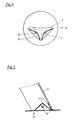
- Figur 1 eine Seitenansicht einer Wippsäge, bei der zur besseren Übersichtlichkeit die Schutzverkleidungen für das Sägeblatt nicht dargestellt ist,
- Figur 2 eine Ansicht der gegenüberliegenden Seite der Wippsäge mit einem eingelegten dicken Balken,
- Figur 3 eine Ansicht gemäß Pfeil A von Figur 1, ohne Darstellung der Wippe,
- Figur 4 eine Draufsicht auf den Stanzschnitt einer Fußplatte,
- Figur 5 eine geschnittene Seitenansicht einer Fußplatte gemäß Figur 4, die an einem Stützbein angeschraubt ist,
- Figur 6 eine perspektivische Ansicht der Wippe mit einer Aufnahmewanne,
- Figur 7 einen Querschnitt durch einen Schutzkasten für das Sägeblatt,
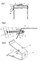
- Figur 8 eine Seitenansicht einer Sicherheitsvorrichtung, teilweise im Schnitt, unter Weglassen der für die Konstruktion unwichtigen Teile und
- Figur 9 eine perspektivische Ansicht einer Klemmfeder.
- Figur 1 zeigt eine Seitenansicht einer Wippsäge, bei der zur besseren Übersichtlichkeit die Schutzverkleidungen für das Sägeblatt 22 nicht dargestellt sind. Ein Motor 1 treibt über seinen Wellenstummel direkt ein rundes Sägeblatt 22 an. Vorzugsweise kommt ein Elektromotor für 220 Volt Wechselstrom zur Anwendung. Der Motor 1 ist auf einer haubenartigen Motorkonsole 2 festgeschraubt, die aus einer verzinkten Blechplatte mit allseits nach unten gebogenen Rändern besteht. Der mittlere, waagerechte Teil der Blechplatte bildet den Konsolenboden 3 und die umgebogenen Ränder die Konsolenwände 4, 4a, die mit ihren seitlichen Kanten 39 nur lose aneinanderstoßen und nicht direkt, z. B. durch eine Schweißnaht, miteinander verbunden sind. Wie in Figur 3 gezeigt, wird die Konsolenwand 4a, an der der Schutzkasten 23 für das Sägeblatt 22 plan anliegt, vom Konsolenboden 3 aus senkrecht nach unten gebogen. Die übrigen Konsolenwände 4 schließen, wie in Figur 8 dargestellt, mit dem Konsolenboden 3, einen Winkel von vorzugsweise mehr als 90° ein.
- Die Motorkonsole 2 ruht aus Stützbeinen 5 aus verzinktem Stahlblech, mit dem sie verschraubt ist. Die Stützbeine 5 sind im Querschnittprofil L-förmig und besitzen eine in Längsrichtung sich von oben nach unten keilförmig verjüngende Kontur. Vorzugsweise haben die Stützbeine 5 auch eingeprägte, die Stabilität erhöhende Sicken.
- Figur 3 zeigt die Zuordnung der Stützbeine 5 zur Motorkonsole 2. Die beiden, dem Sägeblatt 22 benachbarten Stützbeine 5 liegen mit einem ihrer L-Schenkel flächig an der Innenseite je einer Konsolenwand 4 an und sind mit dieser verschraubt. Die Befestigungspunkte befinden sich ungefähr auf halber Länge der Konsolenwände 4. Die beiden anderen Stützbeine 5 sind auf der Innenseite der dem Sägeblatt 22 abgewandten Foken der Motorkonsole 2 angeschraubt. Der Winkel, in dem die L-Schenkel der Stützbeine 5 zueinander stehen, entspricht dem Raumwinkel, den die beiden Ecken bildenden Konsolenwände 4 miteinander einschließen. Aus diesem Grund schmiegen sich die Stützbeine 5 flächig an die Innenseiten der Konsolenwände 4. Da der Winkel zwischen dem Konsolenboden 3 und den drei Konsolenwänden 4 vorzugsweise größer als 90° ist, erstrecken sich die Stützbeine 5, die durch ihre flächige Anlage eine Verlängerung der Konsolenwände 4 bilden, schräg nach außen.
- Die Stützbeine 5 sind mit ihren Nachbarbeinen durch Streben 6 bzw. Lagerstreben 7 verbunden und verschraubt. Diese profilierten Streben 6, 7 werden ebenfalls aus verzinkten Blechen gestanzt und gebogen.
- An jedes Stützbein 5 ist eine Fußplatte 8 angepaßt und angeschraubt. Diese Fußplatte 8 ist ebenfalls ein Stanz- und Biegeteil aus verzinktem Blech.
- Figur 4 zeigt den Stanzschnitt für eine Fußplatte 8. Die Fußplatte 8 weist einen T-förmigen Trennschnitt 9 und zwei oder auch mehr Augen 10 auf. Der T-Schnitt 9 formt in Verbindung mit den beiden gestrichelten Biegelinien 12 zwei dreieckige Lappen 11, die nach dem Stanzen entlang der Biegelinien 12 schräg nach oben gebogen werden. Der Winkel zwischen den Lappen 11 und der waagerechten Fußplatte 8 ist gleich groß wie der Winkel, den das schräg nach außen verlaufende Stützbein 5 mit der Horizontalen einschließt.
- Figur 5 verdeutlicht, daß das an seinem unteren Ende entsprechend schräg abgeschnittene Stützbein 5 flächig auf der Bodenplatte 8 aufsteht und daß durch die gleichen Winkel die Lappen 11 sich plan an die Innenseiten der Schenkel des Stützbeines 5 anlegen. Beim Biegen bleibt die runde Form der Augen 10 erhalten, so daß die Lappen 11 darüber exakt mit den Schenkeln der Stützbeine 5 verschraubt werden können. Durch diese Konstruktion werden die Verbindungsschrauben nur auf Zug und nicht auf Schub beansprucht, da die schuberzeugenden Auflagekräfte direkt von der Platte 8 auf die Stützbeine 5 geleitet werden und nur die zug- oder druckerzeugenden Seitenführungskräfte von den Lappen 11 über die Verbindungsschrauben auf die Schenkel der Stützbeine 5 geleitet werden.
- Wie aus Figur 3 zu entnehmen, wird der Schutzkasten 23 mit der Motorkonsole 2 und einer Lagerstrebe 7 verschraubt.
- Der Schutzkasten 23 weist an seinen beiden Seitenwänden ausgestanzte und herausgebogene Klemmnasen 25 auf. Der Schutzkastendeckel 24 ist etwas breiter als der Schutzkasten 23, so daß man ihn über den Schutzkasten 23 schieben kann. Dabei greifen die Ränder der Seitenwände des Schutzkastendeckels 24 in den Zwischenraum zwischen den Klemmnasen 25 und den Seitenwänden des Schutzkastens 23.
- In Figur 7 ist diese Eingriffsstellung im Querschnitt dargestellt. Mittels Schrauben und Flügelmuttern 26 wird der Schutzkastendeckel 24 gegen die Klemmnasen 25 des Schutzkastens 23 gepreßt. Da die Klemmnasen 25 auf Druck elastisch etwas nachgeben, stützt sich der Schutzkastendeckel 24 gleichzeitig an allen Nasen ab. Diese Verbindung wird durch die vorhin genannten Schrauben vorgespannt und kann dadurch auch bei starken Schwingungen keine Klappergerdusche erzeugen. Der Zwischenraum zwischen den Klemmnasen 25 und den Seitenwänden des Schutzkastens 23 ist so eng bemessen, daß die Seitenwände des Schutzkastendeckels darin eingeklemmt werden und somit auch zur Seite keine Bewegungsfreiheit haben.
- Wie aus den Figuren 1 und 2 ersichtlich, ist die Zuführvorrichtung für das Sägegut in Form einer Wippe 13 ausgebildet, die an den beiden Lagerstreben 7 schwenkbar angelenkt ist.
- Figur 6 zeigt eine perspektivische Ansicht der Wippe 13, die aus zwei, zum Sägeblatt 22 hin offenen U-Profilen 14, 15 besteht, die an ihren oberen Enden durch den breiten Teil 16a eines Rückhaltebleches 16 miteinander verbunden sind. Auf der anderen Seite des U-Profils 15 ist fluchtend zum breiten Teil 16a ein schmaler Teil 16b des Rückhaltebleches 16 befestigt. Zwischen den beiden U-Profilen 14, 15 ist auch der breite Teil 18a des Sägetisches 18 befestigt, der ebenfalls auf der anderen Seite des U-Profils 15 einen schmalen Teil 18b aufweist. Zwischen den beiden Teilen 18a und 18b des Sägetisches 18 entsteht damit ein Spalt 17 von der Breite des U-Profiles 15. Beim Zuführen des Sägeguts wird die Wippe 13 geschwenkt und das Sägeblatt 22 passiert diesen Spalt 17. Beidseits des Spaltes 17_ sind am breiten Teil 18a und am schmalen Teil 18b des Sägetisches 18 Abdeckschürzen 20 angebracht. Die Abdeckschürzen 20 und das zum Sägeblatt 22 hin offene U-Profil 15 bilden somit einen Schacht, durch den die Sägespäne nach unten abgeführt werden. Das U-Profil 15 fungiert beim Sägen auch als wippenseitige Sägeblattabdeckung.
- Der Sägetisch 18 bildet zusammen mit dem Rückhalteblech 16 eine Wanne 21 zur Aufnahme des Sägegutes. Diese Wanne 21 weist, wie in Figur 1 dargestellt, eine besondere Form auf. Sie entspricht im Querschnitt etwa einem U, wobei der dem Sägeblatt 22 nächstliegende Schenkel des U im oberen Teil zum Sägeblatt 22 abgewinkelt ist. Den Steg und den gekröpften Schenkel des U bildet dabei vorzugsweise der Sägetisch 18. Diese Form der Aufnahmewanne 21 hat den Vorteil, daß wie in Figur 1 gezeigt, Balken oder Stangen bis zu einem Durchmesser von ca. 15 cm im unteren Teil der U-förmigen Aufnahmewanne 21 lagern und in einem Schnitt durchgesägt werden können. Andererseits wird durch die gekröpfte U-Form die Öffnungsweite der Aufnahmewanne 21 so vergrößert, daß auch sehr dicke Balken relativ tief in der Aufnahmewanne 21 zu liegen kommen. Durch die tiefe Lage in der Aufnahmewanne 21 reicht auch bei dicken Balken der Schnitt des Sägeblattes 22 bis über die Mittellinie des Balkens. Will man keine so dicke Balken sägen, kann man wegen der vorteilhaften Form der Aufnahmewanne 21 stattdessen den Durchmesser des Sägeblattes 22 verkleinern. Die Verkleinerung des Sägeblattes 22 erlaubt die Verwendung eines relativ leistungsschwachen Elektromotors, der an 220 Volt Wechselstrom angeschlossen werden kann.
- Am oberen Teil der Wippe 13 ist ein Handgriff 19 befestigt. Fast alle Teile der Wippe 13 sind Stanz- und Biegeteile aus verzinktem Blech, die ausschließlich durch Schrauben miteinander verbunden werden.
- Wie schon erwähnt, wird beim Zuführen das Sägegut zum ortsfest gelagerten, rotierenden Sägeblatt 22 geschwenkt. Um auch dicke Balken sägen zu können und gleichzeitig das Rotieren des Sägeblattes 22 nach oben hin abzudecken, ist gem. Fig. 2 ein oberer Blattschutz 27 vorgesehen, der an seiner Vorderseite ein vorzugsweise gebogenes Gleitblech 28 aufweist und der an seiner Rückseite am Schutzkasten 23 schwenkbar befestigt ist. Wird auf der Wippe 13 ein dicker Balken zugeführt, drückt dieser das Gleitblech 28 und damit den oberen Blattschutz 27 nach oben weg. Dies geschieht gegen die Kraft einer nicht dargestellten Feder, die den oberen Blattschutz 27 selbsttätig in seine Ruheposition zurückholt.
- In Figur 1 ist eine Sicherheitsvorrichtung 29 angedeutet, die die Wippe 13 aus jeder Zuführstellung in die Ausgangs- oder Ruheposition zurückschwenkt. In Fig. 8 und 9 ist die Sicherheits- 'vorrichtung 29 im einzelnen schematisch dargestellt. Sie besteht aus einer Steuerstange 30, die an der Wippe 13 schwenkbar befestigt ist. Auf der Steuerstange 30 ist eine Druckfeder 32 geführt, die sich einerseits an einer Scheibe 31 und andererseits an einem Bügel 35 in Form einer Klemmfeder abstützt, die in der Konsolenwand 4 ortsfest gelagert ist. Die Steuerstange 30 passiert die Klemmfeder 35 durch eine Bohrung 38 (vgl. Fig. 9) und weist dahinter noch eine große Scheibe 33 und eine Mutter 34 auf. Bei einer Schwenkbewegung der Wippe 13 wird die Steuerstange 30 durch die Öffnung 38 in der Klemmfeder 35 geschoben, wodurch die Druckfeder 32 gespannt wird und rückstellende Federkräfte entwickelt.
- Ohne Sicherheitsvorrichtung 29 würde die Wippe 13 in ihrer Ruhestellung durch ihr Eigengewicht nach unten kippen. Das wird durch die Steuerstange 30 verhindert, die sich über die aufgeschraubte Mutter 34 und die Scheibe 33 an der Klemmfeder 35 abstützt, die wiederum normalerweise unverrückbar in der Konsolenwand 4 steckt.
- Figur 9 zeigt eine perspektivische Ansicht dieser Klemmfeder 35. Es handelt sich dabei um ein gestanztes, gebogenes und verzinktes Blechteil in der Art eines U-förmigen Bügels. Auf den beiden Schenkeln der Klemmfeder 35 sind in unterschiedlicher Entfernung vom Quersteg Taillierungen 36 angebracht, die zur Befestigung der Klemmfeder in der Konsolenwand 4 dienen. Der Steg der U-förmigen Klemmfeder 35 ist noch mit einer Bohrung 38 versehen, durch die die Steuerstange 30 ragt. Figur 3 zeigt in der zum Betrachter weisenden Konsolenwand 4 eine Öffnung 37. In diese kreuzförmige Öffnung 37 wird die Klemmfeder 35 gesteckt. Die normale Bügelbreite der Klemmfeder 35 entspricht der maximalen Breite der kreuzförmigen Öffnung 37, wohingegen die Bügelbreite der Klemmfeder 35 in Höhe der Taillierungen 36 der Breite der senkrechten Schenkel der kreuzförmigen Öffnung 37 entspricht. Die Öffnungsweite der Klemmfeder 35, gemessen zwischen den beiden Taillierungen 36, ist größer als die Höhe der senkrechten Kreuzschenkel der Öffnung 37. Zum Einsetzen der Klemmfeder in die Öffnung 37 muß die U-förmige Klemmfeder 35 an ihren freien Enden zusammengedrückt werden. Beim Loslassen der freien Enden spreizt sich die Klemmfeder 35 wieder auf. Befinden sich nun die Taillierungen 36 genau in Höhe der Konsolenwand 4, drückt sich die Federklemme 35 mit diesen schmalen Taillierungen 36 in die schmalen senkrechten Stege der kreuzförmigen Öffnung 37. Die Dicke der Taillierungen 36 entspricht dabei der Wandstärke der Konsolenwand 4. In dieser sog. Raststellung ist die Klemmfeder 35 unverrückbar in der Öffnung 37 festgeklemmt, da sie vor und hinter der Taillierung 36 ihre volle Bügelbreite wieder aufweist und an diesen Stellen an der Innen- und Außenseite der Konsolenwand 4 anliegt. Die Konsolenwand 4 greift also wie eine Verzahnung in die Taillierungen 36 der Klemmfeder 35.
- Beim Schwenken der Wippe 13 bewegen sich die angeschlossene Steuerstange 30 hauptsächlich in horizontaler Richtung, weshalb auch die Klemmfeder 35 waagerecht in die Motorkonsole 2 gesteckt werden muß. Da jedoch die Konsolenwand 4 schräg nach unten verläuft (vgl. Figur 8), müssen die Taillierungen 36, wenn die Klemmfeder 35 horizontal in die Konsolenwand 4 gesteckt werden soll, gegeneinander versetzt sein, wie das aus Figur 9 ersichtlich ist.
- Der Schwenkweg der Wippe 13 nach rückwärts ist, wie schon erwähnt, beschränkt. Zum Wechseln des Sägeblattes 22 müssen jedoch die an den Teilen 18a und 18b des Sägetisches 18 befestigten Abdeckschürzen 20 (vgl. Figur 2) wenigstens teilweise entfernt werden. Zu diesem Zweck muß man die Wippe 13 über ihre Ruhestellung hinaus nach rückwärts verschwenken. Durch Zusammendrücken der freien Enden der Klemmfeder 35 geraten die Taillierungen 36 außer Eingriff mit den senkrechten Schenkeln der Öffnung 37, so daß nun die Klemmfeder 35 und mit ihr die Steuerstange 30 aus der Motorkonsole 2 herausgezogen werden können. Der Auszug wird jedoch durch die Scheibe 33 beschränkt, die so groß ist, daß sie die Öffnung 37 in der Konsolenwand 4 nicht passieren kann. Kommt sie zur Anlage an die Konsolenwand 4, hält sie über die Mutter 34 die Steuerstange 30 zurück. Schwenkt man die Wippe 30 wieder vorwärts in Richtung Sägeblatt 22 schiebt die Druckfeder 32 die Klemmfeder 35 in deren Raststellung in der Motorkonsole 2 zurück. Dadurch kann die Sicherheitsvorrichtung 29 nicht versehentlich außer Betrieb gesetzt werden.

Claims (8)
Priority Applications (1)
| Application Number | Priority Date | Filing Date | Title |
|---|---|---|---|
| AT82106883T ATE18733T1 (de) | 1981-08-07 | 1982-07-30 | Spanabhebende heimwerkermaschine, insbesondere wippsaege. |
Applications Claiming Priority (2)
| Application Number | Priority Date | Filing Date | Title |
|---|---|---|---|
| DE8123262U | 1981-08-07 | ||
| DE19818123262U DE8123262U1 (de) | 1981-08-07 | 1981-08-07 | Spanabhebende heimwerkermaschien, insbesondere wippsaege |
Publications (3)
| Publication Number | Publication Date |
|---|---|
| EP0071902A2 EP0071902A2 (de) | 1983-02-16 |
| EP0071902A3 EP0071902A3 (en) | 1983-07-20 |
| EP0071902B1 true EP0071902B1 (de) | 1986-03-26 |
Family
ID=6730210
Family Applications (1)
| Application Number | Title | Priority Date | Filing Date |
|---|---|---|---|
| EP82106883A Expired EP0071902B1 (de) | 1981-08-07 | 1982-07-30 | Spanabhebende Heimwerkermaschine, insbesondere Wippsäge |
Country Status (3)
| Country | Link |
|---|---|
| EP (1) | EP0071902B1 (de) |
| AT (1) | ATE18733T1 (de) |
| DE (2) | DE8123262U1 (de) |
Families Citing this family (8)
| Publication number | Priority date | Publication date | Assignee | Title |
|---|---|---|---|---|
| AT400938B (de) * | 1994-11-28 | 1996-04-25 | Putz Stefan | Brennholzkreissäge |
| DE202006010777U1 (de) * | 2006-07-11 | 2006-09-28 | Scheppach Fabrikation Von Holzbearbeitungsmaschinen Gmbh | Brennholzkreissäge |
| CN102528469A (zh) * | 2012-03-02 | 2012-07-04 | 青岛地恩地机电科技股份有限公司 | 机床支架 |
| EP3693143B1 (de) * | 2019-02-08 | 2021-10-20 | Scheppach Fabrikation von Holzbearbeitungsmaschinen GmbH | Wippkreissäge |
| CN110587023B (zh) * | 2019-08-29 | 2024-12-10 | 安徽艾嘉门窗有限公司 | 一种用于45度角自动切割单支门窗铝塑型材的加工中心 |
| CN111250783B (zh) * | 2020-03-26 | 2025-03-07 | 南方电网电力科技股份有限公司 | 一种电锯和适用于机器人的电锯设备 |
| CN114789341B (zh) * | 2022-03-09 | 2023-05-02 | 无锡威卡威汽车零部件有限公司 | 一种用于侧梁的双头锯铣机器人 |
| CN119839539B (zh) * | 2025-03-21 | 2025-05-27 | 四川筑盾人防工程设备有限公司 | 一种临时支墩制作焊接设备 |
Family Cites Families (7)
| Publication number | Priority date | Publication date | Assignee | Title |
|---|---|---|---|---|
| FR965169A (de) * | 1950-09-05 | |||
| DE494472C (de) * | 1929-01-13 | 1930-03-24 | Mathias De Zurik | Verfahren und Vorrichtung zum Entfernen unerwuenschter Teile, wie eingewachsene AEste, Rinde u. dgl., aus einem Holzkoerper, der zur Herstellung von Holzschliff dienen soll |
| FR989220A (fr) * | 1944-02-16 | 1951-09-06 | Carter de protection à mâchoires ouvrantes pour outil, notamment pour une scie rotative | |
| US3081841A (en) * | 1962-04-03 | 1963-03-19 | Thomas J Mauro | Sheet metal legs |
| DE1453033A1 (de) * | 1963-06-20 | 1969-01-02 | Lutz Kg | Kreissaege |
| DE2011033A1 (de) * | 1970-03-09 | 1971-09-23 | Hempelmann W | Verstrebung fur Standbeine \on Maschinen, insbesondere Tischkreissagen |
| USRE30689E (en) * | 1976-09-14 | 1981-07-28 | Foldable bench for a portable hand-held circular saw |
-
1981
- 1981-08-07 DE DE19818123262U patent/DE8123262U1/de not_active Expired
-
1982
- 1982-07-30 DE DE8282106883T patent/DE3270104D1/de not_active Expired
- 1982-07-30 EP EP82106883A patent/EP0071902B1/de not_active Expired
- 1982-07-30 AT AT82106883T patent/ATE18733T1/de not_active IP Right Cessation
Also Published As
| Publication number | Publication date |
|---|---|
| EP0071902A3 (en) | 1983-07-20 |
| DE3270104D1 (en) | 1986-04-30 |
| DE8123262U1 (de) | 1982-02-18 |
| EP0071902A2 (de) | 1983-02-16 |
| ATE18733T1 (de) | 1986-04-15 |
Similar Documents
| Publication | Publication Date | Title |
|---|---|---|
| EP2171173B1 (de) | Glasscheiben-geländer | |
| EP0243612B1 (de) | Vorrichtung zur Verankerung von Platten | |
| EP1442942A1 (de) | Flanschverbindung zwischen einem Fahrzeuglängsträger und einem daran ansetzbaren Trägerelement | |
| DE3530694A1 (de) | Vorrichtung zur verankerung von platten | |
| EP1075350A1 (de) | Führungswagen für ein von hand führbares arbeitsgerät, insbesondere für einen trennschleifer | |
| EP0071902A2 (de) | Spanabhebende Heimwerkermaschine, insbesondere Wippsäge | |
| DE102012000402B3 (de) | Konsole zur Halterung eines Tanks | |
| DE9307229U1 (de) | Schutzzaun zur Absicherung von Gefahrzonen | |
| DE4313330C2 (de) | Verklammerungsorgan | |
| EP0649951B1 (de) | Betonschalung | |
| DE29717355U1 (de) | Bausatz zum modulartigen Aufbau einer aus drei Hauptmodulen aufgebauten Konsole | |
| DE60102312T2 (de) | Kraftfahrzeug- Lenksäulenbefestigungssystem | |
| EP1811233B1 (de) | Wandbefestigungssystem mit Abstandshalter für mit Aufhängelaschen versehene plattenförmige Gegenstände wie Heizkörper | |
| DE202018104969U1 (de) | Ablagevorrichtung für Bad- oder Duschutensilien | |
| DE202008015077U1 (de) | Adapter zur Befestigung von Solarmodulen, mit Adapter befestigte Solarmodule und Werkzeug zum Lösen der Befestigung | |
| EP1384421B1 (de) | Sockelblende | |
| EP4263977A1 (de) | Rahmengestell mit einem mastbock zur lagerung eines dickstoffverteilermasts | |
| DE3308473C2 (de) | Balken- oder Rippendecke | |
| DE10006761C2 (de) | Sägebock zum Ablängen von Langholz | |
| DE29513842U1 (de) | Tischkreissäge | |
| EP0627338A1 (de) | Einheitsteil-Sitz | |
| DE9302065U1 (de) | Befestigung für Gliederheizkörper | |
| EP0516999A1 (de) | Aus Leichtmetall bestehender Seitenholm für eine Treppe | |
| EP2345086A2 (de) | Adapter zur befestigung von solarmodulen, mit adaptern befestigte solarmodule und verfahren zur befestigung von solarmodulen | |
| EP0117505A2 (de) | Holzbearbeitungsmaschine |
Legal Events
| Date | Code | Title | Description |
|---|---|---|---|
| PUAI | Public reference made under article 153(3) epc to a published international application that has entered the european phase |
Free format text: ORIGINAL CODE: 0009012 |
|
| AK | Designated contracting states |
Designated state(s): AT BE CH DE FR GB IT LI |
|
| PUAL | Search report despatched |
Free format text: ORIGINAL CODE: 0009013 |
|
| AK | Designated contracting states |
Designated state(s): AT BE CH DE FR GB IT LI |
|
| 17P | Request for examination filed |
Effective date: 19831224 |
|
| ITF | It: translation for a ep patent filed | ||
| GRAA | (expected) grant |
Free format text: ORIGINAL CODE: 0009210 |
|
| AK | Designated contracting states |
Kind code of ref document: B1 Designated state(s): AT BE CH DE FR GB IT LI |
|
| PG25 | Lapsed in a contracting state [announced via postgrant information from national office to epo] |
Ref country code: BE Effective date: 19860326 |
|
| REF | Corresponds to: |
Ref document number: 18733 Country of ref document: AT Date of ref document: 19860415 Kind code of ref document: T |
|
| REF | Corresponds to: |
Ref document number: 3270104 Country of ref document: DE Date of ref document: 19860430 |
|
| ET | Fr: translation filed | ||
| PG25 | Lapsed in a contracting state [announced via postgrant information from national office to epo] |
Ref country code: AT Effective date: 19860730 |
|
| PG25 | Lapsed in a contracting state [announced via postgrant information from national office to epo] |
Ref country code: LI Effective date: 19860731 Ref country code: CH Effective date: 19860731 |
|
| PLBE | No opposition filed within time limit |
Free format text: ORIGINAL CODE: 0009261 |
|
| STAA | Information on the status of an ep patent application or granted ep patent |
Free format text: STATUS: NO OPPOSITION FILED WITHIN TIME LIMIT |
|
| 26N | No opposition filed | ||
| REG | Reference to a national code |
Ref country code: CH Ref legal event code: PL |
|
| PGFP | Annual fee paid to national office [announced via postgrant information from national office to epo] |
Ref country code: FR Payment date: 19910513 Year of fee payment: 10 |
|
| PGFP | Annual fee paid to national office [announced via postgrant information from national office to epo] |
Ref country code: DE Payment date: 19910516 Year of fee payment: 10 |
|
| PGFP | Annual fee paid to national office [announced via postgrant information from national office to epo] |
Ref country code: GB Payment date: 19910719 Year of fee payment: 10 |
|
| ITTA | It: last paid annual fee | ||
| PG25 | Lapsed in a contracting state [announced via postgrant information from national office to epo] |
Ref country code: GB Effective date: 19920730 |
|
| GBPC | Gb: european patent ceased through non-payment of renewal fee |
Effective date: 19920730 |
|
| PG25 | Lapsed in a contracting state [announced via postgrant information from national office to epo] |
Ref country code: FR Effective date: 19930331 |
|
| PG25 | Lapsed in a contracting state [announced via postgrant information from national office to epo] |
Ref country code: DE Effective date: 19930401 |
|
| REG | Reference to a national code |
Ref country code: FR Ref legal event code: ST |