EP0071913A2 - Système de support pour surfaces de travail - Google Patents
Système de support pour surfaces de travail Download PDFInfo
- Publication number
- EP0071913A2 EP0071913A2 EP82106919A EP82106919A EP0071913A2 EP 0071913 A2 EP0071913 A2 EP 0071913A2 EP 82106919 A EP82106919 A EP 82106919A EP 82106919 A EP82106919 A EP 82106919A EP 0071913 A2 EP0071913 A2 EP 0071913A2
- Authority
- EP
- European Patent Office
- Prior art keywords
- leg
- bracket
- mounting
- support
- tables
- Prior art date
- Legal status (The legal status is an assumption and is not a legal conclusion. Google has not performed a legal analysis and makes no representation as to the accuracy of the status listed.)
- Withdrawn
Links
- 238000003860 storage Methods 0.000 claims abstract description 27
- 230000013011 mating Effects 0.000 claims description 5
- 238000010276 construction Methods 0.000 claims description 4
- 238000005096 rolling process Methods 0.000 claims 1
- 230000000712 assembly Effects 0.000 description 8
- 238000000429 assembly Methods 0.000 description 8
- 238000009434 installation Methods 0.000 description 2
- 238000004519 manufacturing process Methods 0.000 description 2
- 230000004048 modification Effects 0.000 description 2
- 238000012986 modification Methods 0.000 description 2
- 230000006978 adaptation Effects 0.000 description 1
- AZDRQVAHHNSJOQ-UHFFFAOYSA-N alumane Chemical group [AlH3] AZDRQVAHHNSJOQ-UHFFFAOYSA-N 0.000 description 1
- 230000008859 change Effects 0.000 description 1
- 230000000295 complement effect Effects 0.000 description 1
- 230000003247 decreasing effect Effects 0.000 description 1
- 238000004512 die casting Methods 0.000 description 1
- 230000005611 electricity Effects 0.000 description 1
- 238000005516 engineering process Methods 0.000 description 1
- 238000003754 machining Methods 0.000 description 1
- 230000007246 mechanism Effects 0.000 description 1
- 238000000034 method Methods 0.000 description 1
- 230000004044 response Effects 0.000 description 1
- 238000003892 spreading Methods 0.000 description 1
- 230000007480 spreading Effects 0.000 description 1
- 239000000126 substance Substances 0.000 description 1
- XLYOFNOQVPJJNP-UHFFFAOYSA-N water Substances O XLYOFNOQVPJJNP-UHFFFAOYSA-N 0.000 description 1
Images



Classifications
-
- A—HUMAN NECESSITIES
- A47—FURNITURE; DOMESTIC ARTICLES OR APPLIANCES; COFFEE MILLS; SPICE MILLS; SUCTION CLEANERS IN GENERAL
- A47B—TABLES; DESKS; OFFICE FURNITURE; CABINETS; DRAWERS; GENERAL DETAILS OF FURNITURE
- A47B83/00—Combinations comprising two or more pieces of furniture of different kinds
- A47B83/001—Office desks or work-stations combined with other pieces of furniture, e.g. work space management systems
-
- B—PERFORMING OPERATIONS; TRANSPORTING
- B01—PHYSICAL OR CHEMICAL PROCESSES OR APPARATUS IN GENERAL
- B01L—CHEMICAL OR PHYSICAL LABORATORY APPARATUS FOR GENERAL USE
- B01L9/00—Supporting devices; Holding devices
- B01L9/02—Laboratory benches or tables; Fittings therefor
-
- A—HUMAN NECESSITIES
- A47—FURNITURE; DOMESTIC ARTICLES OR APPLIANCES; COFFEE MILLS; SPICE MILLS; SUCTION CLEANERS IN GENERAL
- A47B—TABLES; DESKS; OFFICE FURNITURE; CABINETS; DRAWERS; GENERAL DETAILS OF FURNITURE
- A47B2200/00—General construction of tables or desks
- A47B2200/0011—Underframes
- A47B2200/002—Legs
- A47B2200/0026—Desks with C-shaped leg
-
- A—HUMAN NECESSITIES
- A47—FURNITURE; DOMESTIC ARTICLES OR APPLIANCES; COFFEE MILLS; SPICE MILLS; SUCTION CLEANERS IN GENERAL
- A47B—TABLES; DESKS; OFFICE FURNITURE; CABINETS; DRAWERS; GENERAL DETAILS OF FURNITURE
- A47B2200/00—General construction of tables or desks
- A47B2200/0011—Underframes
- A47B2200/002—Legs
- A47B2200/0027—Desks with I-shaped leg
Definitions
- the invention relates to a laboratory system including work surfaces and carts constructed from a plurality of common components.
- a modular laboratory furniture system comprises freestanding tubular frame modules and tables all of which are selectively arranged about a room.
- the system further includes mobile carts movable about the room.
- the frame modules and tables mount a horizontal work surface. Each work surface is supported on the frame modules and tables by pairs of spaced apart common support means.
- the carts also include the common support means.
- Each support means includes a hollow vertical leg of rectangular configuration and a bracket member having an extension arm for mounting to an underside of the work surface or for providing a bottom support and a base portion for mounting to the vertical leg.
- the bracket member and one portion of the leg are mounted together so that the base portion of the bracket member mates with the cross-sectional configuration of the leg.
- means are provided for mounting the work surfaces to the extension arms of certain of the bracket members.
- Supported on the frame modules, tables and carts are a variety of storage components. At least one of the storage components is mounted to rails which are detachably secured to a pair of vertical legs of a pair of the spaced-apart support means.
- the common support means for the work surfaces, tables and carts allows for the construction of tables, carts and hanging surfaces using a minimum of parts and allows for versatility in the system.
- the bracket member is a unitary, die-cast member having parallel, spaced-apart side walls joined by perpendicular webs integrally formed with the side walls.
- the leg and base portion of the bracket arm have a width preferably between 1/4 and 1/3 of the length of the extension arm.
- the wide base adds to the rigidity of the arm and provides a good load capacity.
- the vertical leg is secured to the bracket member by threaded rods which extend internally through the two parts.
- the rail secured between the vertical legs is a hollow extruded member which includes a lip for mating with an attachment member on the storage components.
- the frame modules include hanger means for releasably supporting the support means. Hanger clips are secured to the bracket members so as to mount the support means and attached work surfaces to the frame modules.
- the angular orientation of the work surfaces can be adjusted by use of a levelling means.
- the levelling means includes means mounting the top portion of the support means to a vertical support and means for pivoting the support means and attached work surface about a horizontal axis so as to level the work surface.
- the pivoting means includes a block member secured stationary relative to the support means and a rod threadedly received in the support means and having an end which bears against the block. As the rod is rotated, the support means is angularly displaced relative to the block member so as to pivot the work surface about the horizontal axis.
- Tables constructed in accordance with the invention are provided with base means for supporting the table on the floor.
- the base means comprises a bracket member used in an inverted position so that the extension arm is positioned adjacent the floor.
- the carts are constructed so that the bracket members are mounted to the bottom of the vertical leg.
- the top of the leg mounts a cap member and the cap member is secured to the leg by the same fastener which secures the bracket member and leg together.
- the cart includes casters which allow the cart to be rolled about the room.
- the above-described common components allow for the construction and modification of a laboratory system in a simple manner.
- the common components are detachably secured together and are readily interchangeable so as to accomodate changes in the needs of the laboratory. Further, the components have a uniform configuration and provide a pleasing aesthetic appearance.
- a laboratory system in accordance with the invention is shown as installed in a room 10.
- the laboratory system allows for great efficiency by providing flexibility in the arrangement of work stations in order to meet a specific need.
- the laboratory system includes various work surfaces, storage components, transportation carts, utility chases and seating, all of which are arranged in a selected configuration.
- the system is constructed of a number of common components used in the various carts, work surfaces and the like.
- the system allows for adaptation to changing requirements in the laboratory and the evolution of new parts, all of which can interface with the existing components. Further, the components are detachably secured together which allows for easy assembly and disassembly of the parts.
- the lab system is installed in a room 10 having a floor 12, ceiling 14 and walls 16. Disposed in the ceiling are utility and service lines 18 necessary for telephone, electricity, water, gas and the like.
- the utility and service lines can be disposed in the floor or wall in addition to or instead of the ceiling.
- the work stations 20 are selectiveively arranged about the room.
- the configurations of the work stations 20 are selected to meet the particular needs of a laboratory.
- the work stations 20 comprise frame modules 22 which are tubular, three-dimensional rigid structures which support work surfaces, storage components and the like to be described below.
- the frame modules 22 are all freestanding and can be arranged in the middle of a room or adjacent a wall 16.
- the frame modules 22 include hanging intelligence for supporting the work surfaces, storage components and the like.
- the storage components include lockers 26, such as that shown in U. S. Patent No. 3,712,697 issued January 23, 1973, flipper cabinets 28 which are hung on the frame modules 22 above the work surface, drawers 30 mounted beneath the work surface and shelving 32 mounted to the frame module 22.
- the type and number of storage components is selected to meet the needs of the laboratory and all of the components are arranged so as not to interfere with the work areas in the laboratory.
- the work surfaces can be in the form of hanging surfaces 34 which are mounted to the frame modules 22 or a wall 16 in a manner to be described below and freestanding tables 36 which can be arranged adjacent a frame module 22, adjacent a wall 16 of the room, or placed in the room independently of a vertical support.
- Both the hanging surfaces 34 and freestanding tables 36 include support assemblies 38 which comprise one of the common elements of the system and mount the work surfaces. The configuration of the support assemblies 38 will be described in more detail with reference to Figures 2, 9 and 10.
- carts 40 and transportation devices 42 can also be used to carry equipment and supplies through the laboratory system.
- the carts 40 can be used as a transportation mechanism and are constructed with the components used to construct the hanging surfaces 34 and tables 36.
- Transporters 42 are used to carry the lockers 26 throughout the laboratory area.
- a number of seats are arranged in the room.
- a vertical utility chase 46 provided on at least one frame module 22 extends to the ceiling 14 to allow for the connection of the utilities and service lines 18 contained in the ceiling 14 of the room to the work stations 20.
- the frame modules serve as horizontal chases for connecting the utilities to the different work areas.
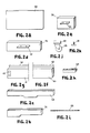
- Figures 2a through 2k illustrate the common components which are used to construct the hanging surfaces 34, tables 36 and carts 40 of the above-described laboratory system.
- the components provide a means for assembling the various work surfaces, carts and the like which are described above and provide a simple method of building a system with a minimum of parts. By using such common parts, tooling requirements are held to a minimum.
- the parts are secured together in a releasable fashion which enhances the interchangeability and versatility of the components used in the system.
- Figure 2a illustrates a work surface 50 used in constructing a hanging surface 34 or a freestanding table 36 as shown in Figure 1.
- the work surface 50 is mounted to the frame modules 22 or constructed into a freestanding table 36 by using support assembly 38.
- the work surface 50 can have a variety of sizes depending upon the particular application. Various sizes and configurations of the surfaces 50 are shown in Figure 1.
- the work surfaces 50 can be provided in a range of performance levels each having differing load capacities and resistances to chemicals, heat and the like. In this way, the work surface 50 can be selected to meet the specific needs of the laboratory.
- the surfaces 50 are mounted to either the frame modules 22 or constructed into a freestanding table 36 using support arms 52 or 54 (see Figures 2b and 2c).
- the support arms 52, 54 are integral, die cast parts.
- the support arms 52 and 54 will be described below in greater detail with reference to Figure 9. Die casting of the parts allows for relatively easy manufacture and requires a minimum of finishing or machining.
- the support arms 52 and 54 are adapted to be mounted beneath the work surface 50 and to the frame modules 22 or walls 16.
- Support arm 52 is a single width support arm used to suspend a work surface 50 from the frame modules 22 or walls 16.
- the support arms 52 can also be used to construct a freestanding table 36 by using the support arms 52 as a base for the table.
- the support arm 52 can also be used to construct carts 40, with the arm 52 serving as a base for the cart.
- the double width arm 54 can be used to construct larger freestanding tables 36 with the arm 54 functioning both as a support for the work surface 50 and as a base for the table 36.
- the support arms 52 and 54 are connected to leg tubes 56 and 58 (see Figures 2d and 2e) which also make up part of the support assembly 38 which forms part of the cart 40, freestanding table 36, and hanging work surface 34.
- the leg tubes 56, 58 are generally hollow extruded aluminum parts having a rectangular cross-section.
- the leg tubes 56, 58 preferably come in two standard lengths, an elongate tube 56 and a shorter tube 58.
- the elongate tube 56 is used in constructing freestanding tables 36 and carts 40 with the tubes 56 forming a portion of the leg.
- the shorter leg tube 58 is preferably used in constructing support brackets 38 for supporting hanging surfaces 34.
- the leg tubes 56, 58 can be used with either of the support brackets 52 and 54 so that the four pieces can be used interchangeably to construct a hanging surface, table or cart configuration.
- the leg tubes 56 and 58 include a fastening means for mounting stretcher rails 60, 61 (see Figures 2f and 2g) which support storage components, such as drawers 30, thereon.
- the fastening means is in the form of a rectangular bracket 57, 59 which is either welded or bolted to the leg tubes.
- the stretcher rails 60, 61 as shown in Figures 2f and 2g, is a hollow elongate tubular member having a generally rectangular cross-section.
- the stretcher rails 60, 61 are adapted to be mounted between two leg tubes of either a freestanding work surface 36, a hanging surface 34 or a cart 40 as will be described below with reference to Figure 3.
- the end portion of rail 60 used with tables 36 and carts 40 has an open cross-section ( Figure 2f) which receives the bracket 57.
- the open end of the rail 60 is slid over the bracket 57 and fastened in place by screws.
- the end of rail 61 ( Figure 2g) used with hanging surfaces 34 has a notched surface 63 which receives the bracket 59 in an overlapping manner.
- the rail 61 is secured to the bracket 59 by screws.
- the stretcher rails 60, 61 include a lip 62 which receives a mating projection on a storage component such as shown in U. S. Patent No. 3,212,646, issued October 19, 1965.
- the stretcher rails 60, 61 allow for the mounting of storage components such as drawers 30 beneath the work surface 50 or to a cart 40 without the need for hanging the storage component directly from the work surface 50 and thereby necessitating an increased load capacity for the surface 50.
- the support assembly 38 which comprises a leg tube 58 and a support arm 52, is completed by an end cap 64 (Figure 2h) mounted at the bottom portion of the leg tube 58.
- the end cap 64 is a die cast part secured to the support assembly 38 by elongate threaded tie rods 66 ( Figure 2i) which secure the end cap 64 to the support arm 52.
- the tie rods 66 pass through the leg tubes 58 but are not secured thereto.
- the end cap 64 is also used in constructing the carts 40.
- the table 36 can be provided with either casters 68 or glides 70 ( Figures 2j and 2k).
- the casters 68 or glides 70 are mounted to the base of the table which is constructed using one of the support arms 52 or 54, as will be described below.
- a pad 69 Interposed between the caster 68 and the table base is a pad 69 which mounts the caster 68 to the table base.
- FIG. 3 illustrates a freestanding table 36 constructed in accordance with the invention using the above-described common components.
- the table 36 includes a work surface 50 supported on support arms 52.
- the legs of the table 36 are in the form of elongate leg tubes 56 with the base of the table being made up of inverted support arms 52.
- the two support arms are secured together by means of the tie rods 66.
- Extending between the legs of the table are stretcher rails 60 on which can be mounted hanging storage components, such as drawers 30.
- the rail 60 is mounted in a detachable fashion by positioning the rail 60 between the leg tubes 56 and sliding the ends of the rail 60 onto the brackets 57. The screws are then fastened to secure the rail 60 in place. No special tools other than a screw driver are needed to mount the rail 60 and the rail 60 is readily detachable so as to allow for restructuring of the system.
- the table 36 can be provided either with casters 68 or glides 70 to support the table on the floor.
- Figure 4 shows a hanging surface 34 which is mounted to a vertical wall 16 or frame module 22 as in Figure 1.
- the hanging surface 34 includes a surface 50 supported on a support assembly 38 comprising arm 52, tube 58 and end caps 64 which are secured together by means of the elongate tie rod 66 as described in further detail with reference to Figure 9.
- a hanger clip 81 is screwed to the back of the support assembly 38 so that the clips 81 can be received in elongate slots 84 in stiles 82 secured to the wall 16 or frame module 22.
- a stretcher rail 61 can be supported between the leg tubes 58 of the hanging surface 34, as described above with respect to rail 60, so as to provide for mounting of hanging storage components.
- the notch in the end of rail 61 is placed adjacent bracket 59 so as to overlap the bracket 59.
- the rail 61 is then secured in placed with screws.
- the notches 63 in the ends of the rail 61 allow for the installation of the rail without dismantling the hanging surface. In this regard, the notches allow the rail 61 to be positioned without spreading the support assemblies 38 which would disturb the adjacent work surfaces.
- a second stretcher rail 61 can be mounted below the work surface 50 to provide additional storage capacity.
- the second rail is supported on leg tubes 58, in the above-described fashion, which are secured to the stiles 82 by means of clips 81.
- the clips 81 are attached to end caps 64 which are mounted to the leg tubes 58 by the threaded rods 66.
- the clips 81 are secured to the end caps 64 through screws in a manner similar to that shown in Figure 9.
- Figure 5 shows an alternate form of a hanging surface 34 wherein a hanger rail 72 is releasably secured to a wall-supported rail 76 in order to releasably mount the hanging surface 34 to a vertical wall 16.
- the work surface 50 is supported by a support assembly 38 comprising support arms 52, legs 58 and end caps 64 all connected together by means of the tie rod 66.
- a stretcher rail 61 is mounted between the tubes 58 to provide for mounting of storage components.
- the rail 72 is secured to the support assemblies 38 by means of screws 73.
- the screws 73 are threaded into the rear of the support assembly 38 in the same manner that the clips 81 are secured to the support assembly 38 which is shown in Figure 9 with the screws 73 passing through apertures in the rail 72.
- the top portion of the rail 72 includes a flange 74 which is received on a complementary flange on the wall-supported rail 76.
- the bottom of the hanger rail 72 includes a channel 78 which abuts the wall and maintains the hanging surface 34 in a horizontal orientation.
- Figure 6 shows another form of a hanging surface similar to that shown in Figure 4, the distinction lying in the use of one elongate tube 56 as opposed to two shorter tubes 58 to mount the stretcher rails 61.
- Figure 7 shows another form of a freestanding work table having a large work surface 50 supported on double-width support arms 54, leg tubes 56 and a base constructed of inverted support arms 54.
- the table 36 can be provided with gliders 68 or casters 70, as described above, to allow for movement of the table 36.
- Extending between the leg tubes 56 are stretcher rails 60 which allow the table 36 to support the various hanging storage components.
- the rails 60 are mounted in the manner described above.
- FIG 8 illustrates a cart 40 constructed of the components used to make up the hanging surfaces 34 and freestanding tables 36.
- the cart 40 includes side portions constructed of leg tubes 56 which mount inverted support arms 52 so as to form a base for the cart. It thus can be seen that the sides of the carts 40 are formed by inverted support assemblies 38.
- Elongate tie rods 66 connect the leg tubes 56 to the inverted support arms 52 as well as to end caps 64 which provide a finished appearance to the cart 40.
- a handle 86 is mounted to the rear portion of the cart between the end caps 64.
- the cart 40 is provided with casters 68 mounted to caster pads 69 which allow the cart to be moved about the room.
- Mounted between the leg tubes 56 are two stretcher rails 60. The stretcher rails, which are secured in the manner described above with reference to Figure 3, allows the cart 40 to hold storage units for movement about the laboratory or provide a temporary storage device.
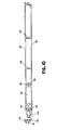
- FIGS. 9 and 10 show in detail the support assembly 38.
- the hanging surface 34 includes a work surface 50 mounted to the support assemblies 38 comprising support arms 52, leg tubes 58 and end caps 64, all of which are connected together by means of tie rods 66, as will be described in more detail below.
- the support arm 52 has an extending arm portion 90 and a base portion 92.
- the support arm 52 is die cast and has two generally parallel walls 93 joined together by integrally- formed webs 94 which extend between the walls 93.
- An interior flange 96 also extends between the walls 93 of the arm 52 and perpendicular thereto.
- the flange 96 is provided with through-holes 98 which receive ends of the tie rod 66. Nuts 99 secure the rods 66 in place.
- the rear portion of the arm 52 includes a recess 100 which receives a clip block 102 which facilitates mounting of the hanger clip 81 to the support assembly 38 by means of screws 132.
- the clip block 102 also allows for adjustment of the angular orientation of the work surface 50 as will be described below.
- the clip block 102 is maintained within the recess by a pivot point 97 integrally formed with the die cast arm 52.
- the underside of the work surface 50 is provided with a mounting clip 106 which is received within the top portion of the bracket 52.
- Rear portion 107 of mounting clip 106 is angled so as to fit between the clip block 102 and an interior flange 109 within the support arm 52.
- the opposite end 111 of the mounting clip 106 has a curved configuration so as to abut one of the webs 94 to prevent sliding of the work surface 50 on the support assembly 38.
- the work surface 50 is mounted to the arm 52 by sliding the angled portion 107 of the mounting clip 106 into place and then allowing the work surface 50 to drop down onto the arm 90 of the bracket so that the curved portion 108 nests next to web 94.
- the end cap 64 which is a die-cast part, includes a front wall 109 having a recess 110 and webs 118 which extend between side walls of the end cap 64.
- a rod 120 which allows for angular adjustment of the work surface 50 supported on the support assemblies 38 extends through the depth of the end cap and passes through bores 119 in the webs 118.
- the rod 120 includes a head 121 received in recess 110 in the front wall 109 of the end cap 64.
- the head 121 of the rod 120 receives an Allen wrench.
- the rear portion of the end cap 64 is open so as to mount block 114.
- the block 114 includes an aperture 116 which receives a screw 132 for securing the clip 81 to the support assembly 38.
- the end cap 64 is secured in place by the tie rods 66.
- the ends of the tie rods 66 are received in threaded bores 124 in the webs 118.
- the hanger clip has a generally V-shaped configuration and has a front web 126 which is seated against the back of the support assembly 38 and secured thereto by means of screws 132 which are threaded into clip block 102 and block 114. Extending from the front web 126 at an angle thereto is a rear web 128 which is provided with a plurality of tabs 130 received in the hanger slots 84 in vertical stiles 82 attached to a frame module 22 or a wall 16.
- the clip block 102, threaded rod 120 and block 114 at the bottom portion of the bracket 36 allow for angular adjustment of the work surface 50 to compensate for load deflection.
- an Allen wrench is inserted into the head 121 of rod 120. The wrench is used to rotate the rod 120 which bears against the block 114. Rotation of the rod 120 causes the rod 120 to push off of the block 114 so that the work surface 50 pivots about its top portion, with the clip block 102 rotating about the pivot point 97. In this way, the work surface 50 is levelled to compensate for loading.
- the extending arm portion 93 of the support arm 52 includes opposing spaced-apart side walls 93 which are interconnected by webs 94.
- the support arm 52 has a generally vertical base portion 92 disposed at right angles to the generally horizontal arm portion 93 which extends therefrom and to which the work surface 50 is attached.
- the leg tubes 52 are secured to the base portion 92 of the support arm 52 so that the entire support assembly 38 has a generally 90° configuration.
- the width of the leg tube 52 and the base portion 92 of the support arm 52 is approximately 1/4 - 1/3 of the width of the extending arm portion 93. This presents a relatively large base portion which gives the support assembly 38 a good load capacity and would resist twisting and deflection of the support assembly 38.
- different-sized support assemblies 38 are assembled from a plurality of common parts so that a single support arm 52 can be used with leg tubes of differing lengths depending upon whether a hanging surface 34, table 36 or cart 40 is to be constructed.
- the mounting of stretcher rails between the brackets provides for installation of storage components which are not hung from the underside of the work surface so as to avoid decreasing the load capacity of the work surface. Instead, the stretcher rail allows the weight of the storage components to be supported by the brackets and the vertical walls and frames of the system. Finally, the angular adjustment feature allows for the levelling of the work surface in response to load deflection caused by equipment stored on the tops of the hanging surfaces.
Landscapes
- Health & Medical Sciences (AREA)
- Clinical Laboratory Science (AREA)
- Chemical & Material Sciences (AREA)
- Chemical Kinetics & Catalysis (AREA)
- Handcart (AREA)
- Furniture Connections (AREA)
Applications Claiming Priority (2)
| Application Number | Priority Date | Filing Date | Title |
|---|---|---|---|
| US291770 | 1981-08-10 | ||
| US06/291,770 US4433884A (en) | 1981-08-10 | 1981-08-10 | Work surface support system |
Publications (2)
| Publication Number | Publication Date |
|---|---|
| EP0071913A2 true EP0071913A2 (fr) | 1983-02-16 |
| EP0071913A3 EP0071913A3 (fr) | 1984-01-18 |
Family
ID=23121756
Family Applications (1)
| Application Number | Title | Priority Date | Filing Date |
|---|---|---|---|
| EP82106919A Withdrawn EP0071913A3 (fr) | 1981-08-10 | 1982-07-30 | Système de support pour surfaces de travail |
Country Status (3)
| Country | Link |
|---|---|
| US (1) | US4433884A (fr) |
| EP (1) | EP0071913A3 (fr) |
| CA (1) | CA1178421A (fr) |
Cited By (5)
| Publication number | Priority date | Publication date | Assignee | Title |
|---|---|---|---|---|
| GB2142838A (en) * | 1983-05-06 | 1985-01-30 | Keith George Rhodes | Method of fitting workrooms or lecturerooms with a plurality of benches and a bench for carrying out said method |
| GB2226236A (en) * | 1988-11-16 | 1990-06-27 | Schaefer Gmbh Fritz | Furniture kit |
| GB2253342A (en) * | 1991-02-28 | 1992-09-09 | Roderick Charles Ward | A modular construction system for furniture |
| EP1060690A2 (fr) | 1999-05-18 | 2000-12-20 | Scandinavian Mobility EC-Hoeng A/S | Système de tables à usage hospitalier ou pour des soins |
| RU2291937C1 (ru) * | 2005-07-19 | 2007-01-20 | Закрытое акционерное общество "Научно-производственное объединение Экрос" | Модульный лабораторный комплекс и вытяжной шкаф, входящий в состав комплекса |
Families Citing this family (24)
| Publication number | Priority date | Publication date | Assignee | Title |
|---|---|---|---|---|
| US4544214A (en) * | 1982-12-15 | 1985-10-01 | Architectural Resources Cambridge, Inc. | Laboratory furniture system |
| US4785742A (en) * | 1983-02-10 | 1988-11-22 | Konig & Neurath Kommanditgesellschaft | Worktable with work surface and table mount |
| US4637177A (en) * | 1983-07-29 | 1987-01-20 | Long Dennis L | Modular unit adapted for office use |
| US4555150A (en) * | 1984-01-16 | 1985-11-26 | Hunt Manufacturing Co. | Work station |
| US4914873A (en) * | 1987-03-05 | 1990-04-10 | Herman Miller, Inc. | Work environment system |
| US4852500A (en) * | 1987-03-18 | 1989-08-01 | Herman Miller, Inc. | Integrated computer implement work area |
| US5016948A (en) * | 1989-02-02 | 1991-05-21 | Intermetro Industries Corporation | Modular utility cart |
| US5165770A (en) * | 1991-03-29 | 1992-11-24 | Richard Hahn | Electronic equipment modular cabinet system |
| US5255478A (en) * | 1992-07-16 | 1993-10-26 | Bay View Industries, Inc. | Modular institutional workstations |
| US5438937A (en) * | 1993-06-08 | 1995-08-08 | Steelcase Inc. | Mobile table system |
| US6202567B1 (en) | 1994-06-10 | 2001-03-20 | Krueger International, Inc. | Modular table system with cable management |
| US5890325A (en) * | 1996-08-22 | 1999-04-06 | Steelcase Inc. | Reconfigurable system for subdividing building space and having minimal footprint |
| US6047838A (en) * | 1997-03-14 | 2000-04-11 | Kewaunee Scientific Corp. | Modular support post |
| AU4088999A (en) * | 1998-05-28 | 1999-12-13 | Herman Miller, Inc. | Desk system |
| CA2418035C (fr) * | 2002-01-31 | 2007-09-11 | Krueger International, Inc. | Systeme de support de surface de travail et capacite de communication et couvercles d'acces avant et arriere |
| US7677182B2 (en) * | 2004-05-27 | 2010-03-16 | Steelcase Development Corporation | Two person work environment |
| GB0520735D0 (en) * | 2005-10-13 | 2005-11-23 | Specialist Joinery Fittings Lt | A modular furniture system |
| JP2009514584A (ja) * | 2005-11-02 | 2009-04-09 | コーニンクレッカ フィリップス エレクトロニクス エヌ ヴィ | 患者を移送するトロリ及び患者取り扱いシステム |
| US20080224580A1 (en) * | 2007-03-16 | 2008-09-18 | The Brill Company | Modular furniture |
| DE202008016891U1 (de) * | 2008-12-19 | 2010-05-12 | VS Vereinigte Spezialmöbelfabriken GmbH & Co. KG | Laborarbeitsplatz |
| RU2415630C2 (ru) * | 2009-05-21 | 2011-04-10 | Юрий Викторович Смирнов | Интеллектуальное рабочее место |
| WO2013033494A1 (fr) * | 2011-08-31 | 2013-03-07 | Ergotron, Inc. | Système et procédé d'assemblage de meubles |
| USD743712S1 (en) | 2013-03-15 | 2015-11-24 | Herman Miller, Inc. | Chair |
| EP3549486B1 (fr) * | 2018-04-06 | 2020-12-16 | Tecan Trading AG | Table de travail pour un système d'automatisation de laboratoire et système d'automatisation de laboratoire comprenant ladite table |
Family Cites Families (14)
| Publication number | Priority date | Publication date | Assignee | Title |
|---|---|---|---|---|
| US1933932A (en) | 1933-06-15 | 1933-11-07 | Standard School Fixtures Compa | Student desk |
| US2746109A (en) | 1951-08-23 | 1956-05-22 | Globe Wernicke Co | Structural fastener elements |
| NL258623A (fr) | 1959-12-04 | |||
| FR1305221A (fr) * | 1961-11-13 | 1962-09-28 | Ferrure d'assemblage pour meubles ou autres applications | |
| US3212646A (en) | 1963-07-01 | 1965-10-19 | Miller Herman Inc | Attachment supporting means for furniture |
| FR1380172A (fr) | 1964-01-20 | 1964-11-27 | Piétement notamment pour meuble tel que table ou autre application | |
| US3356434A (en) | 1966-04-05 | 1967-12-05 | James L Theodores | Modular furniture |
| US3565502A (en) * | 1969-04-16 | 1971-02-23 | Blickman Inc | Cantilever mounted laboratory equipment module system |
| US3674230A (en) | 1970-06-12 | 1972-07-04 | Robert L Propst | Furniture construction |
| US3776498A (en) | 1970-08-28 | 1973-12-04 | A Peters | Stabilizable scaffolding support bracket |
| US3920299A (en) | 1974-08-05 | 1975-11-18 | Miller Herman Inc | Laboratory module system |
| SU566555A1 (ru) | 1975-02-26 | 1977-07-30 | Предприятие П/Я Р-6327 | Стол |
| US4171789A (en) | 1978-04-24 | 1979-10-23 | Steelcase Inc. | Hanger bracket lock |
| US4287837A (en) * | 1979-11-30 | 1981-09-08 | Bayles Richard A | Furniture assembly |
-
1981
- 1981-08-10 US US06/291,770 patent/US4433884A/en not_active Expired - Lifetime
-
1982
- 1982-05-14 CA CA000402944A patent/CA1178421A/fr not_active Expired
- 1982-07-30 EP EP82106919A patent/EP0071913A3/fr not_active Withdrawn
Cited By (7)
| Publication number | Priority date | Publication date | Assignee | Title |
|---|---|---|---|---|
| GB2142838A (en) * | 1983-05-06 | 1985-01-30 | Keith George Rhodes | Method of fitting workrooms or lecturerooms with a plurality of benches and a bench for carrying out said method |
| GB2226236A (en) * | 1988-11-16 | 1990-06-27 | Schaefer Gmbh Fritz | Furniture kit |
| GB2226236B (en) * | 1988-11-16 | 1992-09-09 | Schaefer Gmbh Fritz | Construction kit for erection of furniture |
| GB2253342A (en) * | 1991-02-28 | 1992-09-09 | Roderick Charles Ward | A modular construction system for furniture |
| GB2253342B (en) * | 1991-02-28 | 1995-03-01 | Roderick Charles Ward | A modular construction system for furniture |
| EP1060690A2 (fr) | 1999-05-18 | 2000-12-20 | Scandinavian Mobility EC-Hoeng A/S | Système de tables à usage hospitalier ou pour des soins |
| RU2291937C1 (ru) * | 2005-07-19 | 2007-01-20 | Закрытое акционерное общество "Научно-производственное объединение Экрос" | Модульный лабораторный комплекс и вытяжной шкаф, входящий в состав комплекса |
Also Published As
| Publication number | Publication date |
|---|---|
| CA1178421A (fr) | 1984-11-27 |
| US4433884A (en) | 1984-02-28 |
| EP0071913A3 (fr) | 1984-01-18 |
Similar Documents
| Publication | Publication Date | Title |
|---|---|---|
| US4433884A (en) | Work surface support system | |
| US6152048A (en) | Beam-type office furniture system and modules | |
| US4224769A (en) | Space divider system | |
| JP4242689B2 (ja) | モジュール形式の室内設備システム | |
| US6240687B1 (en) | Frame construction for modular office furniture | |
| US6170410B1 (en) | Furniture system comprising worktops that can be equipped with fittings | |
| JP4050796B2 (ja) | 組立式可搬型間仕切りシステム | |
| US5899036A (en) | Partition system | |
| US5292189A (en) | Sub-panel guide system for electrical enclosure | |
| CA2454211C (fr) | Rayonnage | |
| US6266935B1 (en) | Floor channel for partition system | |
| WO1999021459A1 (fr) | Presentoir a marchandises | |
| US20190142155A1 (en) | Privacy screen table connection mechanism | |
| EP0707807A2 (fr) | Meuble de bureau | |
| WO1997046770A1 (fr) | Systeme de panneau de separation | |
| WO1995006421A1 (fr) | Systeme de bureau reglable | |
| US4785742A (en) | Worktable with work surface and table mount | |
| WO1998039528A1 (fr) | Pont leger pour systemes de cloisonnement de bureau | |
| US20020171015A1 (en) | Sit/stand console structure | |
| CN222363679U (zh) | 三脚式显示器落地支架 | |
| JPS638291Y2 (fr) | ||
| JP3463731B2 (ja) | テーブル | |
| WO1998030487A1 (fr) | Dispositif et systeme pour le levage de mobilier de bureau | |
| CA2599865C (fr) | Support pour plan de travail | |
| IE20090704A1 (en) | A modular furniture system |
Legal Events
| Date | Code | Title | Description |
|---|---|---|---|
| PUAI | Public reference made under article 153(3) epc to a published international application that has entered the european phase |
Free format text: ORIGINAL CODE: 0009012 |
|
| AK | Designated contracting states |
Designated state(s): DE FR GB |
|
| RBV | Designated contracting states (corrected) |
Designated state(s): DE FR GB |
|
| PUAL | Search report despatched |
Free format text: ORIGINAL CODE: 0009013 |
|
| AK | Designated contracting states |
Designated state(s): DE FR GB |
|
| STAA | Information on the status of an ep patent application or granted ep patent |
Free format text: STATUS: THE APPLICATION IS DEEMED TO BE WITHDRAWN |
|
| 18D | Application deemed to be withdrawn |
Effective date: 19840919 |
|
| RIN1 | Information on inventor provided before grant (corrected) |
Inventor name: BEARD, MICHAEL D. Inventor name: EDWARDS, THOMAS M. Inventor name: KELLEY, JAMES O. |