EP0071924A2 - Procédé et appareil pour l'amélioration de l'image d'un affichage vidéo - Google Patents
Procédé et appareil pour l'amélioration de l'image d'un affichage vidéo Download PDFInfo
- Publication number
- EP0071924A2 EP0071924A2 EP82106935A EP82106935A EP0071924A2 EP 0071924 A2 EP0071924 A2 EP 0071924A2 EP 82106935 A EP82106935 A EP 82106935A EP 82106935 A EP82106935 A EP 82106935A EP 0071924 A2 EP0071924 A2 EP 0071924A2
- Authority
- EP
- European Patent Office
- Prior art keywords
- vectors
- frame
- generating
- display
- data
- Prior art date
- Legal status (The legal status is an assumption and is not a legal conclusion. Google has not performed a legal analysis and makes no representation as to the accuracy of the status listed.)
- Withdrawn
Links
- 238000000034 method Methods 0.000 title claims description 7
- 239000013598 vector Substances 0.000 claims abstract description 52
- 238000012935 Averaging Methods 0.000 claims description 4
- 238000010586 diagram Methods 0.000 description 4
- 230000015556 catabolic process Effects 0.000 description 2
- 238000006731 degradation reaction Methods 0.000 description 2
- 230000010354 integration Effects 0.000 description 2
- 238000006243 chemical reaction Methods 0.000 description 1
- 230000000593 degrading effect Effects 0.000 description 1
- 238000010894 electron beam technology Methods 0.000 description 1
- 238000003384 imaging method Methods 0.000 description 1
- 238000012986 modification Methods 0.000 description 1
- 230000004048 modification Effects 0.000 description 1
- 230000004044 response Effects 0.000 description 1
- 230000003068 static effect Effects 0.000 description 1
Images

Classifications
-
- G—PHYSICS
- G01—MEASURING; TESTING
- G01S—RADIO DIRECTION-FINDING; RADIO NAVIGATION; DETERMINING DISTANCE OR VELOCITY BY USE OF RADIO WAVES; LOCATING OR PRESENCE-DETECTING BY USE OF THE REFLECTION OR RERADIATION OF RADIO WAVES; ANALOGOUS ARRANGEMENTS USING OTHER WAVES
- G01S7/00—Details of systems according to groups G01S13/00, G01S15/00, G01S17/00
- G01S7/52—Details of systems according to groups G01S13/00, G01S15/00, G01S17/00 of systems according to group G01S15/00
- G01S7/52017—Details of systems according to groups G01S13/00, G01S15/00, G01S17/00 of systems according to group G01S15/00 particularly adapted to short-range imaging
- G01S7/52023—Details of receivers
- G01S7/52044—Scan converters
-
- G—PHYSICS
- G01—MEASURING; TESTING
- G01S—RADIO DIRECTION-FINDING; RADIO NAVIGATION; DETERMINING DISTANCE OR VELOCITY BY USE OF RADIO WAVES; LOCATING OR PRESENCE-DETECTING BY USE OF THE REFLECTION OR RERADIATION OF RADIO WAVES; ANALOGOUS ARRANGEMENTS USING OTHER WAVES
- G01S7/00—Details of systems according to groups G01S13/00, G01S15/00, G01S17/00
- G01S7/52—Details of systems according to groups G01S13/00, G01S15/00, G01S17/00 of systems according to group G01S15/00
- G01S7/52017—Details of systems according to groups G01S13/00, G01S15/00, G01S17/00 of systems according to group G01S15/00 particularly adapted to short-range imaging
- G01S7/52053—Display arrangements
- G01S7/52057—Cathode ray tube displays
- G01S7/5206—Two-dimensional coordinated display of distance and direction; B-scan display
- G01S7/52063—Sector scan display
Definitions
- This invention relates generally to video displays such as used in ultrasonic sector scanners, and more particularly the invention relates to a method and means for improving still-frame or frozen pictures in such video displays.
- Ultrasonic scanning systems are known and commercially available for medical diagnostic purposes. See for example U. S. Patent No. 4,172,386 for "Video A Trace Display System for Ultrasonic Diagnostic System” and U. S. Patent No. 4,204,433 for "Computerized Ultrasonic Scanner With Technique Select”.
- the commercially available Datason ultrasonic system of General Electric Company provides an A trace display along with both real time and static images on a television display.
- such systems utilize sound transducers to transmit ultrasonic (e.g. on the order of several megahertz) waves into a patient and to receive echo signals.
- the transducer is attached to a plurality of hinged arms for movement in a single plane, and potentiometers associated with the hinged arms produce signals which identify the transducer in position.
- a hand held sector transducer or a linear transducer array can be employed.
- the echo signals are applied to a variable gain amplifier to adjust the echo signals for attenuation when passing through the patient.
- the adjusted signals are then passed through an analog to digital conversion and video processing circuitry and thence either to a standard converter circuitry for controlling the body scan display or to sector scanner circuitry for graphically depicting the ultrasonic pulse echo.
- the digital data for controlling the display typically comprises five bits representing a 32 level Gray code of intensity.
- any_real time ultrasonic image there are tradeoffs to consider between frame rate, line density, imaging depth, pixel update processing, and the like. All of these factors relate to image quality. If a real time image is chosen to have a certain number of beams, then based on the required depth the scan and other system parameters a certain frame rate can be determined. Generally, the number of beams should be maximized as well as the frame rate; however, these are mutually opposing requirements. A real time image will degrade when frozen because of the loss of frame integration by the eye. Therefore, a high line density is desirable particularly on a frozen image to increase the number of unique pixels in the image. However, if the number of image lines is increased to improve the freeze frame then the frame rate drops.
- a general object of the present invention is a method and means of improving a still picutre on a video display without degrading a real time image.
- Another object of the invention is a method of increasing the number of video frames for a still picture while maintaining a desired frame rate for a real time picture.
- Still another object of the invention is apparatus for use with digital ultrasonic sector scanners for improving the quality of a still picture.
- the quality of a still picture in a video display is improved by generating an additional video frame from vectors stored in memory but with the resultant vectors offset from the stored vectors by one-half vector. Consequently, the line density for a frozen image is doubled and the normal image degradation is reduced when a real time image is frozen.
- Apparatus in accordance with the invention for generating pixel data for a second frame comprises means for generating a second plurality of vectors which are intermediate a first plurality of vectors for a first frame. More particularly, averaging means is provided for averaging the starting point and direction of successive vectors of the first plurality of vectors in deriving the second plurality of vectors. Both the first plurality of vectors and the second plurality of vectors are applied to the same input data in generating the first and second frames of the display.
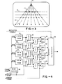
- Figure 1 is an illustration of a video display in an ultrasonic sector scanner.
- the scanner generates a pattern comprised of a plurality of vectors 10 emanating from a vertex 12 defined by the position of the transducer in the scanner.
- Data for the pixels 14 defined by crossing points of the vectors 10 and a display scan line 16 are generated in circuitry which responds to the starting position of each vector and the angle of inclination of the vector.
- FIG. 2 is a functional block diagram of conventional circuitry for generating the pixel data for controlling a display in response to reflected signals for a plurality of vectors.
- One embodiment of such scan converter circuitry is disclosed in U.S. Patent No. 4,236,221.
- the start position for each vector is defined in an X start PROM 20 and a Y start PROM 22.
- the inclination of the vector is provided in a cosine data PROM 24 and a sine data PROM 26 .
- the outputs of the PROMS 20-26 are applied through latches 30-36, respectively, to a vector generator 38 along with the reflected signals for the vectors, and data for pixels of a display are supplied to a memory 40 for use in controlling the electron beam in the video display.
- the PROMS 20-26 are addressed by beam counter 42 which is clocked at each vector start in determining the pixel data for each display frame.
- a certain number of beams and a frame rate are chosen depending on required depth of the scan.
- the number of beams must be reduced as frame rate is increased, and in a dynamic image the frame rate is important.
- a degradation of the picture occurs due to the loss of frame integration by the observer's eye. Therefore, a higher line density is desirable to increase the number of unique pixels in the image.
- the number of pixels in a freeze frame is increased with a second display frame generated by writing the resultant vectors for the first frame offset by one-half vector.
- the offset vectors 11 shown by dotted line
- the offset vectors 11 generate data points 17 illustrated by x's on the horizontal scan line 16 of the video display. Accordingly, a more definite image of the frozen frame is presented.
- Figure 4 is a functional block diagram of apparatus for generating the freeze frame video display in accordance with the invention.
- the circuitry is similar to the circuitry of Figure 2 and like elements have the same reference numerals.
- summers 50, 52, 54, and 56 are interconnected to receive the outputs of the latches 30-36 and the PROMS 20-26, respectively, whereby the second frame can be generated.
- the first frame is generated as in Figure 2, and then the second frame is provided by averaging the data for successive vectors which is then applied through MUX 60-66 to the vector generator 38 thereby generating the vectors 11 lying intermediate adjacent vectors of the first frame.
- the reflected signals for the first frame vectors are used again for the vectors of the second frame to generate the pixel data 17 as shown in Figure 3.
- the multiplexers are set to select the output of the latches 30-36 which generate the vectors described by the content of the PROMS when interfaced to vector generation circuit.
- the multiplexers are set to select the output of the full adders. In this way the offset vectors are generated between the two normal vectors. In a sector scanner these vectors will overlap in the near field but in the far field where the vectors diverge new pixels will be written which will reduce the number of pixels which have to be filled artificially by other means.
- Freeze frames generated by the method in accordance with the invention has proved successful in providing improved images.
- the apparatus is readily implemented in digital sector scanner apparatus such as the Datason system cf General Electric Company. While the invention has been described with reference to a specific embodiment, the description is illustrative of the invention and is not to be construed as limiting the invention. Various modifications and applications may occur to those skilled in the art without departing from the true spirit and scope of the invention as defined by the appended claims.
Landscapes
- Engineering & Computer Science (AREA)
- Computer Networks & Wireless Communication (AREA)
- Physics & Mathematics (AREA)
- General Physics & Mathematics (AREA)
- Radar, Positioning & Navigation (AREA)
- Remote Sensing (AREA)
- Ultra Sonic Daignosis Equipment (AREA)
- Investigating Or Analyzing Materials By The Use Of Ultrasonic Waves (AREA)
- Measurement Of Velocity Or Position Using Acoustic Or Ultrasonic Waves (AREA)
Applications Claiming Priority (2)
| Application Number | Priority Date | Filing Date | Title |
|---|---|---|---|
| US06/290,851 US4386529A (en) | 1981-08-07 | 1981-08-07 | Method and means for improving video display image |
| US290851 | 1981-08-07 |
Publications (2)
| Publication Number | Publication Date |
|---|---|
| EP0071924A2 true EP0071924A2 (fr) | 1983-02-16 |
| EP0071924A3 EP0071924A3 (fr) | 1985-07-31 |
Family
ID=23117806
Family Applications (1)
| Application Number | Title | Priority Date | Filing Date |
|---|---|---|---|
| EP82106935A Withdrawn EP0071924A3 (fr) | 1981-08-07 | 1982-07-31 | Procédé et appareil pour l'amélioration de l'image d'un affichage vidéo |
Country Status (3)
| Country | Link |
|---|---|
| US (1) | US4386529A (fr) |
| EP (1) | EP0071924A3 (fr) |
| JP (1) | JPS5852585A (fr) |
Cited By (2)
| Publication number | Priority date | Publication date | Assignee | Title |
|---|---|---|---|---|
| EP0157302A1 (fr) * | 1984-03-24 | 1985-10-09 | Kabushiki Kaisha Toshiba | Appareil d'imagerie ultrasonore à commande d'échelle |
| FR2593009A1 (fr) * | 1986-01-10 | 1987-07-17 | Thomson Csf | Procede d'homogeneisation d'une image issue d'une conversion de coordonnees et transformateur numerique d'images utilisant un tel procede |
Families Citing this family (8)
| Publication number | Priority date | Publication date | Assignee | Title |
|---|---|---|---|---|
| JPS62179438A (ja) * | 1986-01-31 | 1987-08-06 | ジーイー横河メディカルシステム株式会社 | デイジタル・スキヤンコンバ−タ |
| US4847624A (en) * | 1987-12-30 | 1989-07-11 | Westinghouse Electric Corp. | Coordinate system transformation apparatus for a high resolution radar |
| US5763785A (en) * | 1995-06-29 | 1998-06-09 | Massachusetts Institute Of Technology | Integrated beam forming and focusing processing circuit for use in an ultrasound imaging system |
| US5590658A (en) | 1995-06-29 | 1997-01-07 | Teratech Corporation | Portable ultrasound imaging system |
| US7500952B1 (en) | 1995-06-29 | 2009-03-10 | Teratech Corporation | Portable ultrasound imaging system |
| US8241217B2 (en) | 1995-06-29 | 2012-08-14 | Teratech Corporation | Portable ultrasound imaging data |
| JP4767066B2 (ja) * | 2006-03-31 | 2011-09-07 | 中国電力株式会社 | 埋設物標示装置 |
| US20100228130A1 (en) * | 2009-03-09 | 2010-09-09 | Teratech Corporation | Portable ultrasound imaging system |
Family Cites Families (13)
| Publication number | Priority date | Publication date | Assignee | Title |
|---|---|---|---|---|
| US2921124A (en) * | 1956-12-10 | 1960-01-12 | Bell Telephone Labor Inc | Method and apparatus for reducing television bandwidth |
| US4023165A (en) * | 1975-06-02 | 1977-05-10 | Rca Corporation | Signal modification techniques |
| JPS6024429B2 (ja) * | 1977-08-15 | 1985-06-12 | 沖電気工業株式会社 | デイジタル走査変換方式 |
| US4172386A (en) * | 1977-11-07 | 1979-10-30 | Litton Industrial Products, Inc. | Video A-trace display system for ultrasonic diagnostic system |
| US4204433A (en) * | 1977-11-07 | 1980-05-27 | Litton Industrial Products, Inc. | Computerized ultrasonic scanner with technique-select |
| EP0002061B2 (fr) * | 1977-11-21 | 1986-11-26 | General Electric Company | Convertisseur de balayage pour dispositif de balayage de secteur à ultrasons et procédé |
| DE2820660B1 (de) * | 1978-05-11 | 1979-03-22 | Siemens Ag | Nach dem Impuls-Echoverfahren arbeitendes Ultraschall-Bildgeraet |
| US4262290A (en) * | 1978-05-12 | 1981-04-14 | Smiths Industries Limited | Display systems |
| JPS54151868A (en) * | 1978-05-22 | 1979-11-29 | Toitsu Kogyo Kk | Electronicallyyscanned ultrasonic imaging device |
| US4236221A (en) * | 1978-11-13 | 1980-11-25 | Litton Industrial Products, Inc. | Scan converter |
| JPS5578947A (en) * | 1978-12-08 | 1980-06-14 | Matsushita Electric Industrial Co Ltd | Method of displaying ultrasoniccwave diagnosis device |
| CA1159957A (fr) * | 1980-07-30 | 1984-01-03 | James M. Gessert | Circuit d'interpolation de temps reel |
| DE3045766C2 (de) * | 1980-12-04 | 1984-03-08 | Siemens AG, 1000 Berlin und 8000 München | Verfahren und Vorrichtung zur Darstellung von Ultraschall-Schnittbildern |
-
1981
- 1981-08-07 US US06/290,851 patent/US4386529A/en not_active Expired - Lifetime
-
1982
- 1982-07-31 EP EP82106935A patent/EP0071924A3/fr not_active Withdrawn
- 1982-08-06 JP JP57136447A patent/JPS5852585A/ja active Pending
Cited By (5)
| Publication number | Priority date | Publication date | Assignee | Title |
|---|---|---|---|---|
| EP0157302A1 (fr) * | 1984-03-24 | 1985-10-09 | Kabushiki Kaisha Toshiba | Appareil d'imagerie ultrasonore à commande d'échelle |
| US4614196A (en) * | 1984-03-24 | 1986-09-30 | Kabushiki Kaisha Toshiba | Ultrasonic imaging apparatus using scale control |
| FR2593009A1 (fr) * | 1986-01-10 | 1987-07-17 | Thomson Csf | Procede d'homogeneisation d'une image issue d'une conversion de coordonnees et transformateur numerique d'images utilisant un tel procede |
| EP0233095A1 (fr) * | 1986-01-10 | 1987-08-19 | Thomson-Csf | Transformateur numérique d'images pour homogénéisation d'une image issue d'une conversion de coordonnées. |
| US4774516A (en) * | 1986-01-10 | 1988-09-27 | Thomson-Csf | Method for smoothing an image generated by coordinate conversion and a digital scan converter using the method |
Also Published As
| Publication number | Publication date |
|---|---|
| JPS5852585A (ja) | 1983-03-28 |
| US4386529A (en) | 1983-06-07 |
| EP0071924A3 (fr) | 1985-07-31 |
Similar Documents
| Publication | Publication Date | Title |
|---|---|---|
| Ophir et al. | Digital scan converters in diagnostic ultrasound imaging | |
| US4356731A (en) | Method and means for generating time gain compensation control signal for use in ultrasonic scanner and the like | |
| US4275415A (en) | Scan converter | |
| US4375671A (en) | Method and means for filtering and updating pixel data | |
| US4520671A (en) | Method and means for real time image zoom display in an ultrasonic scanning system | |
| US4386529A (en) | Method and means for improving video display image | |
| US4475400A (en) | Method and means for improving image in an ultrasonic scanning system | |
| US4386528A (en) | Method and means for generating pixel data in an ultrasonic scanning system | |
| US4370646A (en) | Method and means for controlling electron beam in a raster scan monitor | |
| JP2950632B2 (ja) | 超音波診断装置 | |
| US4408228A (en) | Method and means for reducing noise in television display system | |
| US4361043A (en) | Reference voltage generation means for controlling a display | |
| JPS6236693B2 (fr) | ||
| US4448201A (en) | Digital scan converter | |
| KR20080034660A (ko) | 초음파 영상을 형성하는 초음파 시스템 및 방법 | |
| US4837749A (en) | Ultrasonic imaging system for obtaining zoom video images of an object | |
| US4200885A (en) | Ultrasonic scope | |
| US4359728A (en) | Method and means for minimizing distortion in television display | |
| JPH03176040A (ja) | 超音波診断装置 | |
| JPS60168440A (ja) | 超音波診断装置 | |
| US4574636A (en) | Apparatus for examining an object by using ultrasonic beams | |
| JPH0228870B2 (fr) | ||
| JPH04152939A (ja) | 超音波診断装置 | |
| JPH0349691Y2 (fr) | ||
| Matzuk et al. | Ultrasound grey scale display on storage oscilloscope system |
Legal Events
| Date | Code | Title | Description |
|---|---|---|---|
| PUAI | Public reference made under article 153(3) epc to a published international application that has entered the european phase |
Free format text: ORIGINAL CODE: 0009012 |
|
| AK | Designated contracting states |
Designated state(s): DE GB NL |
|
| PUAL | Search report despatched |
Free format text: ORIGINAL CODE: 0009013 |
|
| AK | Designated contracting states |
Designated state(s): DE GB NL |
|
| STAA | Information on the status of an ep patent application or granted ep patent |
Free format text: STATUS: THE APPLICATION IS DEEMED TO BE WITHDRAWN |
|
| 18D | Application deemed to be withdrawn |
Effective date: 19860203 |
|
| RIN1 | Information on inventor provided before grant (corrected) |
Inventor name: ENGLE, GARY LEE |