EP0071936A2 - Aufzeichnungs- und Wiedergabegerät mit Telefonanschluss - Google Patents
Aufzeichnungs- und Wiedergabegerät mit Telefonanschluss Download PDFInfo
- Publication number
- EP0071936A2 EP0071936A2 EP82106963A EP82106963A EP0071936A2 EP 0071936 A2 EP0071936 A2 EP 0071936A2 EP 82106963 A EP82106963 A EP 82106963A EP 82106963 A EP82106963 A EP 82106963A EP 0071936 A2 EP0071936 A2 EP 0071936A2
- Authority
- EP
- European Patent Office
- Prior art keywords
- recording media
- record
- indexing
- recording
- telephone
- Prior art date
- Legal status (The legal status is an assumption and is not a legal conclusion. Google has not performed a legal analysis and makes no representation as to the accuracy of the status listed.)
- Granted
Links
Images




Classifications
-
- G—PHYSICS
- G11—INFORMATION STORAGE
- G11B—INFORMATION STORAGE BASED ON RELATIVE MOVEMENT BETWEEN RECORD CARRIER AND TRANSDUCER
- G11B25/00—Apparatus characterised by the shape of record carrier employed but not specific to the method of recording or reproducing, e.g. dictating apparatus; Combinations of such apparatus
- G11B25/06—Apparatus characterised by the shape of record carrier employed but not specific to the method of recording or reproducing, e.g. dictating apparatus; Combinations of such apparatus using web-form record carriers, e.g. tape
- G11B25/063—Apparatus characterised by the shape of record carrier employed but not specific to the method of recording or reproducing, e.g. dictating apparatus; Combinations of such apparatus using web-form record carriers, e.g. tape using tape inside container
-
- G—PHYSICS
- G11—INFORMATION STORAGE
- G11B—INFORMATION STORAGE BASED ON RELATIVE MOVEMENT BETWEEN RECORD CARRIER AND TRANSDUCER
- G11B15/00—Driving, starting or stopping record carriers of filamentary or web form; Driving both such record carriers and heads; Guiding such record carriers or containers therefor; Control thereof; Control of operating function
- G11B15/675—Guiding containers, e.g. loading, ejecting cassettes
- G11B15/68—Automatic cassette changing arrangements; automatic tape changing arrangements
- G11B15/6845—Automatic cassette changing arrangements; automatic tape changing arrangements with rotatable magazine
- G11B15/685—Automatic cassette changing arrangements; automatic tape changing arrangements with rotatable magazine the cassettes being arranged in a single level
- G11B15/6865—Automatic cassette changing arrangements; automatic tape changing arrangements with rotatable magazine the cassettes being arranged in a single level with a fixed recorder or player under the magazine
-
- G—PHYSICS
- G11—INFORMATION STORAGE
- G11B—INFORMATION STORAGE BASED ON RELATIVE MOVEMENT BETWEEN RECORD CARRIER AND TRANSDUCER
- G11B27/00—Editing; Indexing; Addressing; Timing or synchronising; Monitoring; Measuring tape travel
- G11B27/002—Programmed access in sequence to a plurality of record carriers or indexed parts, e.g. tracks, thereof, e.g. for editing
Definitions
- the present invention relates to dictating equipment which may be remotely operated via telephone lines and to telephone answering devices which automatically answer an incoming call with a predetermined message and subsequently provide a recording apparatus for recording an incoming message.
- the present invention comprises apparatus in which a single mechanical changer apparatus and one set of record/playback electronics interface a plurality of discrete recording media with a plurality of telephone trunk lines.
- the recording media are conventional tape microcassettes.
- a controller places a particular one of the recording media in a recording/playback relationship with the apparatus.
- Selector circuitry in the controller responsive to an incoming call received on a particular one of the telephone lines provides an indexing signal which corresponds to the particular telephone line. Indexing circuitry in the controller then causes the changer apparatus to place a particular one of the recording media into operative relationship with the record/playback electronics.
- the present invention thereby provides a remotely operable telephone interfaced dictation system or a telephone answering apparatus for a plurality of telephone lines having only one transport and one set of record/playback electronics which serves the function of a plurality of conventional dictation recorders.
- the present invention may be used to inexpensively replace a plurality of telephone answering machines for a plurality of distinct telephone trunk lines.
- the present invention is arranged to place one of a plurality of recorded messages on the audio connecting path in response to an incoming call on one of a plurality of telephone trunks.
- the particular message is determined by the particular trunk upon which the incoming call was received.
- the controller automatically indexes a magazine carrying the plurality of recording media to a particular recording medium dedicated to the recording of messages from the incoming calls. Different messages on different media may be placed on different trunks, and incoming messages received on the various trunks are then recorded on still another medium.
- the present invention may also be arranged so that the controller indexes a particular recording medium associated with a particular trunk in response to a call on that particular trunk.
- the selected recording medium is then connected to the audio connecting path and the caller may then operate the transport and record/playback electronics as a remotely operated telephone interfaced dictation recorder.
- An object of the present invention is to provide a mechanical apparatus and electronic controller responsive to a particular trunk upon which an incoming call is received to place a particular one of a plurality of recording media in audio communication with the particular trunk.
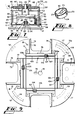
- Fig. 1 shows the cassette changer apparatus 10 which, in conjunction with the control circuitry described hereinbelow, embodies the present invention.
- the changer apparatus 10 includes a rectangular base 12, across which is mounted a pivot rod support member 14 carrying a pivot rod 15.
- a movable L-shaped frame 17 is pivotally attached to the pivot rod 15 by pivot bearings 18.
- a cylindrical cam 23, shown in Figs. 1, 3--5, 7 and 8, is rotatably mounted on the vertical shaft 20.
- the shaft 20 passes through an opening 25 in the upper end of the cam 23, and a cam surface 24 is defined by the edge of the cylinder, seen in Fig. 8.
- a cam follower 28 is mounted on the base 12 and extends through an opening 31 in the movable frame 17 to engage the cam surface 24, as shown in Fig. 7. As the cam rotates, the cam 23 and cam follower 28 cooperate to lift the frame 17 from a lowered position (shown in Figs. 3 and 7) to a raised position (shown in Fig. 4).
- a cam limit switch S2 mounted adjacent to the cam is engaged by a cam trip 27 when the cam 23 (and therefore the frame 17) is in a fully lowered position.
- Another switch S5 is momentarily closed by trip 27 once during early rotation of the cam.
- Cam belt groove 30 about the circumference of the cam receives a cam belt 29 to drive the cam 23 in a clockwise direction.
- a limit switch S4 mounted on the base 12 is closed when the frame 17 is lowered.
- a clutch 32 Immediately above the cam 23 are a clutch 32, a clutch-engaging member 34, and a cartridge support member 35.
- the clutch-engaging member 34 and cartridge support member 35 are together rotatably mounted on the shaft 20.
- a clutch biasing spring 36 biases the cam 23 against the clutch-engaging member 34.
- the cartridge support member 35 rotates with the cam.
- a cartridge locator key 38 positions a cartridge 70 placed on the cartridge support member 35 by extending into an opening 79 in the cartridge.
- the cartridge 70 as shown in Figs. 2, 4 and 9, includes a plurality of tape cassette locations.
- the clutch-engaging member 34 includes four cartridge motion stops 37.
- a cam drive pulley 40 is rotatably mounted on the frame 17 next to the cam 23.
- a small diameter upper member 41 of the pulley 40 carries the cam belt 29.
- a larger diameter lower member 42 of the pulley 40 forms a gear which is driven by a drive gear (not shown) at the base of a DC motor 45.
- a pivot link 53 is pivotally mounted adjacent to the cam 23 on a vertical axle 54 extending upwardly from the frame 17.
- a brake member 53a of pivot link 53 lies in the path of the cartridge motion stops 37
- a trigger member 53b lies in the path of the cam trip 27, as best shown in Figs. 6 and 7.
- the cam trip 27 engages the trigger member 53b, rotating the pivot link 53 against the bias of a spring 55, and removes a brake member 53a from the path of the cartridge motion stops 37.
- the brake member 53a is urged back into place by the spring 55, so that when the next stop 37 arrives at the position of the pivot link 53, the motion of the clutch-engaging member 34 will be arrested.
- a dash pot 57 having a foot 58 biased by a spring 59 eases the frame 17 into a lowered position.
- An "L” shaped pivoted latch 140 can be pivoted under the frame 17 by a solenoid 147 when the frame 17 is in a fully raised position.
- a piston rod 149 extends out of the solenoid 147, causing the arm of the "L" shaped latch 140 to be pivoted under the frame 17.
- Operation of the solenoid 147 and latch 140 allow the operation to change from one cassette location directly to another cassette location not immediately adjacent to the original location, in a manner to be described hereinafter.
- a conventional tape transport deck 62 mounted on legs 61.
- the mechanism includes spindles 63 enclosed in housings 63a, and a capstan 65.
- a tapered locator key 64 engages a cartridge 70 and guides it into proper position with respect to the transport mechanism.
- a movable transducer head assembly 66 includes a pinch roller 67 for engaging the capstan and a record/listen head 68 moves into and out of engagement with a tape cassette in a conventional manner.
- a worm gear 94, axle 95, and axle supports 92 are used in conjunction with the mechanical tape displays described in copending U.S. Application Serial No. 78,231.
- the cassette-carrying cartridge 70 shown in Figs. 2 and 9 includes upper and lower parallel plates 72 and 72a, each including cutouts 73.
- Flexible guides 74 are attached to blocks 77 which attach the parallel plates 72 and 72a to one another and support the guides 74.
- a rear stop 76 is located inwardly of each cutout 73.
- Projections 75 on the guides 74 removably retain a standard microcassette 80 within the cartridge 70 at a fixed cassette location.
- the cutouts 73 are somewhat smaller in area than the cassettes, so that the parallel plates 72 and 72a restrain the cassettes. The openings in the cassettes are exposed for insertion of the rotatable spindles 63 and capstan 65 of the transport mechanism.
- a shaft opening 78 at the center allows the cartridge 70 to be placed over the vertical shaft 20 and to rest upon the cartridge support member 35, as shown in Fig. 4.
- Keyway 79 receives the cartridge locator key 38.
- a positive locator keyway 81 located adjacent each cassette position in the cartridge 70 receives the locator key 64 mounted on the transport deck 62 when the cartridge 70 is lowered onto the tape transport deck 62 and guides the cartridge 70 into precise alignment.
- the mechanical apparatus described above provides the ability to selectively engage, one at a time, a plurality of recording media located in the four cassette positions 73 on cartridge 70 with the transport and record playback head apparatus located on deck 62.
- This mechanical apparatus together with the control circuitry described hereinbelow, comprise a recording medium control means for alternately placing each of a plurality of recording media in recording relationship with transducer 67.
- the control circuitry cooperates with the mechanical elements shown in Figs. 1--9 to provide new and unique telephone answering apparatus and telephone interfaced remote control dictation recorder.
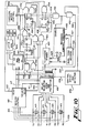
- FIG. 10 control circuitry for a telephone interfaced remote control dictation is shown.
- a plurality of telephone trunk lines 409 provide input.
- Each trunk of trunk lines 409 comprises a tip and ring pair.
- four such tip ring pairs are shown (TO, RO) through (T3, R3).
- Each tip ring pair has a conventional ring detector 415 disposed across the pair which provides a positive voltage on one of lines 416 in response to detecting a ringing signal on the trunk.
- Trunks 409 are provided as inputs to selector circuitry block 418, which comprises conventional relay switching circuitry for connecting one of trunks 409 to transformer 419 and circuitry necessary to comply with Part 68 of the regulations of the Federal Communications Commission, U.S.A.
- the output of relay selector 418 appears on the primary of transformer 419 which couples the AC component of the telephone signal to telephone hybrid 20.
- a logical one on line 411 causes selector 418 to connect one of trunks 409 to the primary of transformer 419.
- Trunk seizure control circuitry 410 provides a two bit binary number on lines 417 which corresponds to the particular one of trunks 409 which will seize the machine.
- Telephone hybrid 420 is coupled to a dual tone decoder 422 which provides a decoded output from conventional dual tone telephone signals to control recorder control functions shown in block 430.
- Lines 427 control conventional recorder functions such as record, playback, fast forward and others.
- the signal of hybrid 420 is also provided along line 428 as the audio input to the conventional control and record/playback electronics shown as block 430.
- the output of the playback amplifier of the recorder is shown as line 429.
- trunk seizure control 410 When an incoming call is received, trunk seizure control 410 provides a two bit number on lines 417 which indicates the particular trunk which is being answered and provides a pulse on line 432 upon seizure of that trunk.
- the pulse on line 432 is provided through one of AND gates 465 and 466 to the direct set input of either flip-flop 436 or 437.
- Flip-flop 436 will set whenever an operating sequence begins and a recording medium which does not correspond to the calling trunk is at deck 62. If the recording medium corresponding to the calling trunk is at deck 62, flip-flop 437 will set.
- All synchronous counters and flip-flops are to be connected to a common high speed clock (not shown) in a conventional manner.
- Flip-flops 436, 437 and gates 442 and 443 comprise a two bit counter 438.
- a logical one at point 439 from NOR gate 441 enables counter 438.
- the 00 state of counter 438 is stable and the counter will not exit this state unless a positive transition from the seize output of trunk seizure control 410 has been provided.
- Each state of lines 417 from seizure control 410 corresponds to one cassette position 73 of cartridge 70.
- Switches 120 and 121 in conjunction with cams 118 and 119 (Fig. 9) detect which of the microcassette positions is engaged with the transport. As cartridge 70 is rotated, cams 118 and 119 close a combination of switches 120 and 121 which provide a direct binary readout corresponding to the cassette position approaching the transport. As may be seen from Fig. 9, a third cam 117 is provided which strobes a third switch S6 (Fig. 1) which is mounted parallel to switches 120 and 121. Switch S6 provides a pulse during each quarter rotation of cartridge 70. This pulse is provided to the strobe input (STB) of latch 445 and latches the states of switches 120 and 121 onto lines 446.
- STB strobe input
- lines 446 comprise one set of inputs to a magnitude comparator 435, the other set of inputs being provided on lines 417 corresponding to the particular trunk which has been seized.
- Dual tone decoder 422 decodes pairs of tones corresponding to depression of particular keys on a standard dual tone telephone, or may be embodied as a dial pulse counter for control of the recorder from rotary dial telephones.
- Conventional telephone hybrid 420 establishes an audio communication path along lines 428 and 429 to and from the audio input and output of the record/playback electronics in block 430.
- the controller for a second embodiment of the present invention is shown in Fig. 11.
- Fig. 11 the same devices which appear in Fig. 10 are referenced with the same numerals.
- the controller of Fig. 11 has only three trunks because three separate messages are provided on three of the microcassettes contained in cartridge 70 while the fourth cassette is used for recording of messages.
- the user of the apparatus records three distinct messages on each of three different microcassettes on cartridge 70. Each distinct message is appropriate for answering one of the three trunks 409.
- the appropriate message cassette is placed in operative relationship with the transport and delivers the prerecorded message to the calling party.
- the controller indexes cartridge 70 to place the cassette dedicated to recording the incoming messages in operative relationship with the transport.
- the controller indexes back to the prerecorded message which has just been delivered, rewinds the microcassette, and waits for the next call.
- Block 448 controlling motor 34 of the mechanical apparatus is shown in detail in Fig. 11. Activation of solenoid 147 causes cartridge 70 to rotate past an approaching cassette. the next output from switch S5 deactivates solenoid 147 and causes the cartridge to be lowered and motor 45 to shut off when cam 27 (Fig. 8) engages the actuator for switch S2.
- trunk seizure detector 410 evidences seizure of one of trunks 409 by providing an output on point 411 to D-type flip-flops 469 and 471, which cause a pulse one clock period wide on line 475. This pulse is provided to the negated parallel enable (PE) input of state counter 468 which causes the counter to load 1001.
- PE negated parallel enable
- the Q1--Q4 bits of counter 468 are provided as the inputs to decoder 480.
- the least significant state bit (Ql) is provided to the K input of flip-flop 481 and is inverted by inverter 478, the output of which is provided along line 479 to AND gate 485 and to the negated clear (CLR) input of delay counter 467.
- the Ql state bit is also provided to line 440 and controls motor 45 which is active to rotate cartridge 70 during odd numbered states of counter 468 only.
- decoder 480 Only even numbered outputs of decoder 480 are provided as inputs to the transport and electronics control block 430, which is operative during even numbered states of counter 468 and inoperative during odd numbered states during which cartridge 70 is being rotated.
- the apparatus removes the zero position cassette from the transport and begins rotation of cartridge 70 until switches 120 and 121 detect the approach of the cassette position corresponding to the particular one of trunks 409 which has been seized.
- Positive transition detector 470 provides a positive going pulse one clock period wide to OR gate 477 upon the approach of the proper cassette.
- Switch S2 opens when the approaching microcassette is lowered into engagement with the transport.
- Counter 468 enters an even state, which allows delay counter 467 to count. When delay counter 467 has counted to its terminal count, flip-flop 481 will set and enable decoder 480.
- Delay counter 467 provides sufficient time to allow cartridge 70 to rotate from the actuation of switch S6 until the cassette is properly lowered into the transport.
- the appropriate recorded message on the cassette engaged with the transport is then played over line 429, amplified by summing amplifier 486, and provided to telephone hybrid 420.
- a tone of predetermined frequency fl is recorded at the end of each outgoing message.
- each message Prior to provision of the fl tone each message should terminate by an audible instruction to the caller to leave a message upon the occurrence of an audible tone. It is therefore preferred that the tone of frequency of fl be inaudible to the calling party.
- fl tone detector 487 which in the second preferred embodiment is a type 567 phase lock loop tone decoder having an output which goes low upon the detection of a tone which falls within the predetermined lock range of the detector. This output is damped by an RC network designed to damp out spurious locks.
- OR gate 488 When a true lock condition is detected the output is inverted and provided as an input to OR gate 488 at the input of transition detector 476 which provides a pulse to OR gate 477 enabling state counter 468 to count to its next state.
- a logical one appears on line 496 which activates the record function of transport and electronics control block 430 and triggers one shot 491.
- One shot 491 turns on an oscillator 493 which provides an audible tone of predetermined frequency which signals the calling party that the recorder is ready to accept and record an incoming message.
- the apparatus remains in its four (100) state until the calling party hangs up.
- the idle condition of the trunk is detected by idle detector 458 and AND gate 452, causing counter 468 to count to its five (101) state.
- motor 45 rotates cartridge 70 until the message cassette corresponding to the trunk upon which the call was received is again encountered.
- the outgoing message cassette will then be lowered into operative connection with the transport.
- the six (110) state of counter 468 activates the rewind function on transport and electronics control block 430 and also triggers one shot 497.
- the output of one shot 497 is provided to AND gate 498.
- the output of AND gate 498 is damped by RC network 484.
- the remaining input to AND gate 498 is an absence of motion detection signal which appears on line 495 from the transport and electronics control block 430.
- the period of one shot 497 allows mechanical inertia of the transport spindle motor (not shown) to be overcome during the rewind operation.
- OR gate 488 allows state counter 468 to count to its seven count (111).
- the seven state being an odd numbered state, causes motor 45 to become operational to index the zero position (incoming message recording) cassette and cause a transition to appear at the output of AND gate 490. This transition causes the counter to count over to its 00 state. After the delay from delay counter 467, the zero output of decoder 480 is provided to line 412, resetting trunk seizure detector 410.
- the apparatus of the second preferred embodiment leaves the zero cassette engaged with the transport.
- Ari embodiment of seizure control apparatus 410 is shown in Fig. 12.
- the outputs of rign detectors 415 are provided on lines 416 as the inputs to a latch 510.
- the outputs of latch 510 are provided as the four lowest order inputs to a priority encoder 515, a type CD-4532B CMOS eight bit priority encoder currently manufactured by RCA, which provides a two bit encoded output on lines 417 corresponding to the highest order one of inputs DO--D3 (D3 being highest priority) having a one thereon.
- This arrangement allows telephone lines 409 to be prioritized in the event of simultaneous ringing.
- Switch 516 allows selective connection of the DO input of encoder 515 to either the lowest priority trunk for the embodiment of Fig. 10 or to ground for the embodiment of Fig. 11.
- the GS output of encoder 515 on line 518 goes high in the event that one of the inputs goes high.
- the output on line 518 is delayed by delay element 520, which then sets flip-flop 521 and causes a pulse to appear on line 522 strobing latch 510.
- Flip-flop 521 also triggers one shot 526, whose output appears at the seize output 432 of seizure control apparatus 410 as shown in Figs. 10 and 11.
- a logical one on line 412 resets seizure control apparatus 410.
- Line 412 is connected to positive transition detector 536 which provides a pulse one clock period wide on line 538 resetting flip-flop 521.
- Transition detector 536 amy be identical to detectors 470 and 476 shown on Fig. 11.
Landscapes
- Telephone Set Structure (AREA)
- Indexing, Searching, Synchronizing, And The Amount Of Synchronization Travel Of Record Carriers (AREA)
- Telephone Function (AREA)
- Recording Or Reproducing By Magnetic Means (AREA)
- Sub-Exchange Stations And Push- Button Telephones (AREA)
- Signal Processing For Digital Recording And Reproducing (AREA)
Priority Applications (1)
| Application Number | Priority Date | Filing Date | Title |
|---|---|---|---|
| AT82106963T ATE30802T1 (de) | 1981-08-03 | 1982-08-02 | Aufzeichnungs- und wiedergabegeraet mit telefonanschluss. |
Applications Claiming Priority (2)
| Application Number | Priority Date | Filing Date | Title |
|---|---|---|---|
| US06/290,951 US4515995A (en) | 1979-09-24 | 1981-08-03 | Telephone answering machine with apparatus for selecting particular outgoing message in response to incoming call on a particular line |
| US290951 | 1981-08-03 |
Publications (3)
| Publication Number | Publication Date |
|---|---|
| EP0071936A2 true EP0071936A2 (de) | 1983-02-16 |
| EP0071936A3 EP0071936A3 (en) | 1984-02-22 |
| EP0071936B1 EP0071936B1 (de) | 1987-11-11 |
Family
ID=23118184
Family Applications (1)
| Application Number | Title | Priority Date | Filing Date |
|---|---|---|---|
| EP82106963A Expired EP0071936B1 (de) | 1981-08-03 | 1982-08-02 | Aufzeichnungs- und Wiedergabegerät mit Telefonanschluss |
Country Status (6)
| Country | Link |
|---|---|
| US (1) | US4515995A (de) |
| EP (1) | EP0071936B1 (de) |
| JP (1) | JPS5875400U (de) |
| AT (1) | ATE30802T1 (de) |
| CA (1) | CA1185721A (de) |
| DE (2) | DE71936T1 (de) |
Cited By (2)
| Publication number | Priority date | Publication date | Assignee | Title |
|---|---|---|---|---|
| GB2193368A (en) * | 1986-07-31 | 1988-02-03 | Ozen Corp | Index carrier for record discs and sound reproducing device |
| EP0389199A3 (de) * | 1989-03-20 | 1991-03-20 | Mitsubishi Denki Kabushiki Kaisha | Automatisches Kassettenbandaufnahme- und -wiedergabegerät |
Families Citing this family (12)
| Publication number | Priority date | Publication date | Assignee | Title |
|---|---|---|---|---|
| US4626631A (en) * | 1985-05-28 | 1986-12-02 | Fortel, Inc. | Dual line adapter for telephone answering machine |
| US4951307A (en) * | 1989-07-13 | 1990-08-21 | Willard Dan E | Method and apparatus for recording telephone messages |
| JPH06276267A (ja) * | 1993-03-23 | 1994-09-30 | Matsushita Electric Ind Co Ltd | 留守番電話装置 |
| US5396544A (en) * | 1993-10-25 | 1995-03-07 | General Research Of Electronics, Inc. | Telephone answering system |
| US5528669A (en) * | 1994-07-06 | 1996-06-18 | Kingtronics Industrial Co., Ltd. | Single cassette answering machine with dual phone line and mailbox features |
| US6823184B1 (en) | 2000-09-08 | 2004-11-23 | Fuji Xerox Co., Ltd. | Personal digital assistant for generating conversation utterances to a remote listener in response to a quiet selection |
| US7106852B1 (en) | 2000-09-08 | 2006-09-12 | Fuji Xerox Co., Ltd. | Telephone accessory for generating conversation utterances to a remote listener in response to a quiet selection |
| US7013279B1 (en) * | 2000-09-08 | 2006-03-14 | Fuji Xerox Co., Ltd. | Personal computer and scanner for generating conversation utterances to a remote listener in response to a quiet selection |
| US7286649B1 (en) | 2000-09-08 | 2007-10-23 | Fuji Xerox Co., Ltd. | Telecommunications infrastructure for generating conversation utterances to a remote listener in response to a quiet selection |
| US6941342B1 (en) | 2000-09-08 | 2005-09-06 | Fuji Xerox Co., Ltd. | Method for generating conversation utterances to a remote listener in response to a quiet selection |
| US6697470B2 (en) | 2001-03-28 | 2004-02-24 | Mcdonough Steven D. | Incoming call indicator |
| US7546143B2 (en) | 2001-12-18 | 2009-06-09 | Fuji Xerox Co., Ltd. | Multi-channel quiet calls |
Family Cites Families (14)
| Publication number | Priority date | Publication date | Assignee | Title |
|---|---|---|---|---|
| US2571973A (en) * | 1946-08-19 | 1951-10-16 | Westinghouse Air Brake Co | Annunciator |
| US2824907A (en) * | 1954-10-06 | 1958-02-25 | Gen Telephone Lab Inc | Multi-channel message announcer for use in telephone systems |
| GB1058253A (en) * | 1962-10-15 | 1967-02-08 | Shipton Electronics Ltd | Improvements in or relating to telephone answering machines |
| AT272689B (de) * | 1967-06-16 | 1969-07-10 | Philips Nv | Tonbandwechsler |
| DE2009024A1 (de) * | 1969-02-26 | 1970-11-05 | Learning Appliances Ltd., London | Telefonanrufbeantworter |
| US3698722A (en) * | 1970-09-21 | 1972-10-17 | Itsuki Ban | Control circuit for multiple tape cartridge playing apparatus |
| US3833186A (en) * | 1972-11-24 | 1974-09-03 | Data Time | Telephone answering device |
| US3904836A (en) * | 1973-02-01 | 1975-09-09 | Lanier Electronic Lab Inc | Apparatus for preferential selection and switching of plural recording machines |
| GB1499320A (en) * | 1974-12-03 | 1978-02-01 | Butler A | Apparatus for the automatic control of magnetic tape |
| AU518495B2 (en) * | 1976-07-16 | 1981-10-01 | Consolidated Electronic Industries Pty. Ltd. | Automatic tape cartridge selection, handling and replay apparatus |
| US4164765A (en) * | 1977-12-07 | 1979-08-14 | National Computer Systems, Inc. | Carousel tape system |
| US4247876A (en) * | 1978-12-18 | 1981-01-27 | Lanier Business Products, Inc. | Dictation recording and transcribing system utilizing a multiple media cartridge apparatus |
| US4221938A (en) * | 1979-03-26 | 1980-09-09 | Lanier Business Products, Inc. | Central control system for a dictation device with plural dictators and plural recorders |
| US4271440A (en) * | 1979-04-06 | 1981-06-02 | International Tapetronics Corporation | Automatic tape cartridge handling system |
-
1981
- 1981-08-03 US US06/290,951 patent/US4515995A/en not_active Expired - Lifetime
-
1982
- 1982-06-28 CA CA000406088A patent/CA1185721A/en not_active Expired
- 1982-08-02 EP EP82106963A patent/EP0071936B1/de not_active Expired
- 1982-08-02 DE DE198282106963T patent/DE71936T1/de active Pending
- 1982-08-02 AT AT82106963T patent/ATE30802T1/de not_active IP Right Cessation
- 1982-08-02 DE DE8282106963T patent/DE3277658D1/de not_active Expired
- 1982-08-03 JP JP1982117472U patent/JPS5875400U/ja active Pending
Cited By (5)
| Publication number | Priority date | Publication date | Assignee | Title |
|---|---|---|---|---|
| GB2193368A (en) * | 1986-07-31 | 1988-02-03 | Ozen Corp | Index carrier for record discs and sound reproducing device |
| GB2193368B (en) * | 1986-07-31 | 1990-04-04 | Ozen Corp | Index carrier for record discs and sound reproducing device |
| EP0389199A3 (de) * | 1989-03-20 | 1991-03-20 | Mitsubishi Denki Kabushiki Kaisha | Automatisches Kassettenbandaufnahme- und -wiedergabegerät |
| US5148332A (en) * | 1989-03-20 | 1992-09-15 | Mitsubishi Denki Kabushiki Kaisha | Automatic cassette tape recording and reproducing apparatus with a pivotable magazine holder |
| EP0569105A3 (en) * | 1989-03-20 | 1994-05-11 | Mitsubishi Electric Corp | Automatic cassette tape recording and reproducing apparatus |
Also Published As
| Publication number | Publication date |
|---|---|
| ATE30802T1 (de) | 1987-11-15 |
| US4515995A (en) | 1985-05-07 |
| CA1185721A (en) | 1985-04-16 |
| DE3277658D1 (en) | 1987-12-17 |
| JPS5875400U (ja) | 1983-05-21 |
| DE71936T1 (de) | 1983-09-15 |
| EP0071936A3 (en) | 1984-02-22 |
| EP0071936B1 (de) | 1987-11-11 |
Similar Documents
| Publication | Publication Date | Title |
|---|---|---|
| EP0071936B1 (de) | Aufzeichnungs- und Wiedergabegerät mit Telefonanschluss | |
| JPS63114356A (ja) | モジュ−ル式の口述/筆記システム | |
| US3673332A (en) | Telephone answering devices | |
| JPS56158561A (en) | Automatic answering telephone set | |
| US3067289A (en) | Integrating control timer | |
| US3127474A (en) | Telephone answering apparatus | |
| US3721765A (en) | Telephone answering machine | |
| US4263481A (en) | Automatic telephone answering and recording apparatus | |
| CA1232694A (en) | Automatic telephone answering apparatus | |
| US4230909A (en) | Telephone answering machine | |
| US4720846A (en) | Automatic telephone answering and recording apparatus | |
| US3860963A (en) | Plural tape recorder change-over mechanism for simultaneous or sequential operation | |
| US3383469A (en) | Telephone answering devices with remote control | |
| US4620065A (en) | Automatic telephone answering and recording apparatus | |
| US4390752A (en) | Ring detection circuit for a telephone answering device | |
| US4340784A (en) | Portable telephone answering device | |
| US3903368A (en) | Telephone automatic answering device with plural message recorders | |
| US3790722A (en) | Magnetic tape cartridge dialer | |
| US4519009A (en) | Dictation recording and transcribing system utilizing a multiple media cartridge apparatus | |
| US4236044A (en) | Remote playout control mechanism for a telephone answering device | |
| US4445000A (en) | Automatic telephone answering apparatus | |
| US3700818A (en) | Automatic answering telephone set | |
| EP0216528B1 (de) | Automatischer Telefonanrufbeantworter | |
| JP2502538B2 (ja) | 留守番電話装置 | |
| US5528669A (en) | Single cassette answering machine with dual phone line and mailbox features |
Legal Events
| Date | Code | Title | Description |
|---|---|---|---|
| PUAI | Public reference made under article 153(3) epc to a published international application that has entered the european phase |
Free format text: ORIGINAL CODE: 0009012 |
|
| AK | Designated contracting states |
Designated state(s): AT BE CH DE FR GB LI NL SE |
|
| TCAT | At: translation of patent claims filed | ||
| TCNL | Nl: translation of patent claims filed | ||
| EL | Fr: translation of claims filed | ||
| DET | De: translation of patent claims | ||
| 17P | Request for examination filed |
Effective date: 19830720 |
|
| PUAL | Search report despatched |
Free format text: ORIGINAL CODE: 0009013 |
|
| AK | Designated contracting states |
Designated state(s): AT BE CH DE FR GB LI NL SE |
|
| 17Q | First examination report despatched |
Effective date: 19860207 |
|
| D17Q | First examination report despatched (deleted) | ||
| GRAA | (expected) grant |
Free format text: ORIGINAL CODE: 0009210 |
|
| AK | Designated contracting states |
Kind code of ref document: B1 Designated state(s): AT BE CH DE FR GB LI NL SE |
|
| PG25 | Lapsed in a contracting state [announced via postgrant information from national office to epo] |
Ref country code: FR Free format text: THE PATENT HAS BEEN ANNULLED BY A DECISION OF A NATIONAL AUTHORITY Effective date: 19871111 |
|
| REF | Corresponds to: |
Ref document number: 30802 Country of ref document: AT Date of ref document: 19871115 Kind code of ref document: T |
|
| REF | Corresponds to: |
Ref document number: 3277658 Country of ref document: DE Date of ref document: 19871217 |
|
| EN | Fr: translation not filed | ||
| PG25 | Lapsed in a contracting state [announced via postgrant information from national office to epo] |
Ref country code: GB Free format text: LAPSE BECAUSE OF NON-PAYMENT OF DUE FEES Effective date: 19880802 |
|
| PLBE | No opposition filed within time limit |
Free format text: ORIGINAL CODE: 0009261 |
|
| STAA | Information on the status of an ep patent application or granted ep patent |
Free format text: STATUS: NO OPPOSITION FILED WITHIN TIME LIMIT |
|
| 26N | No opposition filed | ||
| PG25 | Lapsed in a contracting state [announced via postgrant information from national office to epo] |
Ref country code: DE Effective date: 19890503 |
|
| GBPC | Gb: european patent ceased through non-payment of renewal fee | ||
| PGFP | Annual fee paid to national office [announced via postgrant information from national office to epo] |
Ref country code: AT Payment date: 19920714 Year of fee payment: 11 |
|
| PGFP | Annual fee paid to national office [announced via postgrant information from national office to epo] |
Ref country code: SE Payment date: 19920720 Year of fee payment: 11 |
|
| PGFP | Annual fee paid to national office [announced via postgrant information from national office to epo] |
Ref country code: CH Payment date: 19920721 Year of fee payment: 11 |
|
| PGFP | Annual fee paid to national office [announced via postgrant information from national office to epo] |
Ref country code: BE Payment date: 19920723 Year of fee payment: 11 |
|
| PGFP | Annual fee paid to national office [announced via postgrant information from national office to epo] |
Ref country code: NL Payment date: 19920831 Year of fee payment: 11 |
|
| PG25 | Lapsed in a contracting state [announced via postgrant information from national office to epo] |
Ref country code: AT Effective date: 19930802 |
|
| PG25 | Lapsed in a contracting state [announced via postgrant information from national office to epo] |
Ref country code: SE Effective date: 19930803 |
|
| PG25 | Lapsed in a contracting state [announced via postgrant information from national office to epo] |
Ref country code: LI Effective date: 19930831 Ref country code: CH Effective date: 19930831 Ref country code: BE Effective date: 19930831 |
|
| BERE | Be: lapsed |
Owner name: LANIER BUSINESS PRODUCTS INC. Effective date: 19930831 |
|
| PG25 | Lapsed in a contracting state [announced via postgrant information from national office to epo] |
Ref country code: NL Effective date: 19940301 |
|
| NLV4 | Nl: lapsed or anulled due to non-payment of the annual fee | ||
| REG | Reference to a national code |
Ref country code: CH Ref legal event code: PL |
|
| EUG | Se: european patent has lapsed |
Ref document number: 82106963.0 Effective date: 19940310 |