EP0072073A1 - Vorrichtung um eine nicht koherente Masse in einen Ballen zu pressen - Google Patents
Vorrichtung um eine nicht koherente Masse in einen Ballen zu pressen Download PDFInfo
- Publication number
- EP0072073A1 EP0072073A1 EP82200984A EP82200984A EP0072073A1 EP 0072073 A1 EP0072073 A1 EP 0072073A1 EP 82200984 A EP82200984 A EP 82200984A EP 82200984 A EP82200984 A EP 82200984A EP 0072073 A1 EP0072073 A1 EP 0072073A1
- Authority
- EP
- European Patent Office
- Prior art keywords
- drum
- inlet opening
- opening
- stock container
- guide
- Prior art date
- Legal status (The legal status is an assumption and is not a legal conclusion. Google has not performed a legal analysis and makes no representation as to the accuracy of the status listed.)
- Granted
Links
- 230000001427 coherent effect Effects 0.000 title claims description 3
- 238000005192 partition Methods 0.000 claims description 24
- 230000008878 coupling Effects 0.000 claims description 6
- 238000010168 coupling process Methods 0.000 claims description 6
- 238000005859 coupling reaction Methods 0.000 claims description 6
- 230000002093 peripheral effect Effects 0.000 claims description 3
- 238000007789 sealing Methods 0.000 claims description 3
- 230000000903 blocking effect Effects 0.000 claims description 2
- 230000006835 compression Effects 0.000 abstract description 7
- 238000007906 compression Methods 0.000 abstract description 7
- 230000004075 alteration Effects 0.000 abstract description 3
- 238000004519 manufacturing process Methods 0.000 abstract description 2
- 239000000463 material Substances 0.000 description 2
- 230000000694 effects Effects 0.000 description 1
- 230000000737 periodic effect Effects 0.000 description 1
- 239000007787 solid Substances 0.000 description 1
Images

Classifications
-
- B—PERFORMING OPERATIONS; TRANSPORTING
- B30—PRESSES
- B30B—PRESSES IN GENERAL
- B30B9/00—Presses specially adapted for particular purposes
- B30B9/30—Presses specially adapted for particular purposes for baling; Compression boxes therefor
- B30B9/3042—Containers provided with, or connectable to, compactor means
-
- A—HUMAN NECESSITIES
- A01—AGRICULTURE; FORESTRY; ANIMAL HUSBANDRY; HUNTING; TRAPPING; FISHING
- A01F—PROCESSING OF HARVESTED PRODUCE; HAY OR STRAW PRESSES; DEVICES FOR STORING AGRICULTURAL OR HORTICULTURAL PRODUCE
- A01F15/00—Baling presses for straw, hay or the like
- A01F15/02—Baling presses for straw, hay or the like with press-boxes
-
- A—HUMAN NECESSITIES
- A01—AGRICULTURE; FORESTRY; ANIMAL HUSBANDRY; HUNTING; TRAPPING; FISHING
- A01F—PROCESSING OF HARVESTED PRODUCE; HAY OR STRAW PRESSES; DEVICES FOR STORING AGRICULTURAL OR HORTICULTURAL PRODUCE
- A01F15/00—Baling presses for straw, hay or the like
- A01F15/08—Details
- A01F15/10—Feeding devices for the crop material e.g. precompression devices
Definitions
- the invention relates to a device for compressing into a packet a mass of stalks, stems, blades or another more or less loosely coherent mass, for example, hay.
- Such a device has a compression space in which a piston is adapted to reciprocate, whilst means are provided for feeding the mass to be compressed to the compression space bounded by the cylinder and the piston.
- a device has the disadvantage that the reciprocatory movement brings about heavy, periodic alterations of force, whilst in addition the mass distribution and hence the equilibrium of the device are periodically disturbed.
- the mass contained in the compression space is periodically compressed and discharged, which involves an unnecessary input and output of air.
- the invention has for its object to construct a compression device in a manner such that said force alterations will occur hardly or not at all and, moreover, disturbances of the equilibrium which might give rise to shaking or rocking of the device cannot occur.
- a further object of the invention is to provide a device in which the compressing operation takes place substantially continuously so that in addition the production of noise can be limited to a very low level.
- the invention proposes a device of the kind set forth in the preamble which comprises a stock container having an inlet opening, an intermediate wall movable inside said stock container away from and towards said opening and subjected to pressure in the direction towards said opening and a pressing member for a pressurized supply of said mass to the inlet opening.
- a practical embodiment of the device according to the invention is characterized in that the pressing member comprises a cylindrical drum or part thereof having an inlet opening and a longitudinal opening adjoining the inlet opening of the stock container, in which drum is coaxially arranged a drivable rotor having a plurality of substantially radially extending partitions, in that at or near the free longitudinal edge of each partition there is arranged a displacer adapted to swing about an axis parallel to said edge and having an active pressing face adapted to swing towards the drum wall, in that the radial partitions and the displacer are formed and adapted to co-operate in a manner such that the free longitudinal edge-of each partition is in sealing relationship to the partition next to.:the former in the direction opposite the direction of rotation of the rotor and in that there is provided a guide member which gradually urges each displacer towards the drum wall during its movement away from the inlet opening of the drum towards the longitudinal opening thereof.
- the guide member may be designed in the form of at least one at least slightly circular guide rail arranged on a drum head wall, the centre of said rail being located between the drum axis and the inlet opening of the stock container, whilst each displacer is provided with a guide element co-operating with the or each guide rail.
- the rotor may be advantageously constructed so that it has a low mass.
- the or each displacer may be designed in the form of a partition, the free peripheral edge of which is provided with a plate forming a seal with the radial partition following next against the direction of rotation of the rotor.
- the stock container comprises a hood and a trough pivotable with respect to the former between an upper, closed position and an opened position whilst locking means are provided for moving and/or holding the trough in the closed state.
- the locking means are unlocked so that the compressed mass slides down the now sloping bottom of the trough.
- the locking means may comprise at least one spring.
- a fully automatic operation can be carried out by means of a device which is characterized in that the intermediate wall is provided with at least one coupling hook co-operating with at least'one guide at the hood and a corre ⁇ sponding guide at the trough and, as the case may be, provided with rollers for blocking the downward movement of the trough prior to passing by a position of the intermediate wall corresponding to the end of the or each guide.
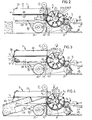
- the device 1 illustrated in the drawing comprises a stock container 2 having an inlet opening 3, an intermediate wall 5 movable inside said stock container 2 away from and towards the opening 3 and subjected to the pressure of the air spring 4 towards said opening 3 and a pressing member 6 for supplying under pressure to the inlet opening 3 a mass 48 lifted from the ground by pick-up means 7 and formed by stalks, stems, blades, hay or the like.
- the pressing member 6 comprises a drum part 8 having an inlet opening 9 and a longitudinal opening 10 adjoining the inlet opening 3 of the stock container 2, in which drum part 8 is coaxially arranged a drivable rotor 11 having a plurality of substantially radially extending partitions 12.
- a partition 14 adapted to swing about an axis parallel to said edge 13 and having the same radius of curvature as the drum part 8, whilst the free peripheral edge 15 of each partition 14 is provided with an inwardly extending plate 16, the axis of curvature of which coincides with the pivotal axis of the partition 14.
- the radial partitions 12 each have a cylindrical part 17, the axis of curvature of which also coincides with the pivotal axis of the partitions 14.
- the pick-up means 7 comprise a rotatably drivable pick-up rake 18 having fingers 21 that can protrude through elongate holes 19 in a drum 20 and that convey stalks, stems or the like to be compressed, picked up from the ground in the direction indicated by the arrows towards a rotatably drivable feeding member 22, which has basically the same structure as the rotatable pick-up rake 18. Over and across a curved plate 23 the material emanating from the pick-up rake is supplied by the feeding member 22 via the inlet opening 9 to the pressing member 6.
- a slightly circular guide rail 23 On the head- walls (not shown) of the drum part 8 is arranged a slightly circular guide rail 23, the centre of which is located between the drum axis and the inlet opening 3 of the stock container 2, whereas at the ends of the plates 16 directed towards the drum head walls rollers are provided which co-operate with the guide rail 23.
- This assembly ensures that during its movement away from the inlet opening 9 up to the longitudinal opening 10 each partition 14 is gradually urged with its active pressing face directed towards the drum part 8 towards the drum wall. It will be clearly apparent from these Figures that during the said movement the compression chamber bounded by the partitions 14, the cylindrical parts 17 of the radial partitions 12 and the drum part 8 becomes gradually smaller as a result of which the introduced material is compressed. Thus an already compressed mass is fed to the stock container 2.
- the stock container 2 comprises a hood 27 fastened to a frame 26 supported by wheels 25 and a trough 28 adapted to pivot with respect to said hood and pivotally supported at the front by a pivotal shaft 29, whilst the bottom is supported by an air spring 30 coupled with the frame 26.
- the device 1 is in this embodiment provided with means for entwining the compressed mass.
- Said means comprise a plurality of stock reels 43 for entwining tape 44 and entwining needles 45 co-operating with said reels and being movable in upward and downward directions.
- This mechanism is known per se and will, therefore, not be discussed in detail. It is designed to tie up the two tape ends and to subsequently form a new loop around a bale to be formed.
- the device 1 is provided at the front with hitching means for being drawn in the direction of the arrow 47 by an agricultural tractor.
- the displacers may be formed by more solid masses.
- the rotor may furthermore comprise a fly-wheel serving as an energy buffer so that the driving motor (not shown) is very uniformly loaded.
Landscapes
- Life Sciences & Earth Sciences (AREA)
- Environmental Sciences (AREA)
- Engineering & Computer Science (AREA)
- Mechanical Engineering (AREA)
- Filling Or Emptying Of Bunkers, Hoppers, And Tanks (AREA)
- Basic Packing Technique (AREA)
- Reduction Or Emphasis Of Bandwidth Of Signals (AREA)
- Photoreceptors In Electrophotography (AREA)
- Auxiliary Devices For And Details Of Packaging Control (AREA)
- Refuse Collection And Transfer (AREA)
- Soil Working Implements (AREA)
Priority Applications (1)
| Application Number | Priority Date | Filing Date | Title |
|---|---|---|---|
| AT82200984T ATE12332T1 (de) | 1981-08-12 | 1982-07-30 | Vorrichtung um eine nicht koherente masse in einen ballen zu pressen. |
Applications Claiming Priority (2)
| Application Number | Priority Date | Filing Date | Title |
|---|---|---|---|
| NL8103783 | 1981-08-12 | ||
| NL8103783A NL8103783A (nl) | 1981-08-12 | 1981-08-12 | Inrichting voor het tot een pakket samenpersen van een min of meer los samenhangende massa. |
Publications (2)
| Publication Number | Publication Date |
|---|---|
| EP0072073A1 true EP0072073A1 (de) | 1983-02-16 |
| EP0072073B1 EP0072073B1 (de) | 1985-03-27 |
Family
ID=19837918
Family Applications (1)
| Application Number | Title | Priority Date | Filing Date |
|---|---|---|---|
| EP82200984A Expired EP0072073B1 (de) | 1981-08-12 | 1982-07-30 | Vorrichtung um eine nicht koherente Masse in einen Ballen zu pressen |
Country Status (6)
| Country | Link |
|---|---|
| US (1) | US4464889A (de) |
| EP (1) | EP0072073B1 (de) |
| AT (1) | ATE12332T1 (de) |
| CA (1) | CA1198011A (de) |
| DE (1) | DE3262791D1 (de) |
| NL (1) | NL8103783A (de) |
Cited By (3)
| Publication number | Priority date | Publication date | Assignee | Title |
|---|---|---|---|---|
| EP0487232A3 (en) * | 1990-11-21 | 1992-07-29 | Woodbury S. Ransom | Hay baler |
| EP0555937A1 (de) * | 1992-02-14 | 1993-08-18 | N.V. Nederlandsche Apparatenfabriek NEDAP | Dosiervorrichtung für Futter |
| FR2800569A1 (fr) * | 1999-11-09 | 2001-05-11 | Jean Jacques Goubin | Presse a fourrage pour la constitution de balles |
Families Citing this family (8)
| Publication number | Priority date | Publication date | Assignee | Title |
|---|---|---|---|---|
| US4559770A (en) * | 1983-05-25 | 1985-12-24 | Sperry Corporation | Round baler with dual function finger drum |
| NL8302489A (nl) * | 1983-07-12 | 1985-02-01 | Multinorm Bv | Pers voor landbouwgewassen. |
| US4846055A (en) * | 1988-03-02 | 1989-07-11 | Mustard Larry D | Baling machine and method of forming a bale |
| US5377481A (en) * | 1993-03-17 | 1995-01-03 | Sibley; Duane L. | Apparatus for baling bulk fibrous material |
| US5479766A (en) * | 1994-07-06 | 1996-01-02 | Ransom; Woodbury S. | Baling apparatus and method |
| US8381503B2 (en) * | 2011-05-31 | 2013-02-26 | Cnh Canada, Ltd. | Intermeshed feeding system for round balers |
| CN103181268B (zh) * | 2013-03-22 | 2015-04-08 | 沈阳工业大学 | 一种韭菜计量捆扎装置 |
| US10595464B2 (en) | 2014-12-02 | 2020-03-24 | Mchale Engineering | Continuous round baler |
Citations (4)
| Publication number | Priority date | Publication date | Assignee | Title |
|---|---|---|---|---|
| DE104240C (de) * | ||||
| FR558862A (fr) * | 1922-11-20 | 1923-09-04 | Compresseur de fourrages, pailles, etc., permettant la réalisation d'un rateau-lieur et d'une moissonneuse-batteuse-lieuse | |
| FR590729A (fr) * | 1924-02-13 | 1925-06-22 | Emidecau | Poussoir rotatif continu à pelles éclipsantes |
| NL7705116A (nl) * | 1976-05-11 | 1977-11-15 | Howard Machinery Ltd | Inrichting voor het vervaardigen van balen. |
Family Cites Families (7)
| Publication number | Priority date | Publication date | Assignee | Title |
|---|---|---|---|---|
| US698566A (en) * | 1901-02-23 | 1902-04-29 | Reuben Shirreffs | Snow-compressing machine. |
| CA104240A (en) * | 1907-01-31 | 1907-03-19 | James Henry Dunstan | Bottle |
| US1496363A (en) * | 1921-06-11 | 1924-06-03 | Bonnafoux Paul | Automatic hay baler |
| DE849028C (de) * | 1951-02-28 | 1952-09-11 | & Eisengiesserei Lauingen Koed | Strohpresse |
| US3889588A (en) * | 1972-03-17 | 1975-06-17 | Philip Wollersheim | Material compacting device |
| US4104853A (en) * | 1975-10-28 | 1978-08-08 | Howard Machinery Limited | Hay baler |
| NL7512991A (nl) * | 1975-11-05 | 1977-05-09 | Multinorm Bv | Inrichting voor het tot bundels persen van ge- maaid landbouwgewas. |
-
1981
- 1981-08-12 NL NL8103783A patent/NL8103783A/nl not_active Application Discontinuation
-
1982
- 1982-07-30 AT AT82200984T patent/ATE12332T1/de not_active IP Right Cessation
- 1982-07-30 US US06/403,364 patent/US4464889A/en not_active Expired - Lifetime
- 1982-07-30 EP EP82200984A patent/EP0072073B1/de not_active Expired
- 1982-07-30 DE DE8282200984T patent/DE3262791D1/de not_active Expired
- 1982-08-11 CA CA000409227A patent/CA1198011A/en not_active Expired
Patent Citations (4)
| Publication number | Priority date | Publication date | Assignee | Title |
|---|---|---|---|---|
| DE104240C (de) * | ||||
| FR558862A (fr) * | 1922-11-20 | 1923-09-04 | Compresseur de fourrages, pailles, etc., permettant la réalisation d'un rateau-lieur et d'une moissonneuse-batteuse-lieuse | |
| FR590729A (fr) * | 1924-02-13 | 1925-06-22 | Emidecau | Poussoir rotatif continu à pelles éclipsantes |
| NL7705116A (nl) * | 1976-05-11 | 1977-11-15 | Howard Machinery Ltd | Inrichting voor het vervaardigen van balen. |
Cited By (6)
| Publication number | Priority date | Publication date | Assignee | Title |
|---|---|---|---|---|
| EP0487232A3 (en) * | 1990-11-21 | 1992-07-29 | Woodbury S. Ransom | Hay baler |
| US5193449A (en) * | 1990-11-21 | 1993-03-16 | Ransom Woodbury S | Hay baler |
| US5299684A (en) * | 1990-11-21 | 1994-04-05 | Ransom Woodbury S | Hay baler |
| EP0555937A1 (de) * | 1992-02-14 | 1993-08-18 | N.V. Nederlandsche Apparatenfabriek NEDAP | Dosiervorrichtung für Futter |
| FR2800569A1 (fr) * | 1999-11-09 | 2001-05-11 | Jean Jacques Goubin | Presse a fourrage pour la constitution de balles |
| WO2001033940A1 (fr) | 1999-11-09 | 2001-05-17 | Kuhn S.A. | Presse a produits vegetaux pour la constitution de balles |
Also Published As
| Publication number | Publication date |
|---|---|
| EP0072073B1 (de) | 1985-03-27 |
| CA1198011A (en) | 1985-12-17 |
| US4464889A (en) | 1984-08-14 |
| DE3262791D1 (en) | 1985-05-02 |
| NL8103783A (nl) | 1983-03-01 |
| ATE12332T1 (de) | 1985-04-15 |
Similar Documents
| Publication | Publication Date | Title |
|---|---|---|
| EP0072073B1 (de) | Vorrichtung um eine nicht koherente Masse in einen Ballen zu pressen | |
| US4569282A (en) | Plunger hay baler | |
| EP1095558B1 (de) | Ballenpresse | |
| US3412532A (en) | Cotton picker and cotton compactor therefor | |
| US5584762A (en) | Apparatus and method for compacting cotton materials in a basket | |
| US3886719A (en) | Continuous loading stacker | |
| US4241569A (en) | Grape gathering machine | |
| CA1294172C (en) | Variable feeder duct for balers | |
| US4270446A (en) | Bale forming apparatus | |
| US7261129B2 (en) | Machine for loading silage bag | |
| US5533932A (en) | Method and apparatus for compacting cotton within basket | |
| CN214070705U (zh) | 抖料机构及抖料式甘蔗柔性收集斗 | |
| US4294346A (en) | Baler feeder mechanism | |
| CA1072482A (en) | Tobacco handling apparatus | |
| US2926601A (en) | Hay baler | |
| US3934394A (en) | Continuous feeding for stack forming loaders | |
| CN118357050A (zh) | 一种有机肥生产用可多级粉碎的有机肥粉碎机 | |
| CN112136494B (zh) | 抖料机构及抖料式甘蔗柔性收集斗 | |
| SE463259B (sv) | Anordning foer att under komprimering inmata material i en behaallare | |
| US3103775A (en) | Crop feeding means for a baler | |
| US3561204A (en) | Fruit picker | |
| US2630064A (en) | Hay baler | |
| US4009558A (en) | Crop-feed arrangement for hay baler | |
| US4516734A (en) | Method for loading automatically machines for treating bulk materials and device for working such method | |
| US2731783A (en) | hauswirth |
Legal Events
| Date | Code | Title | Description |
|---|---|---|---|
| PUAI | Public reference made under article 153(3) epc to a published international application that has entered the european phase |
Free format text: ORIGINAL CODE: 0009012 |
|
| AK | Designated contracting states |
Designated state(s): AT BE CH DE FR GB IT LI LU NL SE |
|
| 17P | Request for examination filed |
Effective date: 19830815 |
|
| GRAA | (expected) grant |
Free format text: ORIGINAL CODE: 0009210 |
|
| AK | Designated contracting states |
Designated state(s): AT BE CH DE FR GB IT LI LU NL SE |
|
| PG25 | Lapsed in a contracting state [announced via postgrant information from national office to epo] |
Ref country code: LI Effective date: 19850327 Ref country code: IT Free format text: LAPSE BECAUSE OF FAILURE TO SUBMIT A TRANSLATION OF THE DESCRIPTION OR TO PAY THE FEE WITHIN THE PRESCRIBED TIME-LIMIT;WARNING: LAPSES OF ITALIAN PATENTS WITH EFFECTIVE DATE BEFORE 2007 MAY HAVE OCCURRED AT ANY TIME BEFORE 2007. THE CORRECT EFFECTIVE DATE MAY BE DIFFERENT FROM THE ONE RECORDED. Effective date: 19850327 Ref country code: CH Effective date: 19850327 Ref country code: AT Effective date: 19850327 |
|
| REF | Corresponds to: |
Ref document number: 12332 Country of ref document: AT Date of ref document: 19850415 Kind code of ref document: T |
|
| PG25 | Lapsed in a contracting state [announced via postgrant information from national office to epo] |
Ref country code: SE Effective date: 19850330 |
|
| REF | Corresponds to: |
Ref document number: 3262791 Country of ref document: DE Date of ref document: 19850502 |
|
| ET | Fr: translation filed | ||
| REG | Reference to a national code |
Ref country code: CH Ref legal event code: PL |
|
| PLBE | No opposition filed within time limit |
Free format text: ORIGINAL CODE: 0009261 |
|
| STAA | Information on the status of an ep patent application or granted ep patent |
Free format text: STATUS: NO OPPOSITION FILED WITHIN TIME LIMIT |
|
| 26N | No opposition filed | ||
| EPTA | Lu: last paid annual fee | ||
| PGFP | Annual fee paid to national office [announced via postgrant information from national office to epo] |
Ref country code: GB Payment date: 19970717 Year of fee payment: 16 |
|
| PGFP | Annual fee paid to national office [announced via postgrant information from national office to epo] |
Ref country code: DE Payment date: 19970723 Year of fee payment: 16 |
|
| PGFP | Annual fee paid to national office [announced via postgrant information from national office to epo] |
Ref country code: NL Payment date: 19970731 Year of fee payment: 16 Ref country code: LU Payment date: 19970731 Year of fee payment: 16 Ref country code: FR Payment date: 19970731 Year of fee payment: 16 |
|
| PGFP | Annual fee paid to national office [announced via postgrant information from national office to epo] |
Ref country code: BE Payment date: 19970825 Year of fee payment: 16 |
|
| PG25 | Lapsed in a contracting state [announced via postgrant information from national office to epo] |
Ref country code: LU Free format text: LAPSE BECAUSE OF NON-PAYMENT OF DUE FEES Effective date: 19980730 Ref country code: GB Free format text: LAPSE BECAUSE OF NON-PAYMENT OF DUE FEES Effective date: 19980730 |
|
| PG25 | Lapsed in a contracting state [announced via postgrant information from national office to epo] |
Ref country code: BE Free format text: LAPSE BECAUSE OF NON-PAYMENT OF DUE FEES Effective date: 19980731 |
|
| BERE | Be: lapsed |
Owner name: WEELINK JOHANNES MARTINUS WILLIBRORDUS Effective date: 19980731 |
|
| PG25 | Lapsed in a contracting state [announced via postgrant information from national office to epo] |
Ref country code: NL Free format text: LAPSE BECAUSE OF NON-PAYMENT OF DUE FEES Effective date: 19990201 |
|
| GBPC | Gb: european patent ceased through non-payment of renewal fee |
Effective date: 19980730 |
|
| PG25 | Lapsed in a contracting state [announced via postgrant information from national office to epo] |
Ref country code: FR Free format text: LAPSE BECAUSE OF NON-PAYMENT OF DUE FEES Effective date: 19990331 |
|
| NLV4 | Nl: lapsed or anulled due to non-payment of the annual fee |
Effective date: 19990201 |
|
| PG25 | Lapsed in a contracting state [announced via postgrant information from national office to epo] |
Ref country code: DE Free format text: LAPSE BECAUSE OF NON-PAYMENT OF DUE FEES Effective date: 19990501 |
|
| REG | Reference to a national code |
Ref country code: FR Ref legal event code: ST |