EP0072086A2 - Méthode et appareil pour la fabrication de sacs à partir d'une matière plastique synthétique - Google Patents
Méthode et appareil pour la fabrication de sacs à partir d'une matière plastique synthétique Download PDFInfo
- Publication number
- EP0072086A2 EP0072086A2 EP82301978A EP82301978A EP0072086A2 EP 0072086 A2 EP0072086 A2 EP 0072086A2 EP 82301978 A EP82301978 A EP 82301978A EP 82301978 A EP82301978 A EP 82301978A EP 0072086 A2 EP0072086 A2 EP 0072086A2
- Authority
- EP
- European Patent Office
- Prior art keywords
- web
- sealing
- mandrel
- film
- drum
- Prior art date
- Legal status (The legal status is an assumption and is not a legal conclusion. Google has not performed a legal analysis and makes no representation as to the accuracy of the status listed.)
- Withdrawn
Links
- 239000004033 plastic Substances 0.000 title claims abstract description 16
- 229920003023 plastic Polymers 0.000 title claims abstract description 16
- 238000004519 manufacturing process Methods 0.000 title claims description 10
- 239000000463 material Substances 0.000 title description 3
- 238000000034 method Methods 0.000 title description 3
- 238000007789 sealing Methods 0.000 claims abstract description 122
- 230000002093 peripheral effect Effects 0.000 claims description 16
- 238000005520 cutting process Methods 0.000 claims description 12
- 238000009434 installation Methods 0.000 claims description 8
- 238000005096 rolling process Methods 0.000 claims description 6
- 239000002826 coolant Substances 0.000 claims description 3
- 210000004907 gland Anatomy 0.000 claims description 3
- 238000006073 displacement reaction Methods 0.000 claims description 2
- 239000012530 fluid Substances 0.000 claims description 2
- 239000007788 liquid Substances 0.000 claims 1
- 238000001125 extrusion Methods 0.000 abstract description 2
- 239000010408 film Substances 0.000 description 38
- 239000010409 thin film Substances 0.000 description 8
- 238000010438 heat treatment Methods 0.000 description 6
- 239000003638 chemical reducing agent Substances 0.000 description 2
- 210000001624 hip Anatomy 0.000 description 2
- 229920001684 low density polyethylene Polymers 0.000 description 2
- 239000004702 low-density polyethylene Substances 0.000 description 2
- 238000011144 upstream manufacturing Methods 0.000 description 2
- 238000003466 welding Methods 0.000 description 2
- 239000004743 Polypropylene Substances 0.000 description 1
- 239000000498 cooling water Substances 0.000 description 1
- 238000005485 electric heating Methods 0.000 description 1
- 230000005484 gravity Effects 0.000 description 1
- 229920006262 high density polyethylene film Polymers 0.000 description 1
- 238000013021 overheating Methods 0.000 description 1
- 238000012856 packing Methods 0.000 description 1
- 239000002985 plastic film Substances 0.000 description 1
- 229920006255 plastic film Polymers 0.000 description 1
- 239000004014 plasticizer Substances 0.000 description 1
- -1 polypropylene Polymers 0.000 description 1
- 229920001155 polypropylene Polymers 0.000 description 1
- 229920000915 polyvinyl chloride Polymers 0.000 description 1
- 239000004800 polyvinyl chloride Substances 0.000 description 1
- 238000012545 processing Methods 0.000 description 1
- 230000000284 resting effect Effects 0.000 description 1
- 238000000926 separation method Methods 0.000 description 1
- 230000001960 triggered effect Effects 0.000 description 1
Images


Classifications
-
- B—PERFORMING OPERATIONS; TRANSPORTING
- B31—MAKING ARTICLES OF PAPER, CARDBOARD OR MATERIAL WORKED IN A MANNER ANALOGOUS TO PAPER; WORKING PAPER, CARDBOARD OR MATERIAL WORKED IN A MANNER ANALOGOUS TO PAPER
- B31B—MAKING CONTAINERS OF PAPER, CARDBOARD OR MATERIAL WORKED IN A MANNER ANALOGOUS TO PAPER
- B31B70/00—Making flexible containers, e.g. envelopes or bags
- B31B70/60—Uniting opposed surfaces or edges; Taping
- B31B70/64—Uniting opposed surfaces or edges; Taping by applying heat or pressure
- B31B70/649—Uniting opposed surfaces or edges; Taping by applying heat or pressure using tools mounted on a drum
-
- B—PERFORMING OPERATIONS; TRANSPORTING
- B31—MAKING ARTICLES OF PAPER, CARDBOARD OR MATERIAL WORKED IN A MANNER ANALOGOUS TO PAPER; WORKING PAPER, CARDBOARD OR MATERIAL WORKED IN A MANNER ANALOGOUS TO PAPER
- B31B—MAKING CONTAINERS OF PAPER, CARDBOARD OR MATERIAL WORKED IN A MANNER ANALOGOUS TO PAPER
- B31B2155/00—Flexible containers made from webs
- B31B2155/001—Flexible containers made from webs by folding webs longitudinally
- B31B2155/0014—Flexible containers made from webs by folding webs longitudinally having their openings facing transversally to the direction of movement
-
- B—PERFORMING OPERATIONS; TRANSPORTING
- B31—MAKING ARTICLES OF PAPER, CARDBOARD OR MATERIAL WORKED IN A MANNER ANALOGOUS TO PAPER; WORKING PAPER, CARDBOARD OR MATERIAL WORKED IN A MANNER ANALOGOUS TO PAPER
- B31B—MAKING CONTAINERS OF PAPER, CARDBOARD OR MATERIAL WORKED IN A MANNER ANALOGOUS TO PAPER
- B31B2160/00—Shape of flexible containers
- B31B2160/10—Shape of flexible containers rectangular and flat, i.e. without structural provision for thickness of contents
-
- B—PERFORMING OPERATIONS; TRANSPORTING
- B31—MAKING ARTICLES OF PAPER, CARDBOARD OR MATERIAL WORKED IN A MANNER ANALOGOUS TO PAPER; WORKING PAPER, CARDBOARD OR MATERIAL WORKED IN A MANNER ANALOGOUS TO PAPER
- B31B—MAKING CONTAINERS OF PAPER, CARDBOARD OR MATERIAL WORKED IN A MANNER ANALOGOUS TO PAPER
- B31B70/00—Making flexible containers, e.g. envelopes or bags
- B31B70/74—Auxiliary operations
- B31B70/92—Delivering
- B31B70/94—Delivering singly or in succession
- B31B70/946—Delivering singly or in succession the bags being interconnected
Definitions
- THIS INVENTION relates to the manufacture of bags from synthetic plastics film, and to apparatus therefor.
- a method of manufacturing bags from a double layer web of synthetic plastics film includes
- coolant may be passed through the sealing drum so as to permit the stepping up of the rate of rotation of the sealing rotor and the sealing drum and hence the sealing and cutting rate, without excessive temperatures being reached.
- the perforated web downstream from the sealing drum may be guided by guide fingers spaced transversely across the width of the sealing drum and web, and spaced on either side of the web and extending downstream and defining a passage along which the web may pass on its way downstream from the sealing drum.
- the guide fingers may have their leading ends extending with clearance into axially spaced circumferential grooves in the sealing drum while it rotates.
- the film may be drawn off the sealing drum to ensure that the film layers tightly span the slots of the sealing drum.
- the drawing off of the web may be done by draw-off rollers downstream of the sealing drum.
- the draw off rollers may have a peripheral speed slightly greater than the peripheral speed of the sealing drum.
- the difference in speed may be less than one per cent.
- the speed differential may be as little as 1/20th of one percent, or even as small as 1/50th of one percent.
- the web in passing downstream from the draw-off rollers, may be guided in a downstream direction by guide fingers spaced on either side of the web to define a passage for the web.
- the guide fingers may have their leading ends within axially spaced circumferential grooves in the draw-off rollers.
- the web Downstream of the draw-off rollers, the web is rolled up onto a mandrel, the rolled-up film on the mandrel engaging with slip with a drive roller driven to travel at a speed faster than the film, thereby keeping the film taut.
- the extent to which the peripheral speed of the drive roller travels faster than the film may be up to about two fifths. But for very thin film, the speed differential may be less to ensure that the web does not break at a zone of weakness during rolling up of the web.
- a driving torque may be applied to the mandrel so as to assist in keeping the film taut downstream from the sealing drum.
- the mandrel may be thrown off automatically after a pre-determined number of bags have been rolled up onto the mandrel.
- the throw-off of the mandrel may be triggered by a counter mechanically driven in synchronism with the sealing rotor.
- the thickness of the film making up the web may be between 4 and 100 microns.
- the web may wrap around the sealing drum by at least 180° and preferably by about 270°.
- the web may leave the sealing drum in a downward direction.
- the invention extends also to apparatus for manufacturing bags from a double-layer web of synthetic plastics film, the apparatus comprising
- the apparatus may include web feed means to feed a web of synthetic plastics film in a double layer into the space between the sealing drum and the sealing rotor at a rate to match the peripheral speed of the sealing drum.
- the apparatus may include electrical heating means, such as an electrical heating element, to heat the heat cutter member of the sealing rotor.
- electrical heating means such as an electrical heating element
- the apparatus may include slip rings for energizing the heating element.
- the sealing drum may be hollow and may have a hollow shaft with connections for leading coolant through the drum.
- the shaft may have an inlet connection and an outlet connection, co-axial with the rotational axis of the drum, the shaft passing through a suitable gland into the drum and out of the drum.
- the take off means may include
- the drive rollers may have drive means adapted to drive them to have a peripheral speed up to two fifths faster than the peripheral speed of the sealing drum.
- the take-off means may include mandrel drive means adapted to drive the mandrel at a speed to keep the film taut.
- the mandrel drive means may include at least one belt urged into contact with the outer surface of the mandrel.
- the apparatus may include an automatic mandrel throw-off mechanism, which in use is adapted to throw off the mandrel when a predetermined number of bags have been rolled up onto the mandrel.
- the apparatus may include a counter mechanism mechanically drivingly interconnected to run in synchronism with the sealing rotor, and to drive a cam adapted to activate the mandrel throw-off mechanism.
- the mandrel throw-off mechanism may includea valve operable by the cam to admit a working fluid under pressure into a cylinder within which a piston connected to a lever is displaceable, the lever upon displacement of the piston in use being adapted to throw off the mandrel to break the web downstream from the sealing roller.
- the cam may also be adapted to release an empty mandrel to take the place of the full mandrel thrown off.
- reference numeral 10 refers generally to apparatus according to the invention.
- the apparatus comprises generally a frame 12 rotatably supporting sealing drum 14 having a plurality of circumferentially spaced slots 16 in its periphery extending axially. It also rotatably supports a sealing rotor 18 which is mounted to rotate about an axis parallel to the sealing drum rotary axis.
- the sealing rotor has two heat cutter members 20 and 21 having sealing edges 20.1 and 21.1 which are adapted to enter, in use, cyclically into slots of the sealing drum 14 as the sealing drum and the sealing rotor 18 rotate in synchronism.
- the sealing edges 20.1 and 21.1 are adapted to intersect a web 22 of synthetic plastics film as it passes over the selling drum, and spans the slots 16 of the sealing drum 14.
- the sealing edges 20.1 and 21.1 have spaced interruptions and will be described more fully later.
- the apparatus further comprises take-off means, generally indicated by reference numeral 24, which is mounted downstream of the sealing drum 14, and is adapted to roll the web into a roll 26 on a mandrel 28.
- the take-off means comprises a roller 30 mounted immediately downstream of the sealing drum 14, guide fingers 32 and 34 downstream of the roller 30 and defining a passage for the web downstream of the sealing drum.
- the web 22 After passing out of the passage defined by the guide fingers 32 and 34, the web 22 passes between the draw-off rollers 36 which are driven to have a peripheral speed very slightly faster than that of the sealing drum 14. The differential speed is less than one per cent, say, 1/20th to 1/50th of one percent.
- the web 22 After leaving the draw-off rollers 36, the web 22 passes onto the roll 26 which is rolled up around the mandrel 28, by rolling on the drive rollers 38 and 40. Roller 40 is driven by roller 38 via an idler, not shown.
- the rollers 38 and 40 are driven to have a peripheral speed substantially faster than the speed of the web 22.
- the differential may be of the order of up to two-fifths faster. Substantial slippage occurs between the web and the rollers 38 and 40.
- the slightly faster peripheral speed of the draw-off rollers 36 relative to the sealing drum ensures that the web is drawn tightly across the slots 16 of the sealing drum, thereby ensuring that the hot sealing edges 20.1 and 21.1 intersect and perforate the web 22 and seal off the edges of the perforations 160.1 in the web (see Figures 14 to 16).
- the layers of the web are thereby sealed together and side-sealed bags are formed. Adjacent bags are held together by nips or lands 160.2 between perforations 160.1, the perforations 160.1 providing zones of weakness 160 across the width of the web.
- a drive chain 42 which transfers drive to the various rollers.
- a further drive chain 44 transfers drive to the roller 46 via its sprocket 46.1.
- This roller 48 serves to impart drive to the web roll 48.
- the apparatus 10 may be mounted in line with a film extruder so that the film, instead of being rolled up on a roll such as 48, proceeds directly from the haul- off of the extruder, into the apparatus 10 and onto the sealing drum 14. (See later description with reference to Figure 24.)
- FIG. 4 there are shown details of the circumferential grooves 14,1 in the sealing drum 14.
- the grooves 14.1 are spaced axially along the length of the drum and accommodate the leading ends of thin guide fingers 32.
- the leading ends of the guide fingers 34 lie within the circumferential grooves 30.1 spaced axially along the length of the roller 30.
- the guide fingers 32 and 34 together define a passage 35 along which the double layer web 22 passes in the direction of arrow 22.1.
- the pair of draw-off rollers 36 engage the web 22 and draw it off the sealing drum 14. They have a peripheral speed less than l% greater than the peripheral speed of the drum 14.
- the speed differential may be as small as 1/50th of one percent and is preferably not larger than 1/20th of one percent. If the draw-off rollers 36 travel at too fast a rate, then there may be a tendency for the web to break at the zones of weakness. Accordingly, it is important to have the peripheral speeds of the draw-off rollers 36 matched to that of the sealing drum 14, to maintain the integrity of the web until it is rolled up into the roll 26.
- the draw-off rollers 36 also have circumferential grooves 36.11 and 36.21 spaced axially along the lengths of the rollers 36.1 and 36.2. Within these circumferential grooves there are provided guide fingers 37.1 and 37.2 which have their leading ends extending into the grooves 36.11 and 36.21. These guide fingers ensure that the web 22 travels beyond the rollers in the direction of arrow 22.1, without rolling up onto the rollers 36.1 and 36.2.
- FIG. 8 there is shown the counter mechanism, generally indicated by reference numeral 50 and its interconnection with the mandrel release mechanism, generally indicated by reference numeral 52 and the automatic throw-off mechanism, generally indicated by reference numeral 54 (see Figure 9).
- the counter mechanism is driven from a gear 14.2 fast and co-axial with the sealing drum 14.
- the gear 14.2 engages with a toothed gear wheel 18.1 co-axial with and fast with the sealing rotor 18.
- a toothed sprocket 56 is co-axial with the sealing rotor shaft 57 and drives a sprocket 58 via a chain 60.
- the sprocket 58 is mounted on the input shaft of a speed reducer in the form of a gearbox 62 whose output shaft 64 drives a worm speed reducer 66 on whose output shaft there is mounted a cam 68 having a lobe which will engage cyclically with a limit switch 70.
- the limit switch when operated, energizes a solenoid valve 72 which, when operated, admits air under pressure to a cylinder 74 which operates a lever 76 to release a mandrel 28 which falls into the nip region between the rollers 38 and 40 which are rotated in the direction indicated by the arrows, thereby causing the web 22 to roll up on to the mandrel 28 in the direction indicated by the arrows.
- Closure of this switch 70 also operates the automatic throw-off 54 and does so via the leads 80 which energize a solenoid valve 82 which admits compressed air into the cylinder 84 to pull the arm 86 in the direction of arrow 88, thereby causing the transversely spaced arms 90, via chain 91, to move in the direction of arrow 92 (see also Figure l).
- the bars 94 fast with the arms 90 bear against the opposing ends of the mandrel 78, and throw off the full roll 26 into the tray 96.
- the mandrel release mechanism 52 will also have been operated, as described above, and a fresh unfilled mandrel 28 is released by the mandrel release mechanism 52.
- the mandrel 28 then drops under gravity into the nip region of the rollers 38 and 40.
- the lower ends of the bars 94 pass over the ends of the mandrel which now lies low within the nip region of the rollers 38 and 40.
- FIG. 10 of the drawings there is shown a sectional plan view of the sealing drum 14 and the sealing rotor 18.
- the sealing rotor 18 has two heat cutting members 20 and 21 having sealing edges 20.1 and 21.1.
- the sealing edges 20.1 and 21.1 engage alternately with the slots 16 of the sealing drum 14.
- the heating edge is shown in engagement with a slot of the sealing drum 14.
- the sealing edges 20.1 and 21.1 are heated by electric heating elements 102 and 104, energized via slip rings 106 and brushes 108.
- the sealing rotor 18 is mounted on a shaft 110 rotatably supported in bearings 112.
- the sealing drum is mounted rotatably on a hollow shaft 14.3 via bearings 114 and is driven via chain 42 and sprocket 116.
- the drum 14 is hollow and is fed via the hollow shaft 14.3 with cooling water via glands 118 and 120.
- one of the heat cutter members namely 21, is shown in greater detail. It has a heating cutting and sealing edge 21.1 which, when hot, will intersect and seal the web 22 as it lies on the sealing drum 14.
- the hot cutting edge 21.1 will pass through the web 22, and enter a slot 16.
- the cutting edge 21.1 is provided with interruptions 21.2.
- the length of an interruption 21.2 in the cutting edge 21.1 may be of the order of a few millimetres, say, one or two millimetres.
- the distance between interruptions may vary from about 20 mm to about 100 or 150 mm.
- the total length of the interruptions may thus be of the order of less than 1% to 10% of the total length of the heating cutting edge of the heat cutter member 20 or 21.
- FIG. 14 there are shown details of a double-layer web 22 of synthetic plastics material, after a zone of weakness has been provided in it.
- a zone of weakness 160 extending transversely to the direction of movement of the web through the apparatus 10.
- the zone of weakness 160 is constituted by a plurality of perforations 160.1 separated by lands 160.2 holding adjacent panels 22.1 and 22.2 together. These panels are separated by the zone of weakness 160.
- the lands 160.2 are provided by the interruptions 21.2 in the cutting edge of the heat cutter member 21.
- the cutting edge 21.1 of the heat cutter member 21, at the interruptions 21.2, are provided with sharp edges so as to ensure that the lands 160.2 between adjacent perforations 160.1, will have waists. This will ensure that the panels will separate at the waists, along the zone of weakness, when pulled apart (see Figure 15).
- the upper and lower layers 22.ll and 22.12 of a panel 22.1 will become fused together at the zone 162 in the perforation 160.1.
- the heat cutter members 20 and 21 will be maintained at a suitable temperature in order to ensure effective cutting of the web, and effective welding of the upper and lower layers 22.11 and 21.12, and of corresponding layers of other panels.
- the heat cutter sealing members 20 and 21 will be electrically heated, as described above with reference to Figure 10.
- the roll 26 is removed and is mounted as shown in Figure 11 or 12 of the drawings, for use.
- the roll 26 may be mounted to be rotatable about the axis of the mandrel 28, the various panels 22.1, 22.2 and 22.3 being separated by zones of weakness 160.
- the zones of weakness are provided by a series of perforations 160.1 spaced across the width of the web 22.
- the perforations are separated by the lands 160.2.
- the web in roll form 26 is in a double layer folded over at the longitudinal edge 26.11, and is open at the longitudinal edge 26.21.
- the edge 26.21 of one layer extends transversely beyond the longitudinal edge 26.22 of the other layer of the roll 26.
- Figure 18 shows an alternative way of mounting the roll 26.
- the roll 26 is mounted about the axis of a rod 172 fast with a base 174 resting on a support 176.
- the automatic throw-off of the rolls 26 when full, and the automatic feed of a new mandrel makes possible the supervision of a number of machines by one operator who is required to remove rolls 26 and to provide a supply of mandrels at infrequent intervals only.
- the mandrel drive means of Figure 19 comprises a drive pulley or sprocket 202 driven by a belt or chain 204.
- the wheel 202 drives a pulley co-axial with it, which carries a belt 206 running over a pulley 208, mounted rotatably on an arm (not shown) mounted to pivot about the rotational axis of the wheel 202.
- the belt 206 passes over a jockey pulley 210 and in doing so, runs in contact with the mandrel 28 on which the web 22 has been rolled into a roll 26. When the belt 206 runs in the direction indicated by the arrows, it imparts a driving torque to the mandrel 28.
- FIG. 20 of the drawings there is shown a similar arrangement having a driven pulley 208 at the end of an arm not shown, which is mounted to pivot about the axis of the wheel 202.
- the pulley 208 is, however, adapted to drive another pulley co-axial therewith.
- Such other pulley carries a belt 206.1 which in turn, when it runs over deflection pulleys 212 and 214, runs in contact with the mandrel 28 to impart a torque thereto.
- the drive roller 40 has fast and co-axial with it, a pulley 216, carrying a belt 206.2 which runs over a pulley 218 on an arm not shown but which is mounted to pivot about the axis of the pulley 216.
- the mandrel drive means 200 comprises a final drive 207 to the mandrel 28, which is similar to that shown in Figure 20 of the drawings in having three pulleys.
- the final drive 207 is mounted at the end of a trailing arm, it is rather mounted on a cross head 220, mounted to slide vertically along a vertical guide 222 so as to keep the belt 206.3 in contact with the mandrel, as it rises when the roll 26 increases in diameter, as the film rolls up on the roll 26.
- Power to the final drive 207 is provided by a belt 224 which drives a right angle drive 228 driving a shaft 230, having splines 232. Drive from the splines 232, is transmitted via a right angle drive generally indicated by reference 234 to the pulley 236 which carries the belt 206.3 running in contact with the mandrel 28.
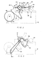
- FIG. 24 of the drawings there is shown diagrammatically in side elevation an in line installation generally indicated by reference numeral 240. It comprises generally an extruder 242 extruding synthetic plastic film in tubular form 244 drawn off by rollers 246. If desired, the film web 22 may pass through slitting and deblocking equipment 248 then through printing equipment 250 before it finally enters the side seal bag making machine 10 as already described. It will be noted from Figure 24 of the drawings, that the web 22 wraps around the sealing drum 14, to an extent of about 270°. This ensures that there is good contact between the drum and the web 22, and that the web spans the slots 16 of . the drum tightly, thereby resulting in good and effective welding of the web taking place along the edges of the perforations forming the zones of weakness. The drum 14 and its associated rollers will be driven in synchronism with the upstream printing installation and the extruder.
- roller 38 co-acts with the roller 36 and functions as draw-off rollers driven to have peripheral speeds at most one percent faster than the linear speed of the web 22.
- roller 40 may be driven independently of roller 38 to have a peripheral speed of up to two-fifths faster than the linear speed of the web 22.
- the circumferential lap of the web 22 around the sealing drum upstream of the sealing rotor is about 90°. This is to keep the roller 17 away from the sealing rotor so as to prevent overheating of the roller 17. Downstream of the sealing rotor, the circumferential lap of the web around the sealing drum is preferably in excess of 90 0 , up to about 180°. This is to ensure that the seals will have sufficient time to cool and for the welds to set, before the web leaves the sealing drum 14.
- bags made in accordance with the invention can be utilized in roll form, adjacent bags being held together by the holding lands 160.2. Bags can easily be torn from the roll, separation between adjacent bags taking place along the zones of weakness 160.
- the film used is conveniently low density polyethylene film.
- the bags are easily opened by having one lip 26.22 longer than the other lip 26.21.
- Film having a thickness of between 4 microns and 100 microns can be processed in accordance with the invention.
- low density polyethylene film, film of other materials can also be processed in the manner according to the invention.
- polypropylene film, high density polyethylene film, rigid polyvinylchloride film, ie without plasticiser, can all be processed in the manner as described.
- the linear speed of film from an extruder is much greater when extruding thin film than when extruding thick film. Accordingly, the bag-making machine according to the invention, with its capacity of high production rate of bags from thin film, makes possible its arrangement in line with and downstream from an extruder.
- the machine 10 can be usefully used in line with an extruder extruding thin film.
- the rate at which the web 22 passes through the machine 10 may then be accurately adjusted to match the extrusion rate of the extruder when it is producing thin film of the desired quality at its optimum rate.
- Such an installation is particularly well adapted to process film having a thickness in the range 4 to 30 microns.
Landscapes
- Making Paper Articles (AREA)
- Lining Or Joining Of Plastics Or The Like (AREA)
Applications Claiming Priority (2)
| Application Number | Priority Date | Filing Date | Title |
|---|---|---|---|
| ZA815383 | 1981-08-05 | ||
| ZA815383 | 1981-08-05 |
Publications (2)
| Publication Number | Publication Date |
|---|---|
| EP0072086A2 true EP0072086A2 (fr) | 1983-02-16 |
| EP0072086A3 EP0072086A3 (fr) | 1983-07-20 |
Family
ID=25575565
Family Applications (1)
| Application Number | Title | Priority Date | Filing Date |
|---|---|---|---|
| EP82301978A Withdrawn EP0072086A3 (fr) | 1981-08-05 | 1982-04-16 | Méthode et appareil pour la fabrication de sacs à partir d'une matière plastique synthétique |
Country Status (3)
| Country | Link |
|---|---|
| EP (1) | EP0072086A3 (fr) |
| JP (1) | JPS5865646A (fr) |
| AU (1) | AU549571B2 (fr) |
Cited By (2)
| Publication number | Priority date | Publication date | Assignee | Title |
|---|---|---|---|---|
| US8904740B2 (en) | 2012-08-21 | 2014-12-09 | Intertape Polymer Corp. | Method and apparatus for changing a strip of sealed bag precursors in to open bags |
| US9139317B2 (en) | 2012-08-21 | 2015-09-22 | Intertape Polymer Corp. | Method and apparatus for opening bags while maintaining a continuous strip of bag precursors |
Family Cites Families (6)
| Publication number | Priority date | Publication date | Assignee | Title |
|---|---|---|---|---|
| GB1257937A (fr) * | 1969-07-07 | 1971-12-22 | ||
| US3725180A (en) * | 1969-11-06 | 1973-04-03 | H Membrino | Bag-making machine for thermoplastic bags |
| DE2000551C3 (de) * | 1970-01-07 | 1974-08-15 | Hercules Philadelphia Pa. Membrino (V.St.A.) | Maschine zum Herstellen von Säcken aus Kunststoffolie |
| AT333496B (de) * | 1971-07-23 | 1976-11-25 | Showa Denko Kk | Vorrichtung zum biaxialen verstrecken von schlauchfolien aus kunststoff |
| AT334076B (de) * | 1973-06-05 | 1976-12-27 | Pannenbecker H | Verfahren zum herstellen von kunststoffolien |
| JPS5322911B2 (fr) * | 1973-08-23 | 1978-07-11 |
-
1982
- 1982-04-16 EP EP82301978A patent/EP0072086A3/fr not_active Withdrawn
- 1982-04-27 AU AU83050/82A patent/AU549571B2/en not_active Ceased
- 1982-07-23 JP JP57129509A patent/JPS5865646A/ja active Pending
Cited By (4)
| Publication number | Priority date | Publication date | Assignee | Title |
|---|---|---|---|---|
| US8904740B2 (en) | 2012-08-21 | 2014-12-09 | Intertape Polymer Corp. | Method and apparatus for changing a strip of sealed bag precursors in to open bags |
| WO2014031364A3 (fr) * | 2012-08-21 | 2015-07-16 | Gess Larry C | Procédé et appareil de changement d'une bande de précurseurs de sacs scellés en sacs ouverts |
| US9139317B2 (en) | 2012-08-21 | 2015-09-22 | Intertape Polymer Corp. | Method and apparatus for opening bags while maintaining a continuous strip of bag precursors |
| US9352525B2 (en) | 2012-08-21 | 2016-05-31 | Intertape Polymer Corp. | Method and apparatus for changing a strip of sealed bag precursors in to open bags |
Also Published As
| Publication number | Publication date |
|---|---|
| EP0072086A3 (fr) | 1983-07-20 |
| JPS5865646A (ja) | 1983-04-19 |
| AU549571B2 (en) | 1986-01-30 |
| AU8305082A (en) | 1983-02-10 |
Similar Documents
| Publication | Publication Date | Title |
|---|---|---|
| US4642084A (en) | Plastic bag making machine | |
| US3257256A (en) | Device for welding and cutting thermoplastic webs | |
| US6120634A (en) | Method and apparatus for forming agricultural drip tape | |
| US4262473A (en) | Method and apparatus for manufacturing tea bags and the like | |
| US5768852A (en) | Vertical form, fill and seal machine, components and method for making reclosable bags | |
| US4436568A (en) | In situ precipitated fibrous laminate and method of producing same | |
| US4023470A (en) | Method and apparatus for continuous production of bags from thermoplastic film | |
| US5112632A (en) | Method and apparatus for forming and hermetically sealing slices of food items | |
| US4333790A (en) | Rotary bag sealing and perforating machine | |
| US3622421A (en) | Method for forming bags from thermoplastic tubing | |
| US4567984A (en) | Plastic bag package | |
| US9352525B2 (en) | Method and apparatus for changing a strip of sealed bag precursors in to open bags | |
| PL91109B1 (fr) | ||
| US3947198A (en) | Apparatus for making bags from synthetic plastic film | |
| EP0072086A2 (fr) | Méthode et appareil pour la fabrication de sacs à partir d'une matière plastique synthétique | |
| EP0038559A2 (fr) | Procédé pour la fabrication d'une feuille résistant à l'abrasion et appareil pour sa fabrication | |
| GB1578567A (en) | Method and apparatus for perforating synthetic plastics film | |
| US5069659A (en) | Apparatus for the production of shopping bags having reinforced handle holes | |
| US3950205A (en) | Rotary heat sealer | |
| JP3370958B2 (ja) | 紙おしぼり製造装置、紙おしぼり包装装置およびこれらを組み合わせた紙おしぼり製品製造設備とその製造方法 | |
| US3018882A (en) | Spiral roll of perforated thermoplastic multiple tubing and method and apparatus for producing same | |
| EP0377416B1 (fr) | Installation pour la fabrication en continu de sacs en utilisant du polypropylène, polythène, PVC ou matériaux plastiques similaires | |
| EP0942824B1 (fr) | Procede et dispositif servant a obtenir des sections individuelles de bande a partir d'une bande de materiau | |
| US3506523A (en) | Machine for forming bags from thermoplastic tubing | |
| US3767508A (en) | Rotary heat sealer |
Legal Events
| Date | Code | Title | Description |
|---|---|---|---|
| PUAI | Public reference made under article 153(3) epc to a published international application that has entered the european phase |
Free format text: ORIGINAL CODE: 0009012 |
|
| AK | Designated contracting states |
Designated state(s): AT BE CH DE FR GB IT LI LU NL SE |
|
| PUAL | Search report despatched |
Free format text: ORIGINAL CODE: 0009013 |
|
| AK | Designated contracting states |
Designated state(s): AT BE CH DE FR GB IT LI LU NL SE |
|
| STAA | Information on the status of an ep patent application or granted ep patent |
Free format text: STATUS: THE APPLICATION IS DEEMED TO BE WITHDRAWN |
|
| 18D | Application deemed to be withdrawn |
Effective date: 19840321 |