EP0072154A2 - Circuits d'impulsion pour générer des impulsions de très haute tension - Google Patents
Circuits d'impulsion pour générer des impulsions de très haute tension Download PDFInfo
- Publication number
- EP0072154A2 EP0072154A2 EP82304010A EP82304010A EP0072154A2 EP 0072154 A2 EP0072154 A2 EP 0072154A2 EP 82304010 A EP82304010 A EP 82304010A EP 82304010 A EP82304010 A EP 82304010A EP 0072154 A2 EP0072154 A2 EP 0072154A2
- Authority
- EP
- European Patent Office
- Prior art keywords
- pulse
- transformer
- bias
- circuit
- high voltage
- Prior art date
- Legal status (The legal status is an assumption and is not a legal conclusion. Google has not performed a legal analysis and makes no representation as to the accuracy of the status listed.)
- Ceased
Links
Images

Classifications
-
- G—PHYSICS
- G01—MEASURING; TESTING
- G01S—RADIO DIRECTION-FINDING; RADIO NAVIGATION; DETERMINING DISTANCE OR VELOCITY BY USE OF RADIO WAVES; LOCATING OR PRESENCE-DETECTING BY USE OF THE REFLECTION OR RERADIATION OF RADIO WAVES; ANALOGOUS ARRANGEMENTS USING OTHER WAVES
- G01S7/00—Details of systems according to groups G01S13/00, G01S15/00, G01S17/00
- G01S7/02—Details of systems according to groups G01S13/00, G01S15/00, G01S17/00 of systems according to group G01S13/00
- G01S7/28—Details of pulse systems
- G01S7/282—Transmitters
-
- H—ELECTRICITY
- H03—ELECTRONIC CIRCUITRY
- H03K—PULSE TECHNIQUE
- H03K5/00—Manipulating of pulses not covered by one of the other main groups of this subclass
- H03K5/01—Shaping pulses
- H03K5/04—Shaping pulses by increasing duration; by decreasing duration
Definitions
- a pulse circuit includes a pulse transformer arranged to receive a low voltage high current pulse from a pulse generator and to transform it into a high voltage pulse for utilisation by a load, the duration of the high voltage pulse being determined by the time taken for the reactor of the pulse transformer to saturate; and means for biassing the magnetic flux state of the pulse transformer to a selectable level prior to the reception of the low voltage pulses whereby the duration of the high voltage pulses produced by the transformer is reduced from a predetermined maximum value by an amount related to the selectable bias level.
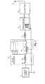
- the magnetron 4 is such as to oscillate at microwave frequencies whenever a sufficiently high voltage is applied to it, and the shape of the transmitted pulses and the ceficiency with which they are transmitted is primarily dependent on the nature of the pulses generated at the pulse generator 2 and the way in which they are transformed from a low voltage to a high voltage by the transformer 3.
- the above arrangement works very well when the radar system is to transmit pulses having only one duration determined primarily by the characteristics of the pulse forming network and the pulse transformer, but often it is desired to transmit pulses of various different lengths. For example, for long range work it is desired to maximise the transmitted power, and under such circumstances relatively long radar pulses are transmitted. However, the detection of targets at very close range requires the transmission of very short pulses so that the pulse terminates by the time that echoes of it begin to be received. It is extremely difficult and unsatisfactory to switchably select different transformers in dependence on the required pulse length, but switchably, or electrically, programmable pulse forming networks are relatively straight forward.
- FIG. 2 shows the magnetic characteristics of the pulse transformer 3. It has a very square B-H hysteresis loop (the value of remanent to maximum flux density is preferably between 0.9 and 11. Prior to the application of a pulse from the pulse generator 2, the magnetic flux state of the transformer is re-set to point 20. Then when the pulse is applied to the primary winding of the transformer 3, the magneting force associated with the pulse causes the flux state to shift along curve 21 and it is arranged that the longest required pulse terminates at the time that point 22 is reached.
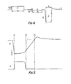
- FIG. 5 is used to further explain the operation of the circuit shown in Figure 3 and to explain the problem which the present invention overcomes.
- Line a shows the magnitude of the voltage which would be present on a magnetron if a relatively short pulse were applied to the pulse transformer 3 so that the pulse terminated before the magnetic material of the transformer had saturated.
- the current pulse generated by the pulse generator 2 commences at time tl and ceases at time t 2 , but at time t 2 the capacitance of the magnetron 4 remains charged and decays only slowly to reach zero at time t 3 .
- the magnetron is liable to emit random oscillations and unwanted noise which could seriously interfere with the reception of a weak echo from a radar target.
Landscapes
- Physics & Mathematics (AREA)
- Engineering & Computer Science (AREA)
- Nonlinear Science (AREA)
- Computer Networks & Wireless Communication (AREA)
- General Physics & Mathematics (AREA)
- Radar, Positioning & Navigation (AREA)
- Remote Sensing (AREA)
- Radar Systems Or Details Thereof (AREA)
Applications Claiming Priority (2)
| Application Number | Priority Date | Filing Date | Title |
|---|---|---|---|
| GB08124321A GB2105121B (en) | 1981-08-08 | 1981-08-08 | Pulse circuits |
| GB8124321 | 1981-08-08 |
Publications (2)
| Publication Number | Publication Date |
|---|---|
| EP0072154A2 true EP0072154A2 (fr) | 1983-02-16 |
| EP0072154A3 EP0072154A3 (fr) | 1983-10-12 |
Family
ID=10523819
Family Applications (1)
| Application Number | Title | Priority Date | Filing Date |
|---|---|---|---|
| EP82304010A Ceased EP0072154A3 (fr) | 1981-08-08 | 1982-07-29 | Circuits d'impulsion pour générer des impulsions de très haute tension |
Country Status (2)
| Country | Link |
|---|---|
| EP (1) | EP0072154A3 (fr) |
| GB (1) | GB2105121B (fr) |
Cited By (2)
| Publication number | Priority date | Publication date | Assignee | Title |
|---|---|---|---|---|
| DE19906233B4 (de) * | 1998-06-05 | 2006-05-04 | Mitsubishi Denki K.K. | Auf einem Fahrzeug angebrachte Radareinrichtung |
| CN102394609A (zh) * | 2011-10-25 | 2012-03-28 | 中国兵器工业集团第二一四研究所苏州研发中心 | 一种窄脉冲电压放大器 |
Family Cites Families (4)
| Publication number | Priority date | Publication date | Assignee | Title |
|---|---|---|---|---|
| US2579542A (en) * | 1945-09-18 | 1951-12-25 | Winston H Bostick | Pulse transformer circuit |
| US2652502A (en) * | 1951-09-05 | 1953-09-15 | British Thomson Houston Co Ltd | Pulse generating circuit |
| DE1108265B (de) * | 1957-08-02 | 1961-06-08 | Csf | Impulsuebertrager mit Impulsbreitenregelung |
| US3928809A (en) * | 1974-05-06 | 1975-12-23 | Whittaker Corp | Pulse width control system |
-
1981
- 1981-08-08 GB GB08124321A patent/GB2105121B/en not_active Expired
-
1982
- 1982-07-29 EP EP82304010A patent/EP0072154A3/fr not_active Ceased
Cited By (3)
| Publication number | Priority date | Publication date | Assignee | Title |
|---|---|---|---|---|
| DE19906233B4 (de) * | 1998-06-05 | 2006-05-04 | Mitsubishi Denki K.K. | Auf einem Fahrzeug angebrachte Radareinrichtung |
| CN102394609A (zh) * | 2011-10-25 | 2012-03-28 | 中国兵器工业集团第二一四研究所苏州研发中心 | 一种窄脉冲电压放大器 |
| CN102394609B (zh) * | 2011-10-25 | 2014-06-18 | 中国兵器工业集团第二一四研究所苏州研发中心 | 一种窄脉冲电压放大器 |
Also Published As
| Publication number | Publication date |
|---|---|
| GB2105121A (en) | 1983-03-16 |
| GB2105121B (en) | 1985-01-23 |
| EP0072154A3 (fr) | 1983-10-12 |
Similar Documents
| Publication | Publication Date | Title |
|---|---|---|
| US4767999A (en) | Method of and apparatus for radio-frequency generation in resonator tank circuits excited by sequential pulses of alternately opposite polarity | |
| US3711725A (en) | Apparatus and method for radio-frequency pulse generation in tuned radio-frequency loads | |
| GB2104326A (en) | A pulse generator | |
| IL45757A (en) | Radio-frequency pulse generation system and method | |
| US4160214A (en) | Modular modulator for radar transmitters | |
| US3296551A (en) | Solid state modulator circuit for selectively providing different pulse widths | |
| US3171040A (en) | Fast charging circuit for pulse networks | |
| US3928809A (en) | Pulse width control system | |
| US6914556B1 (en) | Method and apparatus for magnetron coherence | |
| CA1273412A (fr) | Modulateur d'impulsion | |
| GB2135547A (en) | Pulse circuits | |
| GB2105121A (en) | Pulse circuits | |
| US3881120A (en) | Pulse generating circuit | |
| US3486043A (en) | High power pulse width modulator employing step recovery diodes | |
| US3424925A (en) | Scr pulse forming and shaping network | |
| US2946958A (en) | Modulators | |
| US3385982A (en) | High power solid state pulse generator with very short rise time | |
| US5969439A (en) | Pulse generator apparatus for RF pulse generation in tuned loads including series regulation and capacitor clamping method therefor | |
| US3705418A (en) | Digital pulse signal transmission circuit | |
| US4051439A (en) | Short pulse magnetron transmitter | |
| US2436395A (en) | Pulse generator | |
| US3292006A (en) | Storage diode pulse signal generator | |
| US3058011A (en) | Generator of random double pulse pairs | |
| US3144567A (en) | Pulse generators | |
| US2904684A (en) | Frequency-stabilized pulse generator |
Legal Events
| Date | Code | Title | Description |
|---|---|---|---|
| PUAI | Public reference made under article 153(3) epc to a published international application that has entered the european phase |
Free format text: ORIGINAL CODE: 0009012 |
|
| AK | Designated contracting states |
Designated state(s): AT BE CH DE FR IT LI LU NL SE |
|
| PUAL | Search report despatched |
Free format text: ORIGINAL CODE: 0009013 |
|
| AK | Designated contracting states |
Designated state(s): AT BE CH DE FR IT LI LU NL SE |
|
| 17P | Request for examination filed |
Effective date: 19831221 |
|
| STAA | Information on the status of an ep patent application or granted ep patent |
Free format text: STATUS: THE APPLICATION HAS BEEN REFUSED |
|
| 18R | Application refused |
Effective date: 19860506 |
|
| RIN1 | Information on inventor provided before grant (corrected) |
Inventor name: RICHARDSON, ROBERT |