EP0072194A1 - Endoskope - Google Patents
Endoskope Download PDFInfo
- Publication number
- EP0072194A1 EP0072194A1 EP82304106A EP82304106A EP0072194A1 EP 0072194 A1 EP0072194 A1 EP 0072194A1 EP 82304106 A EP82304106 A EP 82304106A EP 82304106 A EP82304106 A EP 82304106A EP 0072194 A1 EP0072194 A1 EP 0072194A1
- Authority
- EP
- European Patent Office
- Prior art keywords
- light guide
- grip portion
- connector
- opening
- pressed
- Prior art date
- Legal status (The legal status is an assumption and is not a legal conclusion. Google has not performed a legal analysis and makes no representation as to the accuracy of the status listed.)
- Ceased
Links
Images

Classifications
-
- A—HUMAN NECESSITIES
- A61—MEDICAL OR VETERINARY SCIENCE; HYGIENE
- A61B—DIAGNOSIS; SURGERY; IDENTIFICATION
- A61B1/00—Instruments for performing medical examinations of the interior of cavities or tubes of the body by visual or photographical inspection, e.g. endoscopes; Illuminating arrangements therefor
- A61B1/06—Instruments for performing medical examinations of the interior of cavities or tubes of the body by visual or photographical inspection, e.g. endoscopes; Illuminating arrangements therefor with illuminating arrangements
- A61B1/07—Instruments for performing medical examinations of the interior of cavities or tubes of the body by visual or photographical inspection, e.g. endoscopes; Illuminating arrangements therefor with illuminating arrangements using light-conductive means, e.g. optical fibres
-
- A—HUMAN NECESSITIES
- A61—MEDICAL OR VETERINARY SCIENCE; HYGIENE
- A61B—DIAGNOSIS; SURGERY; IDENTIFICATION
- A61B1/00—Instruments for performing medical examinations of the interior of cavities or tubes of the body by visual or photographical inspection, e.g. endoscopes; Illuminating arrangements therefor
- A61B1/00112—Connection or coupling means
- A61B1/00121—Connectors, fasteners and adapters, e.g. on the endoscope handle
- A61B1/00126—Connectors, fasteners and adapters, e.g. on the endoscope handle optical, e.g. for light supply cables
-
- A—HUMAN NECESSITIES
- A61—MEDICAL OR VETERINARY SCIENCE; HYGIENE
- A61B—DIAGNOSIS; SURGERY; IDENTIFICATION
- A61B1/00—Instruments for performing medical examinations of the interior of cavities or tubes of the body by visual or photographical inspection, e.g. endoscopes; Illuminating arrangements therefor
- A61B1/00112—Connection or coupling means
- A61B1/00121—Connectors, fasteners and adapters, e.g. on the endoscope handle
- A61B1/00128—Connectors, fasteners and adapters, e.g. on the endoscope handle mechanical, e.g. for tubes or pipes
Definitions
- This invention relates to endoscopes of the type wherein a rigid insertion sheath is provided at its rear, operating grip portion with light guide connector to which a light guide cable can be removably fitted.
- an illuminating light from an external light source needs to be led via the light guide cable, to be transmitted on through the entrance end surfaces of light guide fibres at the light guide connector to which the light guide cable can be removably fitted, and so transmitted to the tip of the insertion sheath from the operating grip portion via the light guide fibres within the sheath, and will be projected from the tip to illuminate the affected part.
- the light guide connector is fitted to the operating grip portion by screwing, bonding or brazing.
- Fitting by bonding also presents problems, as it is difficult to positively fix the light guide mouthpiece to the operating grip portion with adequate strength and, in bonding, there have been problems that such pretreatment as degreasing must be effectively carried out.
- Fitting by brazing or the like presents problems due to the temperature required in the case of brazing, as the bonding agent used to form the light guide fibres into a bunch may be scorched and lose its function as a bonding agent, and in any case the scorched portion will absorb illuminating light, and reduce efficiency so that the light will not be well transmitted.
- the present invention relates to a hard endoscope wherein a light guide cable transmitting an illuminating light of an external light source is connected at the end with light guide fibres as illuminating light transmitting means through a light guide mouthpiece, characterised in that an opening is formed on the side of an operating part and a pressed-in part which can be pressed and fixed in the above mentioned opening is formed on the base side of the light guide mouthpiece.
- One object of the present invention is to provide an endoscope wherein a light guide connector can be fitted to an operating grip portion by a simple structure, avoiding the above-mentioned problems at a low cost, whilst ensuring that the connector can be fitted to an operating grip portion without a risk of breaking light guide fibres.
- an endoscope of the type wherein a rigid insertiot sheath contains light guide fibres extending from its tip to a connector on an operating grip portion, said connector being coupled, when in use, to a light guide cable leading an external illuminating light source, characterised in that an opening is formed on the side of the operating grip portion the base end of the light guide connector is formed as a pressed-in part so as to be force-fitted into said opening to fix the light guide connector to the operating grip portion.
- the endoscope comprises an insertion sheath 1 to be inserted into a body cavity, an operating grip portion 2 for operation, and an eyepiece 3 for observation.
- a light guide connector 4 is provided on the grip portion 2 to connect a light guide cable (not shown) connected to an external light source (not shown).
- a male screw thread 5 is cut in the connecting part of the light guide connector 4, and a female screw thread 6 is cut in the wall of a hole in the operating grip portion 2, and these screw threads 5 and 6 are screwed together to secure the light guide connector 4 to the operating grip portion 2.
- a light guide fibre bunch 7 is inserted to extend from the above-mentioned light guide connector 4 to the tip of the insertion sheath 1.
- a light guide cable leading an illuminating light of an external light source (not illustrated) is removably fitted to the connector by a click-stop groove on the above-mentioned light guide connector 4 so that the illuminating light may be transmitted on to be projected at the tip of the insertion sheath.
- the working steps are increased, the light guide fibre bunch 7 may be twisted and broken as the light guide connector 4 is screwed in, and in cases where a stainless steel is used for the light guide connector 4 to increase resistance to corrosion, it will be difficult to cut screw threads, the tool (blade) will be worn excessively and the space for the light guide fibres will be decreased by the need to provide for the screw thread in the connector wall.
- the present invention is intended to avoid the problems of the above-mentioned conventional example and of the above described prior art.
- FIGS 3 and 4 show a first exemplary embodiment of the present invention.
- a rigid insertion sheath 11 of an endoscope is mounted on an operating grip portion 12 that has an eyepiece 13 at its rear end, and a light guide connector 14 containing a bunch of light guide fibres 15.
- the insertion sheath 11 of the endoscope is fitted to the operating grip portion 12 and the eyepiece 13 is screwed to this same part 12.
- the light guide connector 14 holding the light guide fibres 15 and forming a light entry port to the endoscope is connected at the outer periphery of the operating grip portion 12.
- an opening 12a is provided in the operating grip portion 12 and a pressed-in part 14a to be force-fitted into opening 12a is provided at the base of the light guide connector 14.
- a flat butting surface 12b is formed as a contact and engagement surface below an enlarged diameter entry portion 12c in the opening 12a of the operating grip portion 12.
- Both the pressed-in part 14a and a butting part 14b of a flange 14c at the rear of the pressed-in part 14a firmly and precisely engage, locate and secure the connector 14 when fitted to the operating grip portion 12.
- the caliber difference (so-called interference) between the internal diameter of the opening 12a and the external diameter of the pressed-in part 14a is about 10 to 20 J u,m.
- the pressed-in part 14a can be firmly pressed into the opening 12a, the light guide connector 14 then being securely fitted to the operating grip portion 12, and the butting parts 12b and 14b being brought into close contact with each other ensures that the position of the light guide connector 14 is correct in the vertical direction (the direction normal to the respective point on to the outer surface of the operating grip portion 12) and shields any clearance between the operating grip portion 12 and light guide connector 14 at the covering parts 12c and 14c.
- a taper 16 may be made by chamfering the peripheral edge of the extreme tip of the pressed-in part 14a of the light guide connector 14 to facilitate fitting the pressed--in part 14a into the opening 12a.
- An inner tube 17 provided in the sheath 11 contains an optical system,. which is not shown in detail.
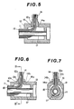
- Figure 5 shows the second exemplary embodiment of the present invention, in which the butting parts 12b and 14b for determining the position in the vertical direction in the first embodiment are omitted, and the light guide connector 14 is fitted in the operating grip portion 12 so that the opening 12a is only engaged by the pressed-in part 14a.
- the position in the direction normal to the outer surface of the operating grip portion 12 is determined by use of a positioning jig, so that the outer wall surfaces 12c and 14c are not required.
- the caliber difference between the inside diameter of the opening 12a and the outside diameter of the pressed-in part 14a can be about 10 to 20 ⁇ m, as the pressed-in part 14a is securely fitted by this caliber difference because of the greater length of mutual engagement, compared with the first embodiment.
- Figures 6 and 7 show the third embodiment of the present invention, in which the outer surface of the operating grip portion 12 is approximately square, and is provided with a square opening 12a.
- An elevated part 12d defining a flat outer peripheral surface is provided on the operating grip portion in the embodiment shown in Figure 6, and has the opening 12a formed in it.
- the pressed-in part 14a of the light guide connector 14 is force-fitted into the opening 12a until a butting part 14b at the front end of a flange formed on the light guide connector 14 is brought into close contact with the butting part 12b at the outer peripheral end of the opening 12a, so that the light guide connector 14 is positioned and held in the vertical direction. Even in this fitting form, the pressed-in part 14a is pressed and fitted in the opening 12a on the basis of the same caliber difference as the above- described embodiments.
- the pressed-in part 14a of the light guide connector 14 is pressed into close contact with a predetermined part of the opening 12a of the operating grip portion 12 so as to fit and fix the light guide connector 14 to the operating grip portion 12.
- the light guide mouthpiece 14 is pressed into the opening 12a formed in the operating part 12 until the butting part 14b of the light guide mouthpiece 14 contacts the butting part 12b on the flat end surface at the outer periphery of the opening 12a of the elevated part 12d, so as to be positioned and fixed in the vertical direction.
- butting surfaces 12b and 14b may be formed internally in the side wall of the opening 12a (in such case, the outer covering parts 12c and 14c will also be formed). Further, it is needless to say that, whatever the overall shape of the elevated part 12d, only that part immediately surrounding the opening 12a need be shaped to be flat.
- the position of the light guide mouthpiece 14 in the vertical direction can be determined by using a jig, during pressing and fixing, as described with reference to the second embodiment, and butting parts, 12b and 14b, together with associated covering parts 12c and 14c can then be omitted.
- the cross-sections of the opening 12a, pressed-in part 14a, and any flange part provided with a butting surface 14b must obviously be matched, but may be circular, or square, or of any other shape required to meet a particular problem.
Landscapes
- Health & Medical Sciences (AREA)
- Life Sciences & Earth Sciences (AREA)
- Surgery (AREA)
- Engineering & Computer Science (AREA)
- Biomedical Technology (AREA)
- Heart & Thoracic Surgery (AREA)
- Pathology (AREA)
- Radiology & Medical Imaging (AREA)
- Nuclear Medicine, Radiotherapy & Molecular Imaging (AREA)
- Biophysics (AREA)
- Physics & Mathematics (AREA)
- Optics & Photonics (AREA)
- Medical Informatics (AREA)
- Molecular Biology (AREA)
- Animal Behavior & Ethology (AREA)
- General Health & Medical Sciences (AREA)
- Public Health (AREA)
- Veterinary Medicine (AREA)
- Mechanical Engineering (AREA)
- Endoscopes (AREA)
Applications Claiming Priority (2)
| Application Number | Priority Date | Filing Date | Title |
|---|---|---|---|
| JP117199/81U | 1981-08-05 | ||
| JP11719981U JPS5822102U (ja) | 1981-08-05 | 1981-08-05 | 硬性内視鏡 |
Publications (1)
| Publication Number | Publication Date |
|---|---|
| EP0072194A1 true EP0072194A1 (de) | 1983-02-16 |
Family
ID=14705841
Family Applications (1)
| Application Number | Title | Priority Date | Filing Date |
|---|---|---|---|
| EP82304106A Ceased EP0072194A1 (de) | 1981-08-05 | 1982-08-04 | Endoskope |
Country Status (2)
| Country | Link |
|---|---|
| EP (1) | EP0072194A1 (de) |
| JP (1) | JPS5822102U (de) |
Cited By (2)
| Publication number | Priority date | Publication date | Assignee | Title |
|---|---|---|---|---|
| WO2005077254A3 (de) * | 2004-02-16 | 2006-01-19 | Storz Karl Gmbh & Co Kg | Verfahren zum fixieren von glasfasern in einem endoskop |
| FR2923026A1 (fr) * | 2007-10-31 | 2009-05-01 | Tokendo Soc Par Actions Simpli | Dispositif d'eclairage pour videoendoscope |
Citations (3)
| Publication number | Priority date | Publication date | Assignee | Title |
|---|---|---|---|---|
| GB1365723A (en) * | 1970-09-21 | 1974-09-04 | Cavis Cavetti Isolati Spa | Metal cable terminal for light guiding cable |
| GB1463350A (en) * | 1974-12-05 | 1977-02-02 | Bowthorpe Hellermann Ltd | Light guide contact |
| US4014098A (en) * | 1973-05-16 | 1977-03-29 | Vicon Products Corporation | Fiber optics element and dental handpiece containing the same |
-
1981
- 1981-08-05 JP JP11719981U patent/JPS5822102U/ja active Pending
-
1982
- 1982-08-04 EP EP82304106A patent/EP0072194A1/de not_active Ceased
Patent Citations (3)
| Publication number | Priority date | Publication date | Assignee | Title |
|---|---|---|---|---|
| GB1365723A (en) * | 1970-09-21 | 1974-09-04 | Cavis Cavetti Isolati Spa | Metal cable terminal for light guiding cable |
| US4014098A (en) * | 1973-05-16 | 1977-03-29 | Vicon Products Corporation | Fiber optics element and dental handpiece containing the same |
| GB1463350A (en) * | 1974-12-05 | 1977-02-02 | Bowthorpe Hellermann Ltd | Light guide contact |
Cited By (3)
| Publication number | Priority date | Publication date | Assignee | Title |
|---|---|---|---|---|
| WO2005077254A3 (de) * | 2004-02-16 | 2006-01-19 | Storz Karl Gmbh & Co Kg | Verfahren zum fixieren von glasfasern in einem endoskop |
| US8002699B2 (en) | 2004-02-16 | 2011-08-23 | Karl Storz Gmbh & Co. Kg | Endoscope and method for fixing optical fibers therein |
| FR2923026A1 (fr) * | 2007-10-31 | 2009-05-01 | Tokendo Soc Par Actions Simpli | Dispositif d'eclairage pour videoendoscope |
Also Published As
| Publication number | Publication date |
|---|---|
| JPS5822102U (ja) | 1983-02-10 |
Similar Documents
| Publication | Publication Date | Title |
|---|---|---|
| EP0070652B1 (de) | Starres Endoskop | |
| US5261391A (en) | Threaded flexible guide tube for endoscope | |
| US4971035A (en) | Insert part of endoscope | |
| US4615333A (en) | Rigid endoscope of oblique window type | |
| EP0093599B1 (de) | Nicht beugsames Endoskop mit schiefwinkliger Sichtrichtung | |
| US4416268A (en) | Endoscope having two detachable armour tubes | |
| CA2565820C (en) | Endoscope and related system | |
| EP0216138A2 (de) | Endoskop | |
| US20050256377A1 (en) | Endoscope and related system | |
| EP1774895B1 (de) | Endoskop und verfahren zur reparatur eines endoskops | |
| CN219270851U (zh) | 前端头组件和内窥镜 | |
| DE4303756A1 (en) | Clinical monitoring instrument incorporating optical fibre bundle - illuminates interior or organ by repetitive total internal reflection between both walls of hollow circular transparent cone | |
| EP0072205B1 (de) | Anschlussstück für Endoskopdeckglas | |
| US5013122A (en) | Threaded crimping body for fiber optic termination | |
| US10254489B2 (en) | Connector for optic fiber cable and crimping tool for optic fiber cable | |
| EP0072193B1 (de) | Endoskope | |
| JPS6348241Y2 (de) | ||
| JPH0687094B2 (ja) | 内視鏡先端アダプタ装置 | |
| JPH0440011B2 (de) | ||
| JP3668297B2 (ja) | 内視鏡の先端部 | |
| JPH0328815A (ja) | 工業用内視鏡 | |
| JPS6343446Y2 (de) | ||
| JP3653908B2 (ja) | 内視鏡の処置具挿通チャンネル | |
| JPH0519044Y2 (de) | ||
| JPH0142086Y2 (de) |
Legal Events
| Date | Code | Title | Description |
|---|---|---|---|
| PUAI | Public reference made under article 153(3) epc to a published international application that has entered the european phase |
Free format text: ORIGINAL CODE: 0009012 |
|
| AK | Designated contracting states |
Designated state(s): AT BE CH DE FR GB IT LI NL SE |
|
| 17P | Request for examination filed |
Effective date: 19830124 |
|
| STAA | Information on the status of an ep patent application or granted ep patent |
Free format text: STATUS: THE APPLICATION HAS BEEN REFUSED |
|
| 18R | Application refused |
Effective date: 19850708 |
|
| RIN1 | Information on inventor provided before grant (corrected) |
Inventor name: HASHIGUCHI, TOSHIHIKO |