EP0072199A1 - Rohrkupplung - Google Patents
Rohrkupplung Download PDFInfo
- Publication number
- EP0072199A1 EP0072199A1 EP82304115A EP82304115A EP0072199A1 EP 0072199 A1 EP0072199 A1 EP 0072199A1 EP 82304115 A EP82304115 A EP 82304115A EP 82304115 A EP82304115 A EP 82304115A EP 0072199 A1 EP0072199 A1 EP 0072199A1
- Authority
- EP
- European Patent Office
- Prior art keywords
- pipe
- lock ring
- section
- protuberance
- pipe coupling
- Prior art date
- Legal status (The legal status is an assumption and is not a legal conclusion. Google has not performed a legal analysis and makes no representation as to the accuracy of the status listed.)
- Granted
Links
- 238000010168 coupling process Methods 0.000 title claims abstract description 32
- 238000005859 coupling reaction Methods 0.000 title claims abstract description 32
- 230000008878 coupling Effects 0.000 title claims abstract description 30
- 230000000452 restraining effect Effects 0.000 claims description 4
- 230000000149 penetrating effect Effects 0.000 claims description 2
- 230000002596 correlated effect Effects 0.000 claims 1
- 229920003023 plastic Polymers 0.000 abstract description 11
- 239000004033 plastic Substances 0.000 abstract description 11
- 239000002184 metal Substances 0.000 abstract description 5
- 230000000694 effects Effects 0.000 abstract description 4
- 238000009434 installation Methods 0.000 abstract 1
- 229910000831 Steel Inorganic materials 0.000 description 8
- 239000010959 steel Substances 0.000 description 8
- 238000010276 construction Methods 0.000 description 7
- 239000000203 mixture Substances 0.000 description 4
- 230000035515 penetration Effects 0.000 description 3
- 230000033228 biological regulation Effects 0.000 description 2
- 239000012530 fluid Substances 0.000 description 2
- 238000005242 forging Methods 0.000 description 2
- 238000007789 sealing Methods 0.000 description 2
- 238000010008 shearing Methods 0.000 description 2
- ZEFNOZRLAWVAQF-UHFFFAOYSA-N Dinitolmide Chemical compound CC1=C(C(N)=O)C=C([N+]([O-])=O)C=C1[N+]([O-])=O ZEFNOZRLAWVAQF-UHFFFAOYSA-N 0.000 description 1
- 230000006835 compression Effects 0.000 description 1
- 238000007906 compression Methods 0.000 description 1
- 238000005520 cutting process Methods 0.000 description 1
- 230000001419 dependent effect Effects 0.000 description 1
- 229920001971 elastomer Polymers 0.000 description 1
- 239000000806 elastomer Substances 0.000 description 1
- 239000004519 grease Substances 0.000 description 1
- 230000014759 maintenance of location Effects 0.000 description 1
- 238000004519 manufacturing process Methods 0.000 description 1
- 239000000463 material Substances 0.000 description 1
- 230000002265 prevention Effects 0.000 description 1
- 230000003313 weakening effect Effects 0.000 description 1
- 238000003466 welding Methods 0.000 description 1
Images
Classifications
-
- F—MECHANICAL ENGINEERING; LIGHTING; HEATING; WEAPONS; BLASTING
- F16—ENGINEERING ELEMENTS AND UNITS; GENERAL MEASURES FOR PRODUCING AND MAINTAINING EFFECTIVE FUNCTIONING OF MACHINES OR INSTALLATIONS; THERMAL INSULATION IN GENERAL
- F16L—PIPES; JOINTS OR FITTINGS FOR PIPES; SUPPORTS FOR PIPES, CABLES OR PROTECTIVE TUBING; MEANS FOR THERMAL INSULATION IN GENERAL
- F16L37/00—Couplings of the quick-acting type
- F16L37/02—Couplings of the quick-acting type in which the connection is maintained only by friction of the parts being joined
- F16L37/04—Couplings of the quick-acting type in which the connection is maintained only by friction of the parts being joined with an elastic outer part pressing against an inner part by reason of its elasticity
- F16L37/06—Couplings of the quick-acting type in which the connection is maintained only by friction of the parts being joined with an elastic outer part pressing against an inner part by reason of its elasticity tightened by fluid pressure
-
- F—MECHANICAL ENGINEERING; LIGHTING; HEATING; WEAPONS; BLASTING
- F16—ENGINEERING ELEMENTS AND UNITS; GENERAL MEASURES FOR PRODUCING AND MAINTAINING EFFECTIVE FUNCTIONING OF MACHINES OR INSTALLATIONS; THERMAL INSULATION IN GENERAL
- F16L—PIPES; JOINTS OR FITTINGS FOR PIPES; SUPPORTS FOR PIPES, CABLES OR PROTECTIVE TUBING; MEANS FOR THERMAL INSULATION IN GENERAL
- F16L17/00—Joints with packing adapted to sealing by fluid pressure
- F16L17/10—Joints with packing adapted to sealing by fluid pressure the packing being sealed by the pressure of a fluid other than the fluid in or surrounding the pipe
Definitions
- This invention relates to a pipe coupling comprising a radially deformable elongate shell in which to receive a pipe section to be coupled; at least one gasket recess defined interior of said shell in a deformable section thereof; and a gasket contained in said recess.
- a form of coupling particularly suited for underground gas piping is comprised of a cylindrical sleeve that is inwardly swaged in the course of compressing an annular gasket into sealing engagement about a contained pipe end.
- Such couplings are commercially available under the trademark POSI-HOLD and generally correspond to the structure disclosed in U.S. patents 3,429,587 and 3,915,480.
- Another form of swageable coupling likewise marketed under the same trademark is of a structure generally disclosed in Canadian patent No. 928,360.
- the present invention is characterised in that an inward protuberance is defined interior of said shell on a deformable section thereof axially displaced from said gasket recess and a lock ring having a toothed inner face is provided for positioned placement against the inner face of said protuberance, said lock ring being responsive to inward deformation of said protuberance to constrict radially inward into a penetrating gripping engagement with a contained pipe section to impose a restraining force on the pipe section tending to resist pullout of said pipe section.
- a metal lock ring of predetermined circumferential extent is constructed with a serrated gripping surface on its radially inner face formed as annular extending chisel shaped teeth.
- the outer periphery of the ring is centrally dished inwardly to receive the annular protuberance axially located in the internal diameter of the coupling.
- the protuberance serves both to position the lock ring, and in the course of swaging for effecting a coupled joint, to transmit the swage force to the lock ring for radially constraining the lock ring into a radial grip against the pipe wall thereat.
- one lock ring is universally suitable for gas pipe of different composition and the previous expense attributed to fabrication and inventory of separate rings for separate purposes in the manner of the prior art is eliminated.
- the imposed pullout restraint is more positive and more readily controllable in becoming effective immediately in the course of swaging, in contrast with the post-coupling effect resulting from an inclined plane in the manner of the prior art.
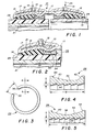
- FIGs. 1 and 2 of the drawings there is illustrated a deformable swage-type coupling similar to that disclosed in U.S. patent Nos. 3,429,587 and 3,915,480.
- the coupling is generally designated 10 and comprises an elognated tubular shell 11. Formed internally of the shell near each end thereof is a deformable annular arch 12 merging with a radially inward extending recess 13, and which together on their interior face define gasket recesses 14. Contained in the gasket recesses 14 are annular elastomeric gaskets 15 and 16.
- each end portion of shell 11 is an outer pressure ring 17 secured thereto as by welding or the like. Between the pressure ring and shell there is defined a pressure-tight annular passage 18 formed by the exterior spanned surface thereat of shell 11 and the interior surface of ring 17. Exposing passage 18 to the exterior of ring 17 is a port 19 through which passage 18 can be supplied with a non-compressible fluid under pressure, such as commercially available forms of oil or grease. A forging tool available for that purpose is disclosed in U. S. patent No. 3,505,845. Oppositely received within shell 11 are ends of pipe sections 23 and 24 to be coupled, one or the other or both of which can be of steel, plastic, etc.
- fluid pressure from a source 25 is introduced via thruport 19 such that when sufficient internal pressure is developed, shell 11 constricts radially inward.
- the forging or swaging is continued until the shell is forged beyond its yield point in compression as to effect a permanent deformation from the relationship of Fig. 1 to the relation shown in Fig. 2 for the latter to provide a firm leak-tight seal between compressed gasket 15 and pipe 23 thereat.
- a tubular sleeve 21 of metal or other inelastic material initially inserted in the pipe end prior to forming the coupled joint.
- a circumferentially extending lock ring 28 preferably of steel, having an initially controlled circumferential extent less than annular as to define a gap angle a between radial end faces 30 and 32.
- a plurality of wedge or chisel shaped teeth 34 comprising the gripping surface thereof.
- ring 28 is centrally dished or channeled at 36 in a manner to permit an interfitting placement and retention against inward protuberance 38 formed about the underside of recess 13.
- the fit of protuberance 38 within ring recess 36 is somewhat critical in that radial clearances therebetween should ensure that radial location of teeth 34 will result in an adequate grip with a contained pipe thereat.
- the chamfered sides 40 and 42 of recess 36 are intended to ensure an enhanced grip against contained pipe in the event any significant pullout force is encountered. Shoulder 44 in Fig.
- the maximum tooth depth "A” is largely governed by any weakening effect likely to be encountered from cutting through of the plastic pipe wall thickness.
- minimum tooth depth "A” is determined by the penetration necessary to retain plastic pipe without shearing the O.D. wall at the required tensile load, for a given ring width "W” with a given number of teeth. Increasing the number of teeth, at the same pitch by an increased width "W” of ring 28 enables some decrease in the necessary tooth depth.
- the number of teeth should be limited to prevent a lowering of pullout strength from a shallower tooth penetration resulting from the same collapsing load distributed over more teeth.
- a decrease in the number of teeth 34 can result in a lowering of pullout strength from the load being divided equally among fewer teeth.
- a preferred profile includes seven teeth 34 at about 3.175 mm pitch at a depth "A" of about 1.626 mm. This was found to withstand a tensile load exceeding 137.8 kN as compared to the D.O.T. standard requirement of 116.5 kN.
Landscapes
- Engineering & Computer Science (AREA)
- General Engineering & Computer Science (AREA)
- Physics & Mathematics (AREA)
- Fluid Mechanics (AREA)
- Mechanical Engineering (AREA)
- Joints With Sleeves (AREA)
- Quick-Acting Or Multi-Walled Pipe Joints (AREA)
- Gasket Seals (AREA)
- Non-Disconnectible Joints And Screw-Threaded Joints (AREA)
Applications Claiming Priority (2)
| Application Number | Priority Date | Filing Date | Title |
|---|---|---|---|
| US290038 | 1981-08-05 | ||
| US06/290,038 US4466640A (en) | 1981-08-05 | 1981-08-05 | Pullout resistant pipe coupling |
Publications (2)
| Publication Number | Publication Date |
|---|---|
| EP0072199A1 true EP0072199A1 (de) | 1983-02-16 |
| EP0072199B1 EP0072199B1 (de) | 1986-04-02 |
Family
ID=23114279
Family Applications (1)
| Application Number | Title | Priority Date | Filing Date |
|---|---|---|---|
| EP82304115A Expired EP0072199B1 (de) | 1981-08-05 | 1982-08-04 | Rohrkupplung |
Country Status (9)
| Country | Link |
|---|---|
| US (1) | US4466640A (de) |
| EP (1) | EP0072199B1 (de) |
| JP (1) | JPS5830586A (de) |
| AU (1) | AU544939B2 (de) |
| CA (1) | CA1201464A (de) |
| DE (1) | DE3270262D1 (de) |
| MX (1) | MX156207A (de) |
| NZ (1) | NZ201271A (de) |
| PH (1) | PH19959A (de) |
Cited By (6)
| Publication number | Priority date | Publication date | Assignee | Title |
|---|---|---|---|---|
| US4676531A (en) * | 1985-04-15 | 1987-06-30 | Martin Charles F | Apparatus for clamping and sealing the outer surface of a pipe and fittings for pipe connection |
| GB2218768A (en) * | 1988-05-16 | 1989-11-22 | Stephen Lane | Pipe coupling with compressible sleeve |
| US5868524A (en) * | 1996-07-25 | 1999-02-09 | Martin; Charles F. | Clamp system and method for connecting tubular bodies together |
| EP0889245A3 (de) * | 1992-04-10 | 1999-02-24 | Obs Technology A/S | Membranstempel |
| WO2000039495A1 (en) * | 1998-12-24 | 2000-07-06 | Tricorn Group Plc | Pipe coupling |
| EP1077343B2 (de) † | 1999-08-14 | 2011-06-22 | Franz Schuck GmbH | Vorrichtung zum Herstellen einer Verbindung zwischen einem Leitungsschlauch und einem weiteren Element |
Families Citing this family (44)
| Publication number | Priority date | Publication date | Assignee | Title |
|---|---|---|---|---|
| US4660864A (en) * | 1985-12-30 | 1987-04-28 | Ershigs, Inc. | Sealing adapter for pipe for differing material |
| US4997214A (en) * | 1988-12-08 | 1991-03-05 | Dresser Industries, Inc. | Transition fitting |
| AU636419B2 (en) * | 1990-06-25 | 1993-04-29 | Iplex Pipelines Australia Pty Limited | Pipe fitting |
| US5207459A (en) * | 1991-07-11 | 1993-05-04 | Dresser Industries, Inc. | Transition coupling for pipes |
| US5267758A (en) * | 1991-07-18 | 1993-12-07 | The Gates Rubber Company | Ferrule coupling having a C-shaped insert |
| US5335946A (en) * | 1992-07-28 | 1994-08-09 | Romac Industries Inc. | Cooperating combination of a gland and a grip ring installed in restrained sealed bolted joints of fluid piping systems including both plastic pipe and metallic pipe |
| US5282654A (en) * | 1993-04-26 | 1994-02-01 | Quikcoup, Inc. | Pipe coupling sleeve |
| GB9320208D0 (en) * | 1993-09-30 | 1993-11-17 | Ball Daniel G | Plain end pipe connection |
| US5586749A (en) * | 1994-06-17 | 1996-12-24 | Kerotest Manufacturing Corp. | Composite polyethylene and transition valve |
| US5842726A (en) * | 1996-02-27 | 1998-12-01 | Smith-Blair, Inc. | Preformed transition pipe coupling |
| US5967568A (en) * | 1997-06-13 | 1999-10-19 | M&Fc Holding Company, Inc. | Plastic pipe adaptor for a mechanical joint |
| DE10016312A1 (de) * | 1999-12-02 | 2001-10-04 | Selck Gmbh & Co Kg | Vorrichtung zur Herstellung einer Rohrkupplung |
| US6786517B2 (en) | 2001-11-05 | 2004-09-07 | Dennis D. Shumard | Concentric pipe joint restraint |
| CA2537422A1 (en) * | 2003-09-04 | 2005-03-24 | Ajit Singh Gill | Pipe coupling |
| US7284310B2 (en) * | 2004-12-07 | 2007-10-23 | S & B Technical Products, Inc. | Method of manufacturing a seal and restraining system |
| US7328493B2 (en) * | 2005-06-10 | 2008-02-12 | S & B Technical Products, Inc. | Self restrained fitting for PVC and ductile iron pipe |
| JP5190648B2 (ja) * | 2006-03-31 | 2013-04-24 | 秀男 鈴木 | 継手機構 |
| US7832773B2 (en) * | 2006-09-18 | 2010-11-16 | Krohn Kenneth P | Adjustable connector and method for its use |
| US8109539B2 (en) * | 2007-07-17 | 2012-02-07 | Krohn Kenneth P | Variable joining device and method for its use |
| US20090208271A1 (en) * | 2008-02-19 | 2009-08-20 | Krohn Kenneth P | Modular coupling system |
| US20090218808A1 (en) * | 2008-03-01 | 2009-09-03 | Krohn Kenneth P | Improved duct coupling system |
| US20090230678A1 (en) * | 2008-03-14 | 2009-09-17 | Krohn Kenneth P | Compression fitting adjustment system |
| US20100019484A1 (en) * | 2008-07-23 | 2010-01-28 | Krohn Kenneth P | Compression fitting adjustment system |
| US20100133810A1 (en) * | 2008-11-29 | 2010-06-03 | Krohn Kenneth P | Device for connecting to ducts of various sizes and shapes |
| US20100283237A1 (en) * | 2009-01-24 | 2010-11-11 | Krohn Kenneth P | Device for connecting to ducts of various sizes and shapes |
| US20100201116A1 (en) * | 2009-02-06 | 2010-08-12 | Kipker Eric E | Flexible duct seal |
| US8585100B2 (en) * | 2009-08-27 | 2013-11-19 | Elkhart Products Corporation | Press-connect fitting with improved grab ring function |
| US9611966B2 (en) | 2012-10-31 | 2017-04-04 | Prabhat Industries | Pipe retainer |
| GB2517979A (en) | 2013-09-06 | 2015-03-11 | Taylor Kerr Couplings Ltd | Pipe coupling with dynamic axial restraint system |
| US8888145B1 (en) | 2013-10-23 | 2014-11-18 | Quick Fitting, Inc. | Press fitting device, components and method |
| US9879810B2 (en) | 2015-09-18 | 2018-01-30 | Quick Fitting, Inc. | Push-to-connect joint assembly with protective shield device and method |
| US9562637B1 (en) | 2015-09-22 | 2017-02-07 | Quick Fitting, Inc. | Locking pipe joint assembly, device and method |
| US9857006B2 (en) | 2016-03-31 | 2018-01-02 | Quick Fitting, Inc. | Retaining ring for pipe joint devices |
| US9671049B1 (en) | 2016-07-27 | 2017-06-06 | Quick Fitting, Inc. | Hybrid push-to-connect fitting device and assembly |
| US9664316B1 (en) | 2016-11-03 | 2017-05-30 | Quick Fitting, Inc. | Press fitting device, components and method |
| US10400929B2 (en) | 2017-09-27 | 2019-09-03 | Quick Fitting, Inc. | Fitting device, arrangement and method |
| US20190219207A1 (en) | 2018-01-16 | 2019-07-18 | Rain Bird Corporation | Push To Connect Coupling |
| US10969047B1 (en) | 2020-01-29 | 2021-04-06 | Quick Fitting Holding Company, Llc | Electrical conduit fitting and assembly |
| US11035510B1 (en) | 2020-01-31 | 2021-06-15 | Quick Fitting Holding Company, Llc | Electrical conduit fitting and assembly |
| US11105452B1 (en) | 2021-02-25 | 2021-08-31 | Quick Fitting Holding Company, Llc | Push-to-connect joint assembly and device |
| DE102023121236A1 (de) * | 2023-08-09 | 2025-02-13 | Viega Technology Gmbh & Co. Kg | Rohrverbinder zum dichten verbinden zweier rohrenden, verwendung desselben und verfahren |
| US12595866B1 (en) | 2024-11-20 | 2026-04-07 | Mueller International, Llc | Compression pipe fitting |
| US20260160371A1 (en) * | 2024-12-11 | 2026-06-11 | Mueller International, Llc | Hydraulic fitting with internal grip |
| US12644547B1 (en) | 2025-01-09 | 2026-06-02 | Mueller International, Llc | Pipe fitting with assembly window |
Citations (2)
| Publication number | Priority date | Publication date | Assignee | Title |
|---|---|---|---|---|
| GB1373465A (en) * | 1971-01-15 | 1974-11-13 | Hydrotech Int Inc | Connector for tubular members |
| US3851903A (en) * | 1972-09-13 | 1974-12-03 | Walterscheid Gmbh Jean | Coupler for connecting tubular members |
Family Cites Families (11)
| Publication number | Priority date | Publication date | Assignee | Title |
|---|---|---|---|---|
| CA714971A (en) * | 1965-08-03 | M. C. Seamark Lewis | Pipe coupling | |
| US3429587A (en) * | 1967-03-03 | 1969-02-25 | Dresser Ind | Pipe couplings |
| GB1297162A (de) * | 1969-01-29 | 1972-11-22 | ||
| US3675949A (en) * | 1970-05-18 | 1972-07-11 | Mc Donnell Douglas Corp | Coupling fitting for connecting two pipes |
| US3790194A (en) * | 1972-08-02 | 1974-02-05 | Kelstan Plastic Prod Ltd | Pipe coupling |
| US3915480A (en) * | 1972-10-31 | 1975-10-28 | Dresser Ind | Pullout resistant pipe coupling member and gaskets therefor |
| DE2257821C3 (de) * | 1972-11-25 | 1975-09-25 | Rheinstahl Ag, 4300 Essen | Schubgesicherte Muffenverbindung für Rohre und Rohrelemente |
| US3843167A (en) * | 1973-01-31 | 1974-10-22 | B Gronstedt | Hydraulically actuated pipe coupling |
| US4018462A (en) * | 1975-10-31 | 1977-04-19 | Hitachi Metals, Ltd. | Pipe fitting |
| CA1049585A (en) * | 1976-08-10 | 1979-02-27 | Teizaburo Tashiro | Rubber hose coupler |
| US4229026A (en) * | 1978-03-03 | 1980-10-21 | Eisenwerke Friedr. Wilh. Duker Gmbh & Co. | Socket connection for pipes and pipe elements |
-
1981
- 1981-08-05 US US06/290,038 patent/US4466640A/en not_active Expired - Lifetime
-
1982
- 1982-07-08 CA CA000406900A patent/CA1201464A/en not_active Expired
- 1982-07-08 AU AU85733/82A patent/AU544939B2/en not_active Ceased
- 1982-07-14 NZ NZ201271A patent/NZ201271A/en unknown
- 1982-07-23 PH PH27620A patent/PH19959A/en unknown
- 1982-08-04 JP JP57136215A patent/JPS5830586A/ja active Pending
- 1982-08-04 EP EP82304115A patent/EP0072199B1/de not_active Expired
- 1982-08-04 MX MX193893A patent/MX156207A/es unknown
- 1982-08-04 DE DE8282304115T patent/DE3270262D1/de not_active Expired
Patent Citations (2)
| Publication number | Priority date | Publication date | Assignee | Title |
|---|---|---|---|---|
| GB1373465A (en) * | 1971-01-15 | 1974-11-13 | Hydrotech Int Inc | Connector for tubular members |
| US3851903A (en) * | 1972-09-13 | 1974-12-03 | Walterscheid Gmbh Jean | Coupler for connecting tubular members |
Cited By (9)
| Publication number | Priority date | Publication date | Assignee | Title |
|---|---|---|---|---|
| US4676531A (en) * | 1985-04-15 | 1987-06-30 | Martin Charles F | Apparatus for clamping and sealing the outer surface of a pipe and fittings for pipe connection |
| GB2218768A (en) * | 1988-05-16 | 1989-11-22 | Stephen Lane | Pipe coupling with compressible sleeve |
| GB2218768B (en) * | 1988-05-16 | 1992-01-15 | Stephen Lane | A pipe coupling |
| EP0889245A3 (de) * | 1992-04-10 | 1999-02-24 | Obs Technology A/S | Membranstempel |
| US5868524A (en) * | 1996-07-25 | 1999-02-09 | Martin; Charles F. | Clamp system and method for connecting tubular bodies together |
| WO2000039495A1 (en) * | 1998-12-24 | 2000-07-06 | Tricorn Group Plc | Pipe coupling |
| US6595559B1 (en) | 1998-12-24 | 2003-07-22 | Tricorn Group Plc | Pipe coupling |
| AU764630B2 (en) * | 1998-12-24 | 2003-08-28 | Tricorn Group Plc | Pipe coupling |
| EP1077343B2 (de) † | 1999-08-14 | 2011-06-22 | Franz Schuck GmbH | Vorrichtung zum Herstellen einer Verbindung zwischen einem Leitungsschlauch und einem weiteren Element |
Also Published As
| Publication number | Publication date |
|---|---|
| AU544939B2 (en) | 1985-06-20 |
| DE3270262D1 (en) | 1986-05-07 |
| JPS5830586A (ja) | 1983-02-23 |
| CA1201464A (en) | 1986-03-04 |
| PH19959A (en) | 1986-08-20 |
| AU8573382A (en) | 1983-02-10 |
| MX156207A (es) | 1988-07-25 |
| US4466640A (en) | 1984-08-21 |
| NZ201271A (en) | 1985-07-12 |
| EP0072199B1 (de) | 1986-04-02 |
Similar Documents
| Publication | Publication Date | Title |
|---|---|---|
| EP0072199B1 (de) | Rohrkupplung | |
| US5335946A (en) | Cooperating combination of a gland and a grip ring installed in restrained sealed bolted joints of fluid piping systems including both plastic pipe and metallic pipe | |
| US6106029A (en) | Pipe coupling with improved pull-out restraint | |
| EP0521064B1 (de) | Rohrfassung mit verbessertem kupplungskörper | |
| EP2959201B1 (de) | Kupplung mit bogenförmigen steifigkeitsrippen | |
| EP0480478B1 (de) | Rohrkupplung | |
| EP0173691B1 (de) | Verbindungsstück für rohre | |
| US4328982A (en) | Fluid fitting | |
| EP0090545A1 (de) | Druck-Endrohr-Kupplung für Nichtmetallrohre | |
| US3425719A (en) | Tube coupling | |
| US5114191A (en) | Pipe fitting with coupling body and improved isolation tooth arrangement | |
| US5664902A (en) | Tubular coupler for concrete reinforcing bars | |
| US3325194A (en) | High pressure hydraulic hose coupling assembly | |
| GB2346422A (en) | A pipe coupling | |
| DE3411519A1 (de) | Rohrverbindung | |
| UA77726C2 (uk) | Спосіб виконання герметичного трубного з'єднання з пластичним розширенням | |
| US5709417A (en) | Interference pipe coupling | |
| JP2002533639A (ja) | パイプ・カップリング | |
| US20070102927A1 (en) | Production by plastic expansion of a sealed tubular joint with inclined abutting surface(s) | |
| EP0695394B1 (de) | Grubenstempel | |
| CA1109100A (en) | Tubing joint assembly and method | |
| US4761981A (en) | Swaging apparatus for flaring and anchoring tubes | |
| EP0108980B1 (de) | Rohrverbindung | |
| DE102010019864A1 (de) | Spannschelle für Rohrverbindungen | |
| GB1562797A (en) | Pipe couplings and joints |
Legal Events
| Date | Code | Title | Description |
|---|---|---|---|
| PUAI | Public reference made under article 153(3) epc to a published international application that has entered the european phase |
Free format text: ORIGINAL CODE: 0009012 |
|
| AK | Designated contracting states |
Designated state(s): BE DE FR GB NL |
|
| 17P | Request for examination filed |
Effective date: 19830812 |
|
| GRAA | (expected) grant |
Free format text: ORIGINAL CODE: 0009210 |
|
| AK | Designated contracting states |
Kind code of ref document: B1 Designated state(s): BE DE FR GB NL |
|
| ET | Fr: translation filed | ||
| REF | Corresponds to: |
Ref document number: 3270262 Country of ref document: DE Date of ref document: 19860507 |
|
| PLBE | No opposition filed within time limit |
Free format text: ORIGINAL CODE: 0009261 |
|
| STAA | Information on the status of an ep patent application or granted ep patent |
Free format text: STATUS: NO OPPOSITION FILED WITHIN TIME LIMIT |
|
| 26N | No opposition filed | ||
| PGFP | Annual fee paid to national office [announced via postgrant information from national office to epo] |
Ref country code: FR Payment date: 19890622 Year of fee payment: 8 |
|
| PGFP | Annual fee paid to national office [announced via postgrant information from national office to epo] |
Ref country code: BE Payment date: 19890712 Year of fee payment: 8 |
|
| PGFP | Annual fee paid to national office [announced via postgrant information from national office to epo] |
Ref country code: DE Payment date: 19890929 Year of fee payment: 8 |
|
| PG25 | Lapsed in a contracting state [announced via postgrant information from national office to epo] |
Ref country code: BE Effective date: 19900831 |
|
| BERE | Be: lapsed |
Owner name: DRESSER INDUSTRIESINC. Effective date: 19900831 |
|
| PG25 | Lapsed in a contracting state [announced via postgrant information from national office to epo] |
Ref country code: FR Effective date: 19910430 |
|
| PG25 | Lapsed in a contracting state [announced via postgrant information from national office to epo] |
Ref country code: DE Effective date: 19910501 |
|
| REG | Reference to a national code |
Ref country code: FR Ref legal event code: ST |
|
| PGFP | Annual fee paid to national office [announced via postgrant information from national office to epo] |
Ref country code: GB Payment date: 19940627 Year of fee payment: 13 |
|
| PGFP | Annual fee paid to national office [announced via postgrant information from national office to epo] |
Ref country code: NL Payment date: 19940831 Year of fee payment: 13 |
|
| PG25 | Lapsed in a contracting state [announced via postgrant information from national office to epo] |
Ref country code: GB Effective date: 19950804 |
|
| PG25 | Lapsed in a contracting state [announced via postgrant information from national office to epo] |
Ref country code: NL Effective date: 19960301 |
|
| GBPC | Gb: european patent ceased through non-payment of renewal fee |
Effective date: 19950804 |
|
| NLV4 | Nl: lapsed or anulled due to non-payment of the annual fee |
Effective date: 19960301 |