EP0072255A2 - Dispositif de détermination de la sensibilité de la peau - Google Patents
Dispositif de détermination de la sensibilité de la peau Download PDFInfo
- Publication number
- EP0072255A2 EP0072255A2 EP82304236A EP82304236A EP0072255A2 EP 0072255 A2 EP0072255 A2 EP 0072255A2 EP 82304236 A EP82304236 A EP 82304236A EP 82304236 A EP82304236 A EP 82304236A EP 0072255 A2 EP0072255 A2 EP 0072255A2
- Authority
- EP
- European Patent Office
- Prior art keywords
- amplitude
- vibration
- patient
- frequency
- control means
- Prior art date
- Legal status (The legal status is an assumption and is not a legal conclusion. Google has not performed a legal analysis and makes no representation as to the accuracy of the status listed.)
- Withdrawn
Links
Images


Classifications
-
- A—HUMAN NECESSITIES
- A61—MEDICAL OR VETERINARY SCIENCE; HYGIENE
- A61B—DIAGNOSIS; SURGERY; IDENTIFICATION
- A61B5/00—Measuring for diagnostic purposes; Identification of persons
- A61B5/0048—Detecting, measuring or recording by applying mechanical forces or stimuli
- A61B5/0051—Detecting, measuring or recording by applying mechanical forces or stimuli by applying vibrations
-
- A—HUMAN NECESSITIES
- A61—MEDICAL OR VETERINARY SCIENCE; HYGIENE
- A61B—DIAGNOSIS; SURGERY; IDENTIFICATION
- A61B5/00—Measuring for diagnostic purposes; Identification of persons
- A61B5/48—Other medical applications
- A61B5/4824—Touch or pain perception evaluation
- A61B5/4827—Touch or pain perception evaluation assessing touch sensitivity, e.g. for evaluation of pain threshold
Definitions
- This invention relates to apparatus for monitoring the cutaneous sensitivity of a person and in particular to apparatus for determining the threshold of cutaneous sensitivity of a person.
- Such an apparatus would be useful, for example, in detecting or monitoring diminution of cutaneous sensitivity such as occurs with persons liable to experience Raynaud's Phenomenon.
- Raynaud's Phenomenon is defined as the intermittent constriction, or spasms, of the arterioles and veins of a person's extremities which results in colour change such as pallour, cyanosis, or both.
- Raynaud's Phenomenon commonly precipitated by exposure to cold, and stress, may occur primarily as in Raynaud's Disease (e.g.”constitutional white finger") or secondary to a number of conditions and diseases.
- Raynaud's Disease is familial, and about 10% of the population of the United Kingdom of Great Britain are prone to experience the disease. Of this 10% of population, the disease is about ten times more prevalent in females than in males. The onset of the disease usually occurs in age groups in the first and second decades, and about 60% of those liable to experience the disease do so by the age of 30.
- the degree of risk to individuals in these occupations depends upon the amplitude, duration and frequency of the vibration and also upon the exposure time and susceptibility of the individual concerned, and vibrations of low frequencies, e.g. 2 to 16 Hz can be quite damaging.
- Previous methods of monitoring sub-cutaneous sensitivity have involved the patient moving his finger along a groove, or ridge, the depth of which varies along its length,and relying on the patient's response to the sense of depth to. provide an indication of digital sensitivity.
- the patient could intentionally or unintentionally introduce bias and render the results unreliable.
- the earlier tests required the patient to follow the ridge, or groove visually as the finger is moved along the ridge or groove, this enabled the patient to anticipate the point along the ridge or groove where he could feel the ridge.
- the invention as claimed enables one to determine a person'sthreshold level of cutaneous sensitivity using vibrations at preselected frequencies and amplitudes and monitoring the amplitude of the vibration at which the person can just feel the vibrations, and makes it more difficult for the patient to influence the results of the test by relying solely on the patient's sense'of feel.
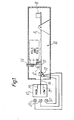
- the apparatus 10 comprises a balanced beam ll,on one side of which is mounted a vibrator 12,comprising a moving coil vibration generator 13 which is a Ling Dynamics Series 101, 3 ohm vibration generator.
- the generator 13 is provided for vibrating a member 14 at a controlled frequency and amplitude.
- a miniature piezo electric accelerometer 15 made by Bruel and Kjaer (Type 4339) is provided for measuring the amplitude of the vibrations of the member 14.
- the generator 13 is mounted on the beam 11 in rubber mountings or on coil springs.
- the beam 11 is provided with a pointer 16 which registers with a fixed scale 17 and the beam has a counter weight 18 which biasses the beam to a position indicated by the top line 19 on the scale 17.
- the patient In use the patient is required to place his finger on the member 14 and push the beam 11 down with a predetermined force of about 0.25 oz. ( 7g.) to bring the pointer in line with the datum 20. Too much pressure on the member 14 moves the beam towards the lower line 21.
- a microswitch 22 is provided alongside the beam 11 so that it is switched to the on position only when the correct force is applied to the beam 11 (i.e. when pointer 16 aligns with the line 20).
- Indicator lights 17 may be provided to indicate to the patient whether the beam is too high, too low or in the correct position.
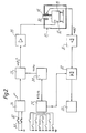
- the vibration generator 13 is driven by an oscillator 24, the output signal of which is a continuous sine wave of uniform amplitude.
- the output signal of the oscillator 24 is fed to a voltage controlled amplifier 25, the gain of which is controlled by a ramp generator 26.
- the output signal of the amplifier 25 is a continuous sine wave of increasing amplitude, and this signal is amplified by a power amplifier 28 to drive the moving coil generator 13 and thereby vibrate the member 14.
- the oscillator 24 is tunable over a range of frequencies by means of a frequency control circuit 29.
- the frequency control circuit 29 is switchable to eight discrete frequency channels. The chosen frequencies are 15 Hz, 30 Hz, 60 Hz, 120 Hz, 240 Hz, 360 Hz, 480 Hz and 720 Hz.
- the vibration of member 14 is monitored by a miniature piezo electric accelerometer manufactured by Bruel and Kjaer - Type 4339.
- the output signal of the accelerometer 16 is a sine wave,the amplitude of which is a measure of the distance moved by the member 14.
- the output signal of the accelerometer 30 is amplified by a charge amplifier 31 and fed to an input of a RMS to DC converter 32.
- the output signal of the frequency control circuit 29 is also fed to an input of the converter 32, and the converter 32 incorporates a comparitor circuit which compares the frequency of the output signal of the frequency control circuit 29 with that of the output signal of the accelerometer 30.
- the output signal of the converter 32 is fed to an input of a digital voltmeter 33 which is scaled to present the voltage level as the amplitude of the vibration of member 14.
- the patient places his finger on the member 14 and pushes the beam 11 down with a force of about 0.25 oz ( 7g. ) until the pointer 16 aligns with the datum 20.
- the doctor selects a frequency which is unknown to the patient and the patient switches on the switch 34.
- the member 14 is vibrated and the ramp generator increases the amplitude gradually. As soon as the patient feels the vibration the patient releases the switch and the amplitude of the vibration displayed on the voltmeter is noted. The test is repeated for different frequencies and the patient's response to the vibration is noted by recording the threshold level of the amplitude that the patient can just feel.
- the ramp generator can be set to control the amplitude of the vibration so that at each selected frequency the amplitude is decreased gradually from a predetermined maximum value.
- the patient switches the apparatus on by switch 34and immediately feels the vibration.
- the amplitude continues to fall gradually until the patient no longer feels the vibration whereupon the patient releases the switch 34 to stop the apparatus and the amplitude of the vibration is noted.
- the ramp generator may be designed to vary the amplitude cyclically. For example, for each selected frequency the amplitude of the vibration of member 14 may be increased gradually towards a maximum value and then decreased.
- the patient switches the apparatus on with switch 34and the apparatus runs continuously.
- the patient is then provided with a second switch 35 which operates a recording device36 see Figure 3.
- the amplitude increases gradually and the patient opens the switch 35 immediately he feels the vibration and the amplitude of the vibration at this point in time is recorded.
- the amplitude then continues to increase to a maximum value whereupon the amplitude is gradually decreased until the patient can no longer feel the vibration.
- the patient then operates switch 35 to operate the recording device to record the amplitude at which he just loses the sense of feel of the vibration.
- the apparatus may be provided with an automatic frequency selection circuit which responds to the operation of the switch 35 by the patient to select different frequencies.
- the apparatus may be operated randomly. That is to say, the doctor may select the same frequency a number of consecutive times, operate the apparatus only on the part of the wave form where the amplitude is increasing, or decreasing, or select different frequencies at random.
- the recording device may be a visual display, e.g. on an oscilliscope, or digital or analogue voltmeter; a video recorder; a pen recorder; or a magnetic tape recording system.
- the selection of frequency may be automated by cyclicly switching electronically to different frequency channels in descending or ascending order. Furthermore, it is not necessary to operate the apparatus on all of the frequency bands mentioned above. For example, to simplify the apparatus, it has been found that frequencies of say 90 Hz, 120Hz, 240 Hz and 400 Hz will provide adequate information to determine cutaneous sensitivity.
Landscapes
- Health & Medical Sciences (AREA)
- Life Sciences & Earth Sciences (AREA)
- Heart & Thoracic Surgery (AREA)
- Medical Informatics (AREA)
- Physics & Mathematics (AREA)
- Veterinary Medicine (AREA)
- Biophysics (AREA)
- Pathology (AREA)
- Engineering & Computer Science (AREA)
- Biomedical Technology (AREA)
- Pain & Pain Management (AREA)
- Public Health (AREA)
- Molecular Biology (AREA)
- Surgery (AREA)
- Animal Behavior & Ethology (AREA)
- General Health & Medical Sciences (AREA)
- Psychiatry (AREA)
- Hospice & Palliative Care (AREA)
- Measurement Of The Respiration, Hearing Ability, Form, And Blood Characteristics Of Living Organisms (AREA)
- Drying Of Semiconductors (AREA)
- Measuring Pulse, Heart Rate, Blood Pressure Or Blood Flow (AREA)
- Information Transfer Between Computers (AREA)
Applications Claiming Priority (2)
| Application Number | Priority Date | Filing Date | Title |
|---|---|---|---|
| GB8124448 | 1981-08-11 | ||
| GB8124448 | 1981-08-11 |
Publications (2)
| Publication Number | Publication Date |
|---|---|
| EP0072255A2 true EP0072255A2 (fr) | 1983-02-16 |
| EP0072255A3 EP0072255A3 (en) | 1985-06-19 |
Family
ID=10523845
Family Applications (1)
| Application Number | Title | Priority Date | Filing Date |
|---|---|---|---|
| EP82304236A Withdrawn EP0072255A3 (en) | 1981-08-11 | 1982-08-11 | An aesthesiometer |
Country Status (2)
| Country | Link |
|---|---|
| EP (1) | EP0072255A3 (fr) |
| JP (1) | JPS5873337A (fr) |
Cited By (2)
| Publication number | Priority date | Publication date | Assignee | Title |
|---|---|---|---|---|
| JPS59156327A (ja) * | 1983-02-25 | 1984-09-05 | 株式会社 東和計測 | 人体振動感覚測定器 |
| WO2006046901A1 (fr) | 2004-10-25 | 2006-05-04 | Vibrosense Dynamics Ab | Dispositif de mesure de perception vibrotactile |
Families Citing this family (3)
| Publication number | Priority date | Publication date | Assignee | Title |
|---|---|---|---|---|
| JPS6292806U (fr) * | 1985-11-30 | 1987-06-13 | ||
| JP5270243B2 (ja) * | 2008-07-18 | 2013-08-21 | リオン株式会社 | 振動感覚測定装置 |
| JP6049224B2 (ja) * | 2015-04-14 | 2016-12-21 | 国立研究開発法人産業技術総合研究所 | 皮膚感覚の評価装置、および皮膚感覚の評価方法 |
Family Cites Families (2)
| Publication number | Priority date | Publication date | Assignee | Title |
|---|---|---|---|---|
| US2742035A (en) * | 1953-02-17 | 1956-04-17 | Goldblatt | Device for determining vibration sensitivity |
| US4175546A (en) * | 1977-09-06 | 1979-11-27 | Ahron P. Leichtman | Device for measuring sensitivity to vibration |
-
1982
- 1982-08-11 EP EP82304236A patent/EP0072255A3/en not_active Withdrawn
- 1982-08-11 JP JP13966282A patent/JPS5873337A/ja active Pending
Cited By (3)
| Publication number | Priority date | Publication date | Assignee | Title |
|---|---|---|---|---|
| JPS59156327A (ja) * | 1983-02-25 | 1984-09-05 | 株式会社 東和計測 | 人体振動感覚測定器 |
| WO2006046901A1 (fr) | 2004-10-25 | 2006-05-04 | Vibrosense Dynamics Ab | Dispositif de mesure de perception vibrotactile |
| EP1809165A4 (fr) * | 2004-10-25 | 2010-05-26 | Vibrosense Dynamics Ab | Dispositif de mesure de perception vibrotactile |
Also Published As
| Publication number | Publication date |
|---|---|
| JPS5873337A (ja) | 1983-05-02 |
| EP0072255A3 (en) | 1985-06-19 |
Similar Documents
| Publication | Publication Date | Title |
|---|---|---|
| US5749372A (en) | Method for monitoring activity and providing feedback | |
| US4817628A (en) | System and method for evaluating neurological function controlling muscular movements | |
| US5311877A (en) | Waking degree maintaining apparatus | |
| US4088125A (en) | Method and apparatus for monitoring skin potential response | |
| JP4505619B2 (ja) | 心身状態判定システム | |
| US5595488A (en) | Apparatus and method for monitoring and improving the alertness of a subject | |
| Craig | Vibrotactile difference thresholds for intensity and the effect of a masking stimulus | |
| US7574007B2 (en) | Stimulus analysis system and method having adaptive artifact rejection | |
| EP0729726A2 (fr) | Dispositif de mesure du pouls | |
| US5803740A (en) | Learning and assessment aid for a severely visually impaired individual | |
| US20020156392A1 (en) | Method and apparatus for inspecting biological rhythms | |
| EP0072255A2 (fr) | Dispositif de détermination de la sensibilité de la peau | |
| US5746205A (en) | Method and apparatus for measuring the working condition of the brain with periodic stimuli | |
| US7717859B2 (en) | Method and combination electronic communication and medical diagnostic apparatus for detecting/monitoring neuropathy | |
| JP3745222B2 (ja) | 振戦計測器 | |
| Wild et al. | Vibrotactile perception thresholds in four non-exposed populations of working age | |
| Dirks et al. | Toward the Specification of Normal Bone‐Conduction Threshold | |
| US6146333A (en) | Acoustic fertility monitor and detector | |
| Kaneko | Comparison between acoustic and mechanical tapping methods for assessing the interfacial states of bone implants | |
| Telage et al. | Testing procedures for measuring oral vibrotactile thresholds: III. Effects obtained using a nonclamping method | |
| Gallichan et al. | High-frequency bone conduction audiometry using a piezoelectric transducer | |
| Espinoza‐Varas et al. | Integration of spectral and temporal cues separated in time and frequency | |
| JP2001059742A (ja) | 歩行データ計測器 | |
| Frank et al. | Coupler output level differences resulting from repeated transducer placement | |
| LaCourse et al. | A high resolution vibrometry system for detecting carpal tunnel syndrome |
Legal Events
| Date | Code | Title | Description |
|---|---|---|---|
| PUAI | Public reference made under article 153(3) epc to a published international application that has entered the european phase |
Free format text: ORIGINAL CODE: 0009012 |
|
| AK | Designated contracting states |
Designated state(s): CH DE FR GB LI SE |
|
| PUAL | Search report despatched |
Free format text: ORIGINAL CODE: 0009013 |
|
| PUAF | Information related to the publication of a search report (a3 document) modified or deleted |
Free format text: ORIGINAL CODE: 0009199SEPU |
|
| AK | Designated contracting states |
Designated state(s): CH DE FR GB LI SE |
|
| D17D | Deferred search report published (deleted) | ||
| STAA | Information on the status of an ep patent application or granted ep patent |
Free format text: STATUS: THE APPLICATION IS DEEMED TO BE WITHDRAWN |
|
| 18D | Application deemed to be withdrawn |
Effective date: 19850301 |
|
| RIN1 | Information on inventor provided before grant (corrected) |
Inventor name: CORNISH, DOUGLAS CECIL |