EP0072267A1 - Aufhängevorrichtung für eine sich hermetisch schliessende Schiebetür - Google Patents
Aufhängevorrichtung für eine sich hermetisch schliessende Schiebetür Download PDFInfo
- Publication number
- EP0072267A1 EP0072267A1 EP82401204A EP82401204A EP0072267A1 EP 0072267 A1 EP0072267 A1 EP 0072267A1 EP 82401204 A EP82401204 A EP 82401204A EP 82401204 A EP82401204 A EP 82401204A EP 0072267 A1 EP0072267 A1 EP 0072267A1
- Authority
- EP
- European Patent Office
- Prior art keywords
- door
- suspension device
- fixed
- guide
- guide rail
- Prior art date
- Legal status (The legal status is an assumption and is not a legal conclusion. Google has not performed a legal analysis and makes no representation as to the accuracy of the status listed.)
- Granted
Links
- 239000000725 suspension Substances 0.000 title claims description 21
- 238000005096 rolling process Methods 0.000 claims abstract description 15
- 230000006835 compression Effects 0.000 claims abstract description 13
- 238000007906 compression Methods 0.000 claims abstract description 13
- 230000010355 oscillation Effects 0.000 claims 1
- 239000011324 bead Substances 0.000 description 2
- 125000006850 spacer group Chemical group 0.000 description 2
- 230000005540 biological transmission Effects 0.000 description 1
- 230000015556 catabolic process Effects 0.000 description 1
- 238000006243 chemical reaction Methods 0.000 description 1
- 238000010276 construction Methods 0.000 description 1
- 238000006073 displacement reaction Methods 0.000 description 1
- 239000000428 dust Substances 0.000 description 1
- 230000002349 favourable effect Effects 0.000 description 1
- 238000004519 manufacturing process Methods 0.000 description 1
- 230000002093 peripheral effect Effects 0.000 description 1
- 230000001681 protective effect Effects 0.000 description 1
- 230000000284 resting effect Effects 0.000 description 1
- 238000007789 sealing Methods 0.000 description 1
Images

Classifications
-
- E—FIXED CONSTRUCTIONS
- E05—LOCKS; KEYS; WINDOW OR DOOR FITTINGS; SAFES
- E05D—HINGES OR SUSPENSION DEVICES FOR DOORS, WINDOWS OR WINGS
- E05D15/00—Suspension arrangements for wings
- E05D15/06—Suspension arrangements for wings for wings sliding horizontally more or less in their own plane
- E05D15/0621—Details, e.g. suspension or supporting guides
- E05D15/0626—Details, e.g. suspension or supporting guides for wings suspended at the top
- E05D15/063—Details, e.g. suspension or supporting guides for wings suspended at the top on wheels with fixed axis
-
- E—FIXED CONSTRUCTIONS
- E05—LOCKS; KEYS; WINDOW OR DOOR FITTINGS; SAFES
- E05D—HINGES OR SUSPENSION DEVICES FOR DOORS, WINDOWS OR WINGS
- E05D15/00—Suspension arrangements for wings
- E05D15/06—Suspension arrangements for wings for wings sliding horizontally more or less in their own plane
- E05D15/10—Suspension arrangements for wings for wings sliding horizontally more or less in their own plane movable out of one plane into a second parallel plane
- E05D15/1021—Suspension arrangements for wings for wings sliding horizontally more or less in their own plane movable out of one plane into a second parallel plane involving movement in a third direction, e.g. vertically
-
- E—FIXED CONSTRUCTIONS
- E05—LOCKS; KEYS; WINDOW OR DOOR FITTINGS; SAFES
- E05D—HINGES OR SUSPENSION DEVICES FOR DOORS, WINDOWS OR WINGS
- E05D15/00—Suspension arrangements for wings
- E05D15/06—Suspension arrangements for wings for wings sliding horizontally more or less in their own plane
- E05D15/10—Suspension arrangements for wings for wings sliding horizontally more or less in their own plane movable out of one plane into a second parallel plane
- E05D15/1042—Suspension arrangements for wings for wings sliding horizontally more or less in their own plane movable out of one plane into a second parallel plane with transversely moving carriage
- E05D2015/1055—Suspension arrangements for wings for wings sliding horizontally more or less in their own plane movable out of one plane into a second parallel plane with transversely moving carriage with slanted or curved track sections or cams
-
- E—FIXED CONSTRUCTIONS
- E05—LOCKS; KEYS; WINDOW OR DOOR FITTINGS; SAFES
- E05Y—INDEXING SCHEME ASSOCIATED WITH SUBCLASSES E05D AND E05F, RELATING TO CONSTRUCTION ELEMENTS, ELECTRIC CONTROL, POWER SUPPLY, POWER SIGNAL OR TRANSMISSION, USER INTERFACES, MOUNTING OR COUPLING, DETAILS, ACCESSORIES, AUXILIARY OPERATIONS NOT OTHERWISE PROVIDED FOR, APPLICATION THEREOF
- E05Y2201/00—Constructional elements; Accessories therefor
- E05Y2201/60—Suspension or transmission members; Accessories therefor
- E05Y2201/622—Suspension or transmission members elements
- E05Y2201/638—Cams; Ramps
-
- E—FIXED CONSTRUCTIONS
- E05—LOCKS; KEYS; WINDOW OR DOOR FITTINGS; SAFES
- E05Y—INDEXING SCHEME ASSOCIATED WITH SUBCLASSES E05D AND E05F, RELATING TO CONSTRUCTION ELEMENTS, ELECTRIC CONTROL, POWER SUPPLY, POWER SIGNAL OR TRANSMISSION, USER INTERFACES, MOUNTING OR COUPLING, DETAILS, ACCESSORIES, AUXILIARY OPERATIONS NOT OTHERWISE PROVIDED FOR, APPLICATION THEREOF
- E05Y2201/00—Constructional elements; Accessories therefor
- E05Y2201/60—Suspension or transmission members; Accessories therefor
- E05Y2201/622—Suspension or transmission members elements
- E05Y2201/684—Rails; Tracks
-
- E—FIXED CONSTRUCTIONS
- E05—LOCKS; KEYS; WINDOW OR DOOR FITTINGS; SAFES
- E05Y—INDEXING SCHEME ASSOCIATED WITH SUBCLASSES E05D AND E05F, RELATING TO CONSTRUCTION ELEMENTS, ELECTRIC CONTROL, POWER SUPPLY, POWER SIGNAL OR TRANSMISSION, USER INTERFACES, MOUNTING OR COUPLING, DETAILS, ACCESSORIES, AUXILIARY OPERATIONS NOT OTHERWISE PROVIDED FOR, APPLICATION THEREOF
- E05Y2201/00—Constructional elements; Accessories therefor
- E05Y2201/60—Suspension or transmission members; Accessories therefor
- E05Y2201/622—Suspension or transmission members elements
- E05Y2201/688—Rollers
- E05Y2201/69—Rollers having inclined axes
-
- E—FIXED CONSTRUCTIONS
- E05—LOCKS; KEYS; WINDOW OR DOOR FITTINGS; SAFES
- E05Y—INDEXING SCHEME ASSOCIATED WITH SUBCLASSES E05D AND E05F, RELATING TO CONSTRUCTION ELEMENTS, ELECTRIC CONTROL, POWER SUPPLY, POWER SIGNAL OR TRANSMISSION, USER INTERFACES, MOUNTING OR COUPLING, DETAILS, ACCESSORIES, AUXILIARY OPERATIONS NOT OTHERWISE PROVIDED FOR, APPLICATION THEREOF
- E05Y2800/00—Details, accessories and auxiliary operations not otherwise provided for
- E05Y2800/26—Form or shape
- E05Y2800/298—Form or shape having indentations
-
- E—FIXED CONSTRUCTIONS
- E05—LOCKS; KEYS; WINDOW OR DOOR FITTINGS; SAFES
- E05Y—INDEXING SCHEME ASSOCIATED WITH SUBCLASSES E05D AND E05F, RELATING TO CONSTRUCTION ELEMENTS, ELECTRIC CONTROL, POWER SUPPLY, POWER SIGNAL OR TRANSMISSION, USER INTERFACES, MOUNTING OR COUPLING, DETAILS, ACCESSORIES, AUXILIARY OPERATIONS NOT OTHERWISE PROVIDED FOR, APPLICATION THEREOF
- E05Y2900/00—Application of doors, windows, wings or fittings thereof
- E05Y2900/10—Application of doors, windows, wings or fittings thereof for buildings or parts thereof
- E05Y2900/13—Type of wing
- E05Y2900/132—Doors
Definitions
- the present invention relates to watertight sliding doors and their suspension devices, such doors being used, in particular for enclosures in which a determined temperature and / or atmosphere must be maintained.
- the door support means essentially consists of a traction arm, a first end of which cooperates with a first guide member secured to the wall, with respect to which it can move angularly and in translation and the other end of which supports the door itself in oscillating fashion.
- the device also comprises a second guide rail fixed to the wall, the guide surface of which delimits at least one ramp or a notch with which at least one roller or rolling or sliding element cooperates carried by means of supporting the door.
- the angle formed by the traction arm with the horizontal allows when the roller located on the second guide rail falls into a notch, to generate a force for applying the door on the frame equal to 1.4 to 1.7 times the weight of the door, which naturally favors obtaining a good seal.
- This improvement consists in replacing the two guide rails by a C-shaped profile fixed against the wall, the edge of the lower wing of the C forming the surface of said second guide rail, and the upper part of the C delimiting a surface of bearing diri inwardly of the profile and constituting said first guide rail.
- the object of the present invention is to provide improvements to the above devices with a view to obtaining a more compact device, greater closing efficiency, and a better external appearance, while reducing its cost price.
- the present invention relates to a device for suspending a watertight sliding door.
- a guide rail having a cross section in the general shape of C, fixed to a wall and delimiting two guide surfaces, one of which comprises at least one ramp or a notch with which at least one roller or other rolling element cooperates or sliding carried by door support means and the other of which cooperates with at least one roller or other rolling element or sliding carried by a swing arm connected to the door, characterized in that the or each swing arm is disposed entirely inside the C-section rail and works in compression.
- the ends of the C formed by the lower and upper edges of the C are arranged in an approximately horizontal plane and the guide surfaces situated at said ends of the C are approximately perpendicular to each other.
- the door is mounted on fittings connected in an oscillating manner to the compression arm and which support the or each rolling or sliding element cooperating with the first guide surface.
- the compression arms are inclined to the horizontal by an angle less than 45 ° when the door is in the closed position.
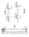
- Door P and its suspension devices are shown diagrammatically in FIGS. 1 and 2A, 2B.
- the door P is suspended from a guide rail 1 by means of suspension devices S each comprising two rollers G 1 and G 2 which ensure the longitudinal movement of the door, by rolling on the guide rail.
- suspension devices S each comprising two rollers G 1 and G 2 which ensure the longitudinal movement of the door, by rolling on the guide rail.
- notches 2 In the guide rail are provided notches 2 into which the rollers G 1 fall when the door is in the closed position of FIG. 2A.
- each suspension device S and its cooperation with the door P and the guide rail are shown in Fig.3 to 5.
- the door is shown in the open position in Fig.3. It is shown in the closed position resting on its sealing beads B in Fig. 4.
- the guide rail 1 is constituted by a C-shaped section lying down, open downwards, and kept applied to the wall M by a first wing la, by means of a fitting 4 and a wing 5a of a bracket 5, the assembly being tightened by a screw 6 which passes through them and is screwed into the wall M.
- the guide rail 1 is also fixed by its upper core 1b to the upper wing 5b of the bracket 5 by means of a fixing means 7, so that the core 1b is planar and approximately horizontal. .
- the free end 1c of the wing 1a of the rail 1 is folded obliquely towards the interior of the C and forms an angle close to 45 ° with the horizontal so as to constitute a plane guide surface 8 internal to the profile C.
- the guide surface 8 and the wing also have it Lement in two predetermined locations the notches 2 which can be seen in Fig.4.
- the wing of C opposite the wall M comprises two parts Id and forming between them an obtuse angle.
- the part Id is adjacent to the core Ib.
- the part it extends parallel to the wing la and ends at its free end by a flange 1f directed towards the inside of the profile, this flange delimiting in the angle formed internally with the adjacent part 1c, a rolling surface 9 of circular arc section located inside the guide rail 1 and thus constituting a second guide surface whose mean plane is approximately perpendicular to the guide surface 8.
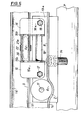
- the oblique wing 13a also supports a roller support device G 2 composed of two brackets 15 and 16, (Fig.5) with perpendicular wings.
- the wings 15a and 16a of these brackets are fixed to the wing 13a by means of clamping means 17 and 18.
- the other wings 15b and 16b are held apart apart from one another by a spacer 19 and a rod 20, the longitudinal axes of the spacer 19 and of the rod 20 being arranged parallel to the longitudinal axis of the guide rail 1.
- On the rod 20 is articulated the core 21a of a compression arm 21 in the form of yoke between the legs 21b and 21c from which pivots, on a rod 22 perpendicular to the rod 20, the roller G 2 .
- This roller G 2 rests on the rolling surface 9 and has a toroidal peripheral surface, which allows an angular displacement of the axis of the roller G 2 relative to the surface 9.
- the rod 20 is located above the rollers G and G 2 , near the core 1b of C; the mean planes of the two rollers intersect in the vicinity of this rod and are inclined at approximately the same angle on the vertical.
- the device When the door is in translation position, that is to say in partial or total opening position, the device has the configuration shown in Fig.3.
- the rollers G 1 , G 2 roll respectively along their guide path 8 and 9.
- the rollers G 1 fall into the notches 2 wing Ia, causing the door to move to the floor and to the wall.
- the angle formed by the mean planes of the rollers G 1 and G 2 increases by a value d of about 1 5 ° to take the position shown in Fig.4 where we can see that the rollers G 2 have tilted around their fulcrum on the rolling surface 9.
- Fig.l one can examine how the forces are broken down when the door is in the closed position.
- the weight Po of the door, transmitted by the profile 13, is exerted on the rod 20. Its line of action, from this rod passes between the rollers G 1 and G 2 . If it is assumed that the rolling surface 8 practically does not intervene in the transmission of forces, which is actually the case in reality due to the support of the beads B on the wall M, the weight Po of the door can be broken down into a component P T directed along the compression arm 21 and a horizontal component P H.
- the door In its lower part, the door is guided by rollers 22 of conical shape and vertical axis, whose generator closest to the wall is inclined relative to vertical to the above-mentioned angle ⁇ . In this way, the reaction exerted by the wall on the lower part of the door is absorbed by the lower guide rollers.
- the compression arm 21 makes an angle ⁇ with the horizontal when the door is in the closed position and an angle ⁇ + ⁇ when the latter is in the open position.
- the angle of inclination of the compression arm with the horizontal is therefore minimal when the door is in the closed position, and this situation is naturally favorable to greater efficiency of the closing force of the door. It will be noted that with the device of the invention as just described, it is always possible to obtain any values of 3 between 0 and 45 ° by increasing for example the distance between the two wings of the C and / or by raising the edge If of the same profile.
Landscapes
- Engineering & Computer Science (AREA)
- Mechanical Engineering (AREA)
- Support Devices For Sliding Doors (AREA)
- Specific Sealing Or Ventilating Devices For Doors And Windows (AREA)
Applications Claiming Priority (2)
| Application Number | Priority Date | Filing Date | Title |
|---|---|---|---|
| FR8115209 | 1981-08-05 | ||
| FR8115209A FR2511070A1 (fr) | 1981-08-05 | 1981-08-05 | Dispositif de suspension d'une porte etanche coulissante |
Publications (2)
| Publication Number | Publication Date |
|---|---|
| EP0072267A1 true EP0072267A1 (de) | 1983-02-16 |
| EP0072267B1 EP0072267B1 (de) | 1985-10-02 |
Family
ID=9261198
Family Applications (1)
| Application Number | Title | Priority Date | Filing Date |
|---|---|---|---|
| EP82401204A Expired EP0072267B1 (de) | 1981-08-05 | 1982-06-29 | Aufhängevorrichtung für eine sich hermetisch schliessende Schiebetür |
Country Status (4)
| Country | Link |
|---|---|
| US (1) | US4476652A (de) |
| EP (1) | EP0072267B1 (de) |
| DE (1) | DE3266676D1 (de) |
| FR (1) | FR2511070A1 (de) |
Cited By (7)
| Publication number | Priority date | Publication date | Assignee | Title |
|---|---|---|---|---|
| GB2162225A (en) * | 1984-07-18 | 1986-01-29 | Genaplast Pty Ltd | Sliding door mechanism |
| FR2618179A1 (fr) * | 1987-07-17 | 1989-01-20 | Markus Hermetische Deuren | Ensemble de porte coulissante. |
| FR2631072A1 (fr) * | 1988-05-04 | 1989-11-10 | Fermod | Dispositif de suspension de porte coulissante |
| WO1994019570A1 (en) * | 1993-02-16 | 1994-09-01 | Global Financial Ltd. | Pivotable structure |
| CN101048564B (zh) * | 2004-10-26 | 2011-08-10 | 卡巴吉尔根股份公司 | 用于密封的滑动门的悬挂设备和滑架 |
| ES2570587A1 (es) * | 2014-11-17 | 2016-05-19 | Decoracion Y Confort Del Bano S A | Mampara para plato de ducha o bañera |
| EP3822441A1 (de) * | 2019-11-13 | 2021-05-19 | Kaviflex, S.L. | Sicherheitsführungssatz für schiebetüren |
Families Citing this family (27)
| Publication number | Priority date | Publication date | Assignee | Title |
|---|---|---|---|---|
| US4680828A (en) * | 1984-04-02 | 1987-07-21 | Standard-Keil Hardware Manufacturing Co. | Hardware for mounting a sliding door panel |
| US4852628A (en) * | 1987-04-27 | 1989-08-01 | Labex Gmbh | Suspension system for folding door |
| FI81879C (fi) * | 1989-04-07 | 1993-02-11 | Nikai Innovaatio Oy | Svaengbar balkongglasningskonstruktion |
| US4936049A (en) * | 1989-06-26 | 1990-06-26 | Hansen Leslie N | Airtight door |
| JPH0552072A (ja) * | 1991-08-16 | 1993-03-02 | Masaaki Kamezaki | 大形冷凍庫等用スライデイング式ドア |
| CA2076477C (en) * | 1992-08-21 | 1995-11-07 | Jean-Pierre Gingras | Door closure for refrigeration housing |
| JPH07224570A (ja) * | 1994-02-15 | 1995-08-22 | Masaaki Kamezaki | 大形冷凍庫等用スライディング式ドア装置 |
| US6142082A (en) * | 1998-12-22 | 2000-11-07 | Burke; Michael K. | Guide bracket for doors on railroad cars |
| US6336248B1 (en) * | 2000-05-05 | 2002-01-08 | Kason Industries, Inc. | Suspension system for sliding door |
| US6745813B2 (en) | 2000-07-31 | 2004-06-08 | Kim Charles Yorgason | Rolling pivot for track suspended articulated panels |
| US7422249B2 (en) * | 2000-12-22 | 2008-09-09 | Glover J Raymond | Gliding door, latch mechanism and method |
| DE10210812B4 (de) * | 2002-03-12 | 2005-06-16 | Dorma Gmbh + Co. Kg | Trag- und Führungseinrichtung zum Halten von ortsveränderlichen, hängend gelagerten Tür- oder Wandelementen |
| US20030221582A1 (en) * | 2002-04-08 | 2003-12-04 | Burke Michael K. | Auto rack railroad car end door stabilizer |
| AU2003265918A1 (en) * | 2002-09-03 | 2004-03-29 | Rytec Corporation | Dual overhead track for a sliding door |
| US20060090401A1 (en) * | 2003-01-10 | 2006-05-04 | Jamison Door Company | Air heated, flexible door panel |
| DE20306219U1 (de) * | 2003-04-19 | 2003-06-12 | Hespe & Woelm GmbH & Co KG, 42579 Heiligenhaus | Tragschiene |
| US20070227074A1 (en) * | 2006-04-04 | 2007-10-04 | Terry Frank | Enclosed sliding door assembly |
| US8375645B2 (en) * | 2007-03-05 | 2013-02-19 | Niitech Co., Ltd. | Sliding door device |
| US7610718B2 (en) * | 2007-11-15 | 2009-11-03 | Krueger International, Inc. | Sliding door with lateral sealing movement |
| SI2685039T1 (sl) * | 2012-07-11 | 2020-01-31 | Hawa Sliding Solutions Ag | Vodilna naprava, tekalni mehanizem in tekalna tirnica |
| DE202013001827U1 (de) * | 2013-02-26 | 2013-03-07 | Rippert Besitzgesellschaft Mbh & Co. Kg | Portal für eine Trocknungsvorrichtung |
| US9462915B2 (en) | 2013-03-15 | 2016-10-11 | Kohler Co. | Shower door cam system |
| CA2842446C (en) | 2014-02-10 | 2020-04-14 | Dynamic Closures Corp. | Folding door trolley |
| US10125528B2 (en) * | 2014-10-03 | 2018-11-13 | Zdzislaw Stanislaw Wypych | Easy glide storm door |
| US10570662B2 (en) * | 2017-05-19 | 2020-02-25 | Mechoshade Systems, Llc | Wheel carriage assembly for guided asymmetric fabric deployment |
| JP6890473B2 (ja) * | 2017-05-31 | 2021-06-18 | 株式会社ダイフク | スライド式防火扉 |
| US11840872B1 (en) * | 2021-02-04 | 2023-12-12 | Roy Ben David | Non-hinged door system and method of conversion of a hinged door into a non-hinged door |
Citations (2)
| Publication number | Priority date | Publication date | Assignee | Title |
|---|---|---|---|---|
| FR1525808A (fr) * | 1966-06-07 | 1968-05-17 | Eltreva Ag | Dispositif à roulettes pour le montage de fenêtres à coulisse |
| DE2616495A1 (de) * | 1976-04-14 | 1977-10-27 | Niederberger Kg Heinrich | Schiebetuer fuer kuehlraeume |
Family Cites Families (2)
| Publication number | Priority date | Publication date | Assignee | Title |
|---|---|---|---|---|
| US2740168A (en) * | 1953-05-25 | 1956-04-03 | Charles S Wright | Closure sealing apparatus |
| GB1572638A (en) * | 1978-04-11 | 1980-07-30 | Watkins C | Sliding door track mechanism |
-
1981
- 1981-08-05 FR FR8115209A patent/FR2511070A1/fr active Granted
-
1982
- 1982-06-29 EP EP82401204A patent/EP0072267B1/de not_active Expired
- 1982-06-29 DE DE8282401204T patent/DE3266676D1/de not_active Expired
- 1982-07-27 US US06/402,331 patent/US4476652A/en not_active Expired - Fee Related
Patent Citations (2)
| Publication number | Priority date | Publication date | Assignee | Title |
|---|---|---|---|---|
| FR1525808A (fr) * | 1966-06-07 | 1968-05-17 | Eltreva Ag | Dispositif à roulettes pour le montage de fenêtres à coulisse |
| DE2616495A1 (de) * | 1976-04-14 | 1977-10-27 | Niederberger Kg Heinrich | Schiebetuer fuer kuehlraeume |
Cited By (9)
| Publication number | Priority date | Publication date | Assignee | Title |
|---|---|---|---|---|
| GB2162225A (en) * | 1984-07-18 | 1986-01-29 | Genaplast Pty Ltd | Sliding door mechanism |
| FR2618179A1 (fr) * | 1987-07-17 | 1989-01-20 | Markus Hermetische Deuren | Ensemble de porte coulissante. |
| BE1002467A3 (nl) * | 1987-07-17 | 1991-02-19 | Markus Hermetische Deuren | Schuifdeur en ondersteuningsmiddelen daarvoor. |
| FR2631072A1 (fr) * | 1988-05-04 | 1989-11-10 | Fermod | Dispositif de suspension de porte coulissante |
| WO1994019570A1 (en) * | 1993-02-16 | 1994-09-01 | Global Financial Ltd. | Pivotable structure |
| US6065247A (en) * | 1993-02-16 | 2000-05-23 | Global Financial Ltd. | Pivotable structure |
| CN101048564B (zh) * | 2004-10-26 | 2011-08-10 | 卡巴吉尔根股份公司 | 用于密封的滑动门的悬挂设备和滑架 |
| ES2570587A1 (es) * | 2014-11-17 | 2016-05-19 | Decoracion Y Confort Del Bano S A | Mampara para plato de ducha o bañera |
| EP3822441A1 (de) * | 2019-11-13 | 2021-05-19 | Kaviflex, S.L. | Sicherheitsführungssatz für schiebetüren |
Also Published As
| Publication number | Publication date |
|---|---|
| DE3266676D1 (en) | 1985-11-07 |
| EP0072267B1 (de) | 1985-10-02 |
| FR2511070A1 (fr) | 1983-02-11 |
| US4476652A (en) | 1984-10-16 |
| FR2511070B1 (de) | 1983-12-09 |
Similar Documents
| Publication | Publication Date | Title |
|---|---|---|
| EP0072267B1 (de) | Aufhängevorrichtung für eine sich hermetisch schliessende Schiebetür | |
| FR2758850A1 (fr) | Cassette leve-vitre de porte de vehicule | |
| FR2911619A1 (fr) | Dispositif a caisson mobile. | |
| FR2631072A1 (fr) | Dispositif de suspension de porte coulissante | |
| EP1722052A1 (de) | Schloss für eine Eingangstür in einem Sektionaltor, insbesondere für Garagen | |
| EP0235018B1 (de) | Führungsvorrichtung für einen Schwenk-Schiebeflügel, insbesondere für Fahrzeugtüren | |
| FR2579661A1 (fr) | Perfectionnements aux dispositifs de stores formant velums | |
| FR2588038A1 (fr) | Dispositif pour la fixation, au chassis dormant d'une fenetre, d'un caisson portant le mecanisme complet d'un store enroulable ou d'un volet roulant | |
| FR2493451A1 (fr) | Rail formant support pour un dispositif d'entrainement a chaine | |
| FR2681898A1 (fr) | Ferrure pour le montage de portes coulissantes. | |
| FR2846028A1 (fr) | Dispositif d'articulation d'un battant d'une porte | |
| CH617745A5 (en) | Balancing device for tip-up doors | |
| FR2608527A1 (fr) | Baie a volet abattant notamment pour autocars | |
| EP0047194B1 (de) | Türgriff mit Betätigungsklappe, insbesondere für Kraftfahrzeuge | |
| EP0319357B1 (de) | Ranchabzugs- oder analoge Dachöffnung mit grossen Öffnungsweg des Schlussdeckels | |
| FR3120998A1 (fr) | Appareil électrique encastrable | |
| FR2578893A1 (fr) | Porte basculante, notamment porte de garage | |
| EP0976908A1 (de) | Rafflamellenstore | |
| EP0143722B1 (de) | Kraftfahrzeugtür mit Schiebefenster | |
| FR2844541A1 (fr) | Dispositif de fermeture etanche d'une porte coulissante | |
| FR2585645A1 (fr) | Rideau coulissant pour caisse de vehicule de transport routier et vehicule equipe de tels rideaux | |
| EP0132721A1 (de) | Befestigungsvorrichtung für Sessellift oder Kabine an einem Kabel mit Rollenlauffläche | |
| FR2492355A1 (fr) | Monte-charge | |
| FR2516154A1 (fr) | Cadre-support de vitrage pour fenetre | |
| FR2653419A1 (fr) | Dispositif pour le soulevement de charges et, notamment, pour le soulevement de meubles et de portes. |
Legal Events
| Date | Code | Title | Description |
|---|---|---|---|
| PUAI | Public reference made under article 153(3) epc to a published international application that has entered the european phase |
Free format text: ORIGINAL CODE: 0009012 |
|
| AK | Designated contracting states |
Designated state(s): DE GB IT NL |
|
| 17P | Request for examination filed |
Effective date: 19830205 |
|
| ITF | It: translation for a ep patent filed | ||
| GRAA | (expected) grant |
Free format text: ORIGINAL CODE: 0009210 |
|
| AK | Designated contracting states |
Designated state(s): DE GB IT NL |
|
| REF | Corresponds to: |
Ref document number: 3266676 Country of ref document: DE Date of ref document: 19851107 |
|
| PLBE | No opposition filed within time limit |
Free format text: ORIGINAL CODE: 0009261 |
|
| STAA | Information on the status of an ep patent application or granted ep patent |
Free format text: STATUS: NO OPPOSITION FILED WITHIN TIME LIMIT |
|
| 26N | No opposition filed | ||
| ITTA | It: last paid annual fee | ||
| PGFP | Annual fee paid to national office [announced via postgrant information from national office to epo] |
Ref country code: NL Payment date: 20010517 Year of fee payment: 20 |
|
| PGFP | Annual fee paid to national office [announced via postgrant information from national office to epo] |
Ref country code: DE Payment date: 20010521 Year of fee payment: 20 |
|
| PGFP | Annual fee paid to national office [announced via postgrant information from national office to epo] |
Ref country code: GB Payment date: 20010622 Year of fee payment: 20 |
|
| REG | Reference to a national code |
Ref country code: GB Ref legal event code: IF02 |
|
| PG25 | Lapsed in a contracting state [announced via postgrant information from national office to epo] |
Ref country code: GB Free format text: LAPSE BECAUSE OF EXPIRATION OF PROTECTION Effective date: 20020628 |
|
| PG25 | Lapsed in a contracting state [announced via postgrant information from national office to epo] |
Ref country code: NL Free format text: LAPSE BECAUSE OF EXPIRATION OF PROTECTION Effective date: 20020629 |
|
| REG | Reference to a national code |
Ref country code: GB Ref legal event code: PE20 Effective date: 20020628 |
|
| NLV7 | Nl: ceased due to reaching the maximum lifetime of a patent |
Effective date: 20020629 |