EP0072320A2 - Dachfenster in Schwenkflügelbauweise - Google Patents
Dachfenster in Schwenkflügelbauweise Download PDFInfo
- Publication number
- EP0072320A2 EP0072320A2 EP82401475A EP82401475A EP0072320A2 EP 0072320 A2 EP0072320 A2 EP 0072320A2 EP 82401475 A EP82401475 A EP 82401475A EP 82401475 A EP82401475 A EP 82401475A EP 0072320 A2 EP0072320 A2 EP 0072320A2
- Authority
- EP
- European Patent Office
- Prior art keywords
- frame
- leaf
- axis
- upright
- integral
- Prior art date
- Legal status (The legal status is an assumption and is not a legal conclusion. Google has not performed a legal analysis and makes no representation as to the accuracy of the status listed.)
- Withdrawn
Links
Images



Classifications
-
- E—FIXED CONSTRUCTIONS
- E05—LOCKS; KEYS; WINDOW OR DOOR FITTINGS; SAFES
- E05D—HINGES OR SUSPENSION DEVICES FOR DOORS, WINDOWS OR WINGS
- E05D15/00—Suspension arrangements for wings
- E05D15/48—Suspension arrangements for wings allowing alternative movements
-
- E—FIXED CONSTRUCTIONS
- E04—BUILDING
- E04D—ROOF COVERINGS; SKY-LIGHTS; GUTTERS; ROOF-WORKING TOOLS
- E04D13/00—Special arrangements or devices in connection with roof coverings; Protection against birds; Roof drainage ; Sky-lights
- E04D13/03—Sky-lights; Domes; Ventilating sky-lights
- E04D13/035—Sky-lights; Domes; Ventilating sky-lights characterised by having movable parts
- E04D13/0357—Sky-lights; Domes; Ventilating sky-lights characterised by having movable parts the parts pivoting about an axis supported on a hinged frame or arms
-
- E—FIXED CONSTRUCTIONS
- E05—LOCKS; KEYS; WINDOW OR DOOR FITTINGS; SAFES
- E05F—DEVICES FOR MOVING WINGS INTO OPEN OR CLOSED POSITION; CHECKS FOR WINGS; WING FITTINGS NOT OTHERWISE PROVIDED FOR, CONCERNED WITH THE FUNCTIONING OF THE WING
- E05F1/00—Closers or openers for wings, not otherwise provided for in this subclass
- E05F1/08—Closers or openers for wings, not otherwise provided for in this subclass spring-actuated, e.g. for horizontally sliding wings
- E05F1/10—Closers or openers for wings, not otherwise provided for in this subclass spring-actuated, e.g. for horizontally sliding wings for swinging wings, e.g. counterbalance
- E05F1/1041—Closers or openers for wings, not otherwise provided for in this subclass spring-actuated, e.g. for horizontally sliding wings for swinging wings, e.g. counterbalance with a coil spring perpendicular to the pivot axis
- E05F1/1066—Closers or openers for wings, not otherwise provided for in this subclass spring-actuated, e.g. for horizontally sliding wings for swinging wings, e.g. counterbalance with a coil spring perpendicular to the pivot axis with a traction spring
- E05F1/1075—Closers or openers for wings, not otherwise provided for in this subclass spring-actuated, e.g. for horizontally sliding wings for swinging wings, e.g. counterbalance with a coil spring perpendicular to the pivot axis with a traction spring for counterbalancing
-
- E—FIXED CONSTRUCTIONS
- E05—LOCKS; KEYS; WINDOW OR DOOR FITTINGS; SAFES
- E05Y—INDEXING SCHEME ASSOCIATED WITH SUBCLASSES E05D AND E05F, RELATING TO CONSTRUCTION ELEMENTS, ELECTRIC CONTROL, POWER SUPPLY, POWER SIGNAL OR TRANSMISSION, USER INTERFACES, MOUNTING OR COUPLING, DETAILS, ACCESSORIES, AUXILIARY OPERATIONS NOT OTHERWISE PROVIDED FOR, APPLICATION THEREOF
- E05Y2800/00—Details, accessories and auxiliary operations not otherwise provided for
-
- E—FIXED CONSTRUCTIONS
- E05—LOCKS; KEYS; WINDOW OR DOOR FITTINGS; SAFES
- E05Y—INDEXING SCHEME ASSOCIATED WITH SUBCLASSES E05D AND E05F, RELATING TO CONSTRUCTION ELEMENTS, ELECTRIC CONTROL, POWER SUPPLY, POWER SIGNAL OR TRANSMISSION, USER INTERFACES, MOUNTING OR COUPLING, DETAILS, ACCESSORIES, AUXILIARY OPERATIONS NOT OTHERWISE PROVIDED FOR, APPLICATION THEREOF
- E05Y2900/00—Application of doors, windows, wings or fittings thereof
- E05Y2900/10—Application of doors, windows, wings or fittings thereof for buildings or parts thereof
- E05Y2900/13—Type of wing
- E05Y2900/148—Windows
- E05Y2900/152—Roof windows
Definitions
- the present invention relates to a folding window comprising a frame, a first leaf which can be folded down on the frame and a second leaf carrying the glazing and which can rotate relative to the first leaf, the axis of rotation of the second leaf relative to the first leaf being located. at the free end of the latter.
- the invention relates to elastic means provided between the frame and the first leaf, which allows cost reduction and safe operation.
- the invention also relates to simple hinges making it possible to provide dormers with a single leaf which can easily pivot by almost 180 °.
- the elastic means provided between the frame and the first leaf comprise a rod pivotally mounted on a pin fixed on the external face of an amount of the first leaf and the other end of which is articulated at the end of '' a rod to which is fixed at an intermediate point one end of a tension spring whose other end is fixed on the internal face of the upright adjacent to the frame, a stopper being fixed on said upright di: frame below the connection point between the spring and the rod, the spring pressing the rod against the stopper, the materials of the rod and the stopper being such that the stopper acts as a brake, the point of attachment of the spring on the upright of the frame being high enough to recall the link against the rebate of the amount of the first leaf.
- the elastic means comprise a link, one end of which pivots on an axis fixed on the external face of an upright of the first leaf and the other end of which is articulated on the end of a second link, the other of which end is articulated on a slide which can slide in a U-shaped slide, open upwards, fixed on the adjacent upright of the frame, the slide being recalled towards the top of the upright of the frame by a spring, the materials of the slide and the slide being such that the slide acts as a brake.
- connection between the slide and the spring comprises a screw screwed into a threaded hole in the slide, in alignment with the spring, hooking means being provided between the end of the screw and the spring.
- the hinges between the frame and the first leaf are respectively placed between the outer faces of the uprights of the first leaf and the lower faces of the uprights of the frame, each hinge being formed. by a first metal plate secured to the upright of the frame and a second metal plate secured to the upright of the first leaf, the two plates being connected by a pair of rods whose ends pivot around axes mounted on the plates, the line of the axes carried by the amount of the frame making substantially an acute angle of 45 °, open upwards, with the plane of the frame, the connecting rod, shorter, the closest to the upper side of the frame being, in the closed position practically perpendicular to the plane of the frame, the other rod, longer, forming-with the first an acute angle, open downwards, the opening operation of the first leaf causing the rods to rotate downwards.
- each hinge is constituted by a first metal plate integral with the amount of the frame and a second metal plate integral with the amount of the first leaf, the two plates being connected by a set of three rods, the first two of which are articulated at their adjacent ends and the other ends of which are pivotally mounted on the first and second plates, the third rod having a end pivotally mounted on the second plate, an intermediate point pivotally mounted on an intermediate point of the first link and its other end slidably mounted in a groove traced in the first plate.
- the hinge system comprises a first axis integral with the upright of the frame and a second axis, the axes being parallel to each other and being connected by a spacer integral with the second axis, the first axis carrying a first pinion fixed relative to to it and the second axis carrying a second pinion pivoting with respect to it, the pinions being meshed, the second pinion being integral with the leaf.
- the hinge system comprises a first axis secured to the upright of the frame and a second axis secured to the leaf, the axes carrying bearings connected by a spacer, the first axis carrying a first free pinion and the second axis carrying a second pinion of which it is integral, the pinions being meshed.
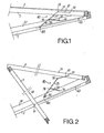
- the dormer window in Figs. 1 and 2 consists of a fixed frame 1, a first folding leaf 2 and a second leaf 3 carrying the glazing.
- Fig. 1 the leaf 3 is assumed to be locked relative to the leaf 2 and the latter free relative to the frame 1. Under these conditions, a system of elastic means 48 keeps the leaf 2 open.
- the system 48 comprises a link 49 which can, at one of its ends, pivot around an axis 50 fixed on the external face of the upright 51 of the leaf 2.
- the other end 52 of the link 49 is supported on the edge of the rebate of the upright 51.
- On the end 52 is mounted an axis around which the end of a relatively long rod 53 can pivot.
- the end of a tension spring 55 is fixed, the other end of which is fixed, at 56, to the internal face of the upright 57 of the frame 1.
- a stop 58 is fixed against which the spring 55 applies the lower part of the rod 53.
- the weight of leaf 2 is transmitted by the rebate of 51 to the rod 49, then by the rod 53 to the stop 58.
- the coefficient of friction between the materials of the rod 53 and of the stop 58, as well as the shape of the contact surface between the two parts, are chosen so as to act as a brake in any position.
- the uprights 51 and / or 57 comprise, throughout the zone where the rod 53 and the link 49 move, thickness reductions to leave the clearance necessary for the movements of 53 and 49.
- a flat or a metal angle 60 forming rebate, which defines by its horizontal face facing inward a bearing surface for the shoulder 61 of the upright 62 of leaf 3, as will be seen in relation to FIG. 2.
- the length of the plate or the angle 60 can be limited.
- wing 2 is free with respect to the frame 1 and that the wing 3 is free with respect to the wing 2.
- the wing 3 pivots down until the shoulder 61 rests on the upper face of the angle iron 60.
- the shoulder is slid until, for example, reaching the position shown in FIG. 2.
- the leaf 2 then pivoted upwards, driven by 2, so that the end 52 of the link no longer rests on the edge of the rebate of the upright 51.
- the free end 108 of the rod 53 ends in the form of a hook which hooks behind the stop 58.
- the length of the link 49, plus that of the rod 53 defines the limit position that is desired for the pivoting of the leaf 2.
- a hinge system 63 With a solid line drawing defining the open position of the system, a dashed line drawing an intermediate position, and a dashed line drawing the closed position.
- the system 63 consists of two plates 64 and 65 which are joined by two short links 66 and 67.
- the plate 64 is assumed to be applied to the amount of the fixed frame while the plate 65 is applied to the amount of the movable, fixed and mobile being understood in their relative sense.
- One end of the rod 66 can rotate around an axis 68 integral with the plate 64 while its other end can rotate around an axis 69 integral with the plate 65.
- One end of the rod 67 can rotate around a axis 70 secured to the plate 64 while its other end can rotate around an axis 71 secured to the plate 65.
- the axes 68 and 70 are obviously fixed, like the plate 64 which is secured to the upright 57 of the fixed frame 1. So the axes 68 form the vertices of a deformable quadrilateral having a fixed side 68-70 and two sides, embodied by 66 and 67, which have fixed lengths.
- the approximate distances between axes are 35 mm between 68 and 70, 29 mm between 70 and 71, 24 mm between 68 and 69, and 16 mm between 69 and 71 If you change the size of the hinge system, you keeps the different relationships between these distances.
- the instantaneous center of rotation of the plate 65 is, at the start of the opening, clearly above the upper edge of the plate 64 which is fixed to the upright. fixed of the fixed frame, then descends approximately to the level of the upper edge of the plate 64, at the end of 90 ° opening. So, we obtain; a disengagement of the movable frame relative to the fixed frame which allows to place sheets of coating against rain only on the upper crossmember of the fixed frame.
- the opening angle is greater and, also, the system can be placed not at the end of the upright, but in the middle zone and therefore be directly usable on single casement frames pivoting through the middle.
- FIG. 4 there is shown another hinge system 72 in the closed position.
- the system 72 consists of two plates 73 and 74, the first on the fixed part and the other on the mobile part, which are joined by two links 75 and 76.
- One end of the link 75 can rotate around an axis 77 secured to the plate 73 while its other end carries an axis 78 on which another link 79 is articulated.
- One end of the link 76 can rotate around an axis 80 secured to the plate 74 while its intermediate part can rotate around an axis 81 integral with the middle part of the link 75 'and that its other end carries a lug 82 which slides in a slot 83 of the plate 73.
- the other end of the link 79 can rotate around 'an axis 84' integral with the plate 74.
- the approximate dimensions are as follows: between 77 and 78, 21 mm; between 77 and 81, 11 mm; between 81 and 78, 18 mm; between 78 and 84, 19 mm; between 80 and 84, 14 mm; between 80 and 81, 16 mm; between 81 and 82, 32 mm; and between 80 and 82, 38 mm. It therefore appears that, on the link 75, the points 77, 81 and 78 are not aligned, but form a very flat triangle, the obtuse angle of 81 is open towards the plate 74.
- the points 80, 81 and 82 are not aligned, but form a flattened triangle, the obtuse angle at 81 is open towards the plate 73.
- the lumen 83 is directed obliquely downward from the plate 73 towards the plate 74.
- lug 82 In closed position, Fig. 4, lug 82 is in top of the light 83 and the right joining 81 and 82 is practically parallel to the direction of the amount of the fixed frame.
- the lug 82 In the open position, Fig. 5, the lug 82 is located at the bottom of the lumen 83 and the plate 74 has rotated more than 90 ° relative to the plate 73. It can pivot almost 180 °.
- hinge system 72 With the hinge system 72, one still obtains a longitudinal disengagement of the movable frame relative to the fixed frame, at the start of the opening. Compared to system 63, system 72 makes it possible to obtain larger opening angles.
- a pinion hinge system 85 which constitutes another variant.
- the system 85 consists of two shafts 86 and 87 which are parallel to each other and to the axis of rotation of the system.
- the two shafts 86 and 87 are interconnected by parts 88 serving as spacers.
- Each shaft has an axial pinion.
- the pinion 89 of the shaft 86 is fixed relative to 86 and the pinion 90 of the shaft 87 is fixed relative to 87.
- the pinions 89 and 90 mesh.
- the pinion 89, with the shaft 86, is integral with the fixed frame.
- the pinion 90 is integral with the movable frame.
- the pinion 89 is connected to the corresponding amount of the fixed frame by a plate 91 while the pinion 90 is connected to the corresponding amount of the movable frame by a plate 92.
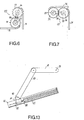
- the diameters of the two pinions being assumed to be equal, it can be seen that between the closed position of Fig. 6 and the extreme open position of FIG. 7, the plate 92 has practically rotated 180 °.
- Figs. 8 and 9 where the shafts 86 and 87 are respectively associated with the fixed upright 93 and mobile 94, illustrate how the mobile frame pivots relative to the fixed frame.
- the system 95 consists of two shafts 96 and 97 which are parallel to each other and to the axis of rotation of the system.
- the shaft 96 carries an axial pinion 98 which can rotate freely with respect to it, but which is integral with the link.
- the shaft 97 carries a pinion 99 of which it is integral.
- the shaft 97 can rotate in bearings which are connected to the pinion 98 by parts 100 serving as spacers. Sprockets 98 and 99 mesh.
- the tree 96 is secured to the amount 101 of the frame of a window with French sashes while the shaft 97 is secured to the amount 102 of the window sash.
- FIG. 10 shows the system 95 in the closed window position
- FIG. 11 shows it in the half-open window position
- FIG. 12 in the open position. It appears that starting from the closed position of FIG. 10, when the leaf 102 is rotated anti-clockwise, the axis 97 rotates with respect to the axis 96 in the clockwise direction. In fact, the rotation of the pinion 99, in the opposite direction, causes the pinion 98, free relative to 96, to rotate in the direct direction and the rotation of 98 causes that of the spacer 100 in the direct direction.
- the interval 105 between the outer edge 106 of 102 and the side of the rebate of 101 can be of the order of 1 mm.
- the seal 103 works in excellent conditions and, in particular, does not crash in the longitudinal direction.
- Fig. 13 a variant of the elastic means described in relation to FIGS. 1 and 2.
- the slide 111 has the shape of a small block which is housed and slides in a slide 112, formed by a U-shaped angle iron.
- the angle iron 112 is fixed on the internal face of the upright 57 , not shown, and is open up.
- the block of slide 111 is provided with a tapped hole into which is screwed a screw 113 which carries, at its end, an insert 114 which is housed in the end of the propeller of a spring 115.
- the other end of the spring 115 is fixed to the upper end of the slide 112.
- the spring 115 is a tension spring which is on the same side of the link 109 as the link 49.
- the materials of the slide 111 and of the slide 112, and their respective dimensions, are such that the slide acts as a brake in the slide.
- the spring 115 makes it easier to open the leaf, but, given the role of the slide brake, it cannot move it alone. It follows that, 'as soon as a leaf is given a position relative to the frame, it keeps it.
- hinge systems described in the present application can also be used for doors, French windows and other skylights, whatever the material of these.
Landscapes
- Engineering & Computer Science (AREA)
- Mechanical Engineering (AREA)
- Architecture (AREA)
- Civil Engineering (AREA)
- Structural Engineering (AREA)
- Wing Frames And Configurations (AREA)
- Closing And Opening Devices For Wings, And Checks For Wings (AREA)
- Springs (AREA)
- Transmission Devices (AREA)
Applications Claiming Priority (2)
| Application Number | Priority Date | Filing Date | Title |
|---|---|---|---|
| FR8115653 | 1981-08-06 | ||
| FR8115653A FR2511072B2 (fr) | 1981-08-06 | 1981-08-06 | Lucarne a rabattement |
Publications (2)
| Publication Number | Publication Date |
|---|---|
| EP0072320A2 true EP0072320A2 (de) | 1983-02-16 |
| EP0072320A3 EP0072320A3 (de) | 1983-07-06 |
Family
ID=9261432
Family Applications (1)
| Application Number | Title | Priority Date | Filing Date |
|---|---|---|---|
| EP82401475A Withdrawn EP0072320A3 (de) | 1981-08-06 | 1982-08-03 | Dachfenster in Schwenkflügelbauweise |
Country Status (2)
| Country | Link |
|---|---|
| EP (1) | EP0072320A3 (de) |
| FR (1) | FR2511072B2 (de) |
Cited By (3)
| Publication number | Priority date | Publication date | Assignee | Title |
|---|---|---|---|---|
| EP0846815A3 (de) * | 1996-12-04 | 1999-04-21 | ROTO FRANK Aktiengesellschaft | Dachfenster, insbesondere Schwingflügel-Dachfenster |
| EP0874103A3 (de) * | 1997-04-24 | 1999-06-09 | Dörken Tageslichtsysteme GmbH & Co Produktions KG | Schrägdach-Klappschwingfenster |
| US6493999B2 (en) * | 2001-01-19 | 2002-12-17 | Vkr Holding A/S | Roof window with an improved securing device |
Family Cites Families (12)
| Publication number | Priority date | Publication date | Assignee | Title |
|---|---|---|---|---|
| US2732966A (en) * | 1956-01-31 | Door operating mechanism | ||
| FR614006A (fr) * | 1926-01-28 | 1926-12-04 | Ferme-porte | |
| DE936077C (de) * | 1953-06-02 | 1955-12-01 | Mannesmann Stahlblechbau G M B | Kipptor, insbesondere fuer Garagen |
| US2715241A (en) * | 1953-11-17 | 1955-08-16 | Richard G Carlson | Combined door closer and retainer device |
| US2797838A (en) * | 1954-06-03 | 1957-07-02 | Leonard H Read | Closure stop |
| GB1265640A (de) * | 1971-02-04 | 1972-03-01 | ||
| US3838537A (en) * | 1973-07-02 | 1974-10-01 | Truth Inc | Window hinge |
| AT342275B (de) * | 1974-10-18 | 1978-03-28 | Josef Dipl Ing Schmidt | Dachflachenfenster |
| AT351226B (de) * | 1975-05-02 | 1979-07-10 | Waldner Fa Felix | Kipptor, insbesondere garagentor |
| IT1074926B (it) * | 1975-11-15 | 1985-04-22 | Blefa Ag | Portello finestra per tetti |
| GB1552917A (en) * | 1976-02-02 | 1979-09-19 | Bierlich J H | Window assemblies |
| DE2745192B2 (de) * | 1977-10-07 | 1980-11-06 | Reichstadt, Hans Udo, 4020 Mettmann | Wohndach-Fenster |
-
1981
- 1981-08-06 FR FR8115653A patent/FR2511072B2/fr not_active Expired - Lifetime
-
1982
- 1982-08-03 EP EP82401475A patent/EP0072320A3/de not_active Withdrawn
Cited By (3)
| Publication number | Priority date | Publication date | Assignee | Title |
|---|---|---|---|---|
| EP0846815A3 (de) * | 1996-12-04 | 1999-04-21 | ROTO FRANK Aktiengesellschaft | Dachfenster, insbesondere Schwingflügel-Dachfenster |
| EP0874103A3 (de) * | 1997-04-24 | 1999-06-09 | Dörken Tageslichtsysteme GmbH & Co Produktions KG | Schrägdach-Klappschwingfenster |
| US6493999B2 (en) * | 2001-01-19 | 2002-12-17 | Vkr Holding A/S | Roof window with an improved securing device |
Also Published As
| Publication number | Publication date |
|---|---|
| EP0072320A3 (de) | 1983-07-06 |
| FR2511072A2 (fr) | 1983-02-11 |
| FR2511072B2 (fr) | 1985-07-05 |
Similar Documents
| Publication | Publication Date | Title |
|---|---|---|
| EP0857844A1 (de) | Führungsvorrichtung für einen Öffnungsabschluss-Schwenk-Schiebeflügel | |
| FR2925567A1 (fr) | Dispositif d'obturation comportant au moins un obturateur symetrise repliable en accordeon | |
| FR3038632A1 (fr) | Lame orientable et isolante pour une installation de protection solaire | |
| WO2007096540A1 (fr) | Dispositif de montage articule d'une vitre sur une porte sans cadre de vehicule de type cabriolet ou coupe | |
| EP3401484B1 (de) | Gebäudeöffnungselemente wie türen oder fenster mit hebe- und schiebeflügel und stossdämpfungselement | |
| EP0072320A2 (de) | Dachfenster in Schwenkflügelbauweise | |
| EP0041875A1 (de) | Profilleisten aus Kunststoff für Vorsatzfensterrahmen | |
| EP1140535A1 (de) | Sicherheitsvorrichtung mit glasöffnung mit beweglichem verschluss | |
| EP2118418B1 (de) | Scharniersystem für ein sektionaltor, sektionaltor und befestigungsverfahren dafür | |
| EP1865224B1 (de) | Schliessvorrichtung mit System oder Vorrichtung zur Übertragung einer Drehbewegung eines ersten Gegenstands um eine erste Achse auf einen zweiten Gegenstand um eine zweite Achse | |
| FR2488322A1 (fr) | Lucarne a rabattement | |
| EP0345186B1 (de) | Feststeller für italienische, australische und mit Scharnieren versehene Fenster o.dgl. | |
| FR2768767A1 (fr) | Persienne coulissante a charniere | |
| FR2469540A1 (fr) | Fenetre a projection a un ou plusieurs chassis, a retournement | |
| EP0085632A1 (de) | Dachfenster | |
| EP2080868B1 (de) | Schiebetür- oder Fensterflügel, insbesondere vom Typ Rollladen | |
| FR2717213A1 (fr) | Dispositif perfectionné d'articulation d'un ouvrant, notamment d'un hayon arrière de véhicule automobile. | |
| EP0143722B1 (de) | Kraftfahrzeugtür mit Schiebefenster | |
| FR2553347A1 (fr) | Porte d'acces pour vehicule de transport en commun | |
| EP4093937A1 (de) | Reversibel verriegelbares gelenk und fahrzeugfenster mit einem solchen gelenk | |
| FR2509363A1 (fr) | Dispositif d'occultation a lames paralleles coulissantes et orientables a commande electro-mecanique pour baies vitrees verticales, horizontales ou inclinees de grandes dimensions | |
| FR3154426A1 (fr) | : Blocage porte en position ouverte | |
| FR2788807A1 (fr) | Element de fermeture | |
| EP3180486A1 (de) | Taschenartige öffnungsplatte mit horizontal gelenkigen schwenkbaren klappen | |
| CA2271985A1 (fr) | Dispositif de manoeuvre de jalousies a effort assiste |
Legal Events
| Date | Code | Title | Description |
|---|---|---|---|
| PUAI | Public reference made under article 153(3) epc to a published international application that has entered the european phase |
Free format text: ORIGINAL CODE: 0009012 |
|
| AK | Designated contracting states |
Designated state(s): AT BE CH DE FR GB IT LI LU NL SE |
|
| PUAL | Search report despatched |
Free format text: ORIGINAL CODE: 0009013 |
|
| AK | Designated contracting states |
Designated state(s): AT BE CH DE FR GB IT LI LU NL SE |
|
| STAA | Information on the status of an ep patent application or granted ep patent |
Free format text: STATUS: THE APPLICATION IS DEEMED TO BE WITHDRAWN |
|
| 18D | Application deemed to be withdrawn |
Effective date: 19840307 |