EP0072402A2 - Procédé et dispositif pour éliminer ou diminuer l'excentricité à la jonction de bouts opposés de tubes par soudage - Google Patents
Procédé et dispositif pour éliminer ou diminuer l'excentricité à la jonction de bouts opposés de tubes par soudage Download PDFInfo
- Publication number
- EP0072402A2 EP0072402A2 EP82105445A EP82105445A EP0072402A2 EP 0072402 A2 EP0072402 A2 EP 0072402A2 EP 82105445 A EP82105445 A EP 82105445A EP 82105445 A EP82105445 A EP 82105445A EP 0072402 A2 EP0072402 A2 EP 0072402A2
- Authority
- EP
- European Patent Office
- Prior art keywords
- pipe
- pipe part
- hollow cylinder
- mandrel
- recess
- Prior art date
- Legal status (The legal status is an assumption and is not a legal conclusion. Google has not performed a legal analysis and makes no representation as to the accuracy of the status listed.)
- Granted
Links
Images
Classifications
-
- B—PERFORMING OPERATIONS; TRANSPORTING
- B23—MACHINE TOOLS; METAL-WORKING NOT OTHERWISE PROVIDED FOR
- B23K—SOLDERING OR UNSOLDERING; WELDING; CLADDING OR PLATING BY SOLDERING OR WELDING; CUTTING BY APPLYING HEAT LOCALLY, e.g. FLAME CUTTING; WORKING BY LASER BEAM
- B23K33/00—Specially-profiled edge portions of workpieces for making soldering or welding connections; Filling the seams formed thereby
- B23K33/004—Filling of continuous seams
- B23K33/006—Filling of continuous seams for cylindrical workpieces
-
- B—PERFORMING OPERATIONS; TRANSPORTING
- B29—WORKING OF PLASTICS; WORKING OF SUBSTANCES IN A PLASTIC STATE IN GENERAL
- B29C—SHAPING OR JOINING OF PLASTICS; SHAPING OF MATERIAL IN A PLASTIC STATE, NOT OTHERWISE PROVIDED FOR; AFTER-TREATMENT OF THE SHAPED PRODUCTS, e.g. REPAIRING
- B29C66/00—General aspects of processes or apparatus for joining preformed parts
- B29C66/01—General aspects dealing with the joint area or with the area to be joined
- B29C66/02—Preparation of the material, in the area to be joined, prior to joining or welding
- B29C66/022—Mechanical pre-treatments, e.g. reshaping
Definitions
- the invention relates to a method and a device for eliminating or reducing the edge misalignment when connecting pipe bodies or pipe parts over mutually opposite ends with the aid of a weld seam.
- deviations in shape which may be caused by them, for example, or may be increased in addition to the deviations in shape as a result of the tolerances customary in the trade in that the pipe part has been subjected to a compression molding process in its longitudinal direction from the ends for deformation purposes.
- Such deviations require an edge offset and an elaborate mechanical processing at the ends of the spool to be produced. in order to correct the discrepancies caused by the edge offset.
- the invention essentially aims to eliminate the aforementioned disadvantages.
- the method for this according to the invention essentially avoids the disadvantageous edge offset in that, when pressure is exerted on the tubular body or the pipeline part in the longitudinal direction, one end of the tubular body or the pipeline part is pushed onto a calibration mandrel and at the same time in a hollow cylinder surrounding the calibrating mandrel with a the inner diameter corresponding to the outer diameter of the pipe body or the pipe part and pressed with the end dipping into the hollow cylinder under pressure to bear against the bottom of the hollow cylinder in order to deform the end face edge of the pipe body or the pipe part in accordance with a desired or required shape of the Weld is brought.
- the pipe part can be brought to a temperature suitable for the material, taking into account the deformation work to be performed.
- the inventive method ensures that inaccuracies, in particular out-of-roundness of the tube, for. B. due to the commercial tolerances, serf, so that between the parts to be connected only a small edge offset can occur, which is required above all in power plant construction.
- Another advantage of the pressed welding edges - is that gradually thickening occurs on these pipe ends treated or prepared in this way, which allows any mechanical processing after the welding process, without causing the risk of the wall thickness being less than that. This fact helps with the ultrasonic testing for longitudinal and Cross errors to favorable results.
- the method can expediently be combined or combined with a compression upsetting of the pipeline part or a straight pipeline part by applying pressure in the longitudinal direction of the pipeline part.
- Compression upsetting can be carried out, for example, to create bends. For elbows to form in a pipe or in a pipe part by thickening.
- a device for carrying out the method is characterized in that in a press or pressure ram which is intended to act on an end face of the tubular body or the pipeline part in its longitudinal direction or longitudinal axis in a recess on the side facing the workpiece with a through the Outside diameter of the pipe part, the inside diameter for receiving the end of the pipe part is provided with a calibration mandrel of an outside diameter corresponding to the inside diameter of the pipe part for engagement in the end of the pipe body or the end of the pipe part, and that the bottom ring surface between the mandrel and the hollow cylinder or the recess wall has a shape corresponding to a desired weld.
- the calibration dome can expediently protrude from the recess surrounding it and from the end face of the press and pressure stamp. This facilitates the plugging of the pipe part on the calibration dome and the introduction of the pipe part into the recess of the pressure stamp.
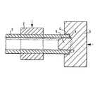
- the drawing schematically illustrates an embodiment of the device according to the invention for carrying out the method according to the invention.
- the part of the pipeline which is to be subjected, for example, to deformation by compression molding in the longitudinal direction, is designated by 1. It is clamped between hydraulically operated jaws 2. In the longitudinal direction of the clamped pipe part 1, the pressure or press ram 3 is provided.
- a recess 4 is provided in the form of a hollow cylinder which is axially identical to the press die and the pipeline part and which has an inside diameter which is the same as the outside diameter of the workpiece 1 or approximately the same while leaving some play.
- the calibration mandrel 5 is located in the recess or the hollow cylinder on the press ram, the outside diameter of which is determined by the inside diameter of the pipe part 1. The mandrel protrudes from the punch 3.
- the bottom 6 of the recess 4 has a shape due to the weld seam to be drawn, in the present case the shape of a half tulip stem for a tulip weld seam.
- Both mutually facing pipe ends at a connection point can be subjected to the treatment according to the invention.
- the workpiece is compressed in the ! Heat, ie when the workpiece is heated to the deformation temperature.
Landscapes
- Engineering & Computer Science (AREA)
- Mechanical Engineering (AREA)
- Butt Welding And Welding Of Specific Article (AREA)
- Forging (AREA)
- Pressure Welding/Diffusion-Bonding (AREA)
- Rigid Containers With Two Or More Constituent Elements (AREA)
- Shaping Of Tube Ends By Bending Or Straightening (AREA)
Priority Applications (1)
| Application Number | Priority Date | Filing Date | Title |
|---|---|---|---|
| AT82105445T ATE18644T1 (de) | 1981-06-27 | 1982-06-22 | Verfahren und vorrichtung zum beheben bzw. verringern des kantenversatzes bei der verbindung von rohrkoerpern ueber sich gegenueberstehende stirnenden durch schweissen. |
Applications Claiming Priority (2)
| Application Number | Priority Date | Filing Date | Title |
|---|---|---|---|
| DE3125435 | 1981-06-27 | ||
| DE3125435A DE3125435C1 (de) | 1981-06-27 | 1981-06-27 | Verfahren und Vorrichtung zum Beheben bzw. Verringern des Kantenversatzes bei der Verbindung von Rohrkoerpern ueber sich gegenueberstehende Stirnenden durch Schweissen |
Publications (3)
| Publication Number | Publication Date |
|---|---|
| EP0072402A2 true EP0072402A2 (fr) | 1983-02-23 |
| EP0072402A3 EP0072402A3 (en) | 1983-09-21 |
| EP0072402B1 EP0072402B1 (fr) | 1986-03-19 |
Family
ID=6135577
Family Applications (1)
| Application Number | Title | Priority Date | Filing Date |
|---|---|---|---|
| EP82105445A Expired EP0072402B1 (fr) | 1981-06-27 | 1982-06-22 | Procédé et dispositif pour éliminer ou diminuer l'excentricité à la jonction de bouts opposés de tubes par soudage |
Country Status (5)
| Country | Link |
|---|---|
| EP (1) | EP0072402B1 (fr) |
| JP (2) | JPS5850132A (fr) |
| AT (1) | ATE18644T1 (fr) |
| DE (1) | DE3125435C1 (fr) |
| ZA (1) | ZA824591B (fr) |
Family Cites Families (4)
| Publication number | Priority date | Publication date | Assignee | Title |
|---|---|---|---|---|
| FR695339A (fr) * | 1930-05-08 | 1930-12-13 | Procédé d'assemblage par soudure pour tuyaux métalliques | |
| GB1201693A (en) * | 1967-09-01 | 1970-08-12 | Kocks Wermelskirchen G M B H | Apparatus for calibrating pipes |
| US3594894A (en) * | 1968-11-20 | 1971-07-27 | Gen Fire Extinguisher Corp | Method of forming cartridges |
| US3752348A (en) * | 1971-08-30 | 1973-08-14 | Ford Motor Co | Motor vehicle electrically heated windshield and backlight system |
-
1981
- 1981-06-27 DE DE3125435A patent/DE3125435C1/de not_active Expired
-
1982
- 1982-06-22 AT AT82105445T patent/ATE18644T1/de not_active IP Right Cessation
- 1982-06-22 EP EP82105445A patent/EP0072402B1/fr not_active Expired
- 1982-06-28 JP JP57110048A patent/JPS5850132A/ja active Pending
- 1982-06-28 ZA ZA824591A patent/ZA824591B/xx unknown
-
1984
- 1984-09-28 JP JP1984145808U patent/JPS60103521U/ja active Pending
Also Published As
| Publication number | Publication date |
|---|---|
| JPS60103521U (ja) | 1985-07-15 |
| EP0072402A3 (en) | 1983-09-21 |
| ZA824591B (en) | 1983-10-26 |
| EP0072402B1 (fr) | 1986-03-19 |
| DE3125435C1 (de) | 1983-05-19 |
| JPS5850132A (ja) | 1983-03-24 |
| ATE18644T1 (de) | 1986-04-15 |
Similar Documents
| Publication | Publication Date | Title |
|---|---|---|
| EP0523215B1 (fr) | Procede et dispositif de formage hydrostatique de corps creux en metal deformable a froid | |
| DE2657269B2 (de) | Verfahren zur Herstellung von Stahlrohren | |
| DE3226868C2 (fr) | ||
| DE3001666A1 (de) | Gewelltes leitungsrohr aus nichtrostendem stahl und verfahren zur herstellung desselben | |
| DE4337517A1 (de) | Verfahren zum Innenhochdruck-Umformen von hohlen abgesetzten Wellen aus kaltumformbarem Metall | |
| DE19520099C2 (de) | Rohrverbindung und Verfahren zu ihrer Herstellung | |
| EP1707861B1 (fr) | Raccord et son procédé de fabrication | |
| DE2818671A1 (de) | Verfahren zur entspannung eines mechanisch eingewalzten rohrs | |
| DE4322711C2 (de) | Verfahren zum Herstellen eines Rohrbogens | |
| EP2205371B1 (fr) | Procédé pour fabriquer des systèmes à double tube | |
| DE69322965T2 (de) | Verfahren zur herstellung von rohrförmigen elementen mit integralen äusserlichen vorsprüngen | |
| DE19757946C2 (de) | Rohrverbindung | |
| EP0072402A2 (fr) | Procédé et dispositif pour éliminer ou diminuer l'excentricité à la jonction de bouts opposés de tubes par soudage | |
| DE532919C (de) | Herstellung von Rohren mit nach innen verstaerkten Enden durch Stauchen | |
| DE102011107450A1 (de) | Vorrichtung und Verfahren zum Umformen eines Rohrs | |
| EP0441174A2 (fr) | Procédé et outil de formage pour refouler un nipple | |
| DE906164C (de) | Nicht loesbare Verbindung zwischen einem Rohr und einem anderen Koerper und Verfahren zur Herstellung der Verbindung | |
| EP0070406A2 (fr) | Procédé de fabrication d'un tronçon de conduite tubulaire comportant au moins un coude placé entre des parties de tube droites | |
| DE1261102B (de) | Verfahren und Vorrichtung zum Herstellen von Rohrbogen mit sich vom einen zum anderen Ende gleichmaessig verjuengendem Querschnitt | |
| DE10061635A1 (de) | Umform- und Fügeverfahren von zumindest zwei Bauteilen und Vorrichtung | |
| DE3633959C1 (en) | Method for the production of a tube end with a connection | |
| DE19854044C1 (de) | Verfahren zum Verbinden eines Rohres mit einem Fitting sowie Kombination aus Fitting, Rohr und Preßgerät zur Durchführung des Verfahrens | |
| DE1627788B1 (de) | Verfahren zum herstellen eines zylindrischen stabes aus stahl mit einem aufplattierten rohrförmigen mantel aus stahl anderer chemischer zusammensetzung | |
| DE4329540C1 (de) | Vorrichtung zum Kalibrieren gebogener Rohrstücke mit im wesentlichen kreisförmigem Querschnitt | |
| DE654108C (de) | Verfahren zum Herstellen von gebogenen Rohren mit kreisfoermigem Querschnitt |
Legal Events
| Date | Code | Title | Description |
|---|---|---|---|
| PUAI | Public reference made under article 153(3) epc to a published international application that has entered the european phase |
Free format text: ORIGINAL CODE: 0009012 |
|
| AK | Designated contracting states |
Designated state(s): AT BE CH FR GB IT LI LU NL SE |
|
| 17P | Request for examination filed |
Effective date: 19830121 |
|
| PUAL | Search report despatched |
Free format text: ORIGINAL CODE: 0009013 |
|
| AK | Designated contracting states |
Designated state(s): AT BE CH FR GB IT LI LU NL SE |
|
| RAP1 | Party data changed (applicant data changed or rights of an application transferred) |
Owner name: EMIL WOLFF MASCHINENFABRIK UND EISENGIESSEREI GMBH |
|
| GRAA | (expected) grant |
Free format text: ORIGINAL CODE: 0009210 |
|
| AK | Designated contracting states |
Kind code of ref document: B1 Designated state(s): AT BE CH FR GB IT LI LU NL SE |
|
| PG25 | Lapsed in a contracting state [announced via postgrant information from national office to epo] |
Ref country code: NL Effective date: 19860319 Ref country code: IT Free format text: LAPSE BECAUSE OF FAILURE TO SUBMIT A TRANSLATION OF THE DESCRIPTION OR TO PAY THE FEE WITHIN THE PRESCRIBED TIME-LIMIT;WARNING: LAPSES OF ITALIAN PATENTS WITH EFFECTIVE DATE BEFORE 2007 MAY HAVE OCCURRED AT ANY TIME BEFORE 2007. THE CORRECT EFFECTIVE DATE MAY BE DIFFERENT FROM THE ONE RECORDED. Effective date: 19860319 Ref country code: FR Free format text: THE PATENT HAS BEEN ANNULLED BY A DECISION OF A NATIONAL AUTHORITY Effective date: 19860319 Ref country code: BE Effective date: 19860319 |
|
| REF | Corresponds to: |
Ref document number: 18644 Country of ref document: AT Date of ref document: 19860415 Kind code of ref document: T |
|
| PG25 | Lapsed in a contracting state [announced via postgrant information from national office to epo] |
Ref country code: SE Effective date: 19860331 |
|
| PG25 | Lapsed in a contracting state [announced via postgrant information from national office to epo] |
Ref country code: AT Effective date: 19860622 |
|
| PG25 | Lapsed in a contracting state [announced via postgrant information from national office to epo] |
Ref country code: LU Free format text: LAPSE BECAUSE OF NON-PAYMENT OF DUE FEES Effective date: 19860630 Ref country code: LI Effective date: 19860630 Ref country code: CH Effective date: 19860630 |
|
| EN | Fr: translation not filed | ||
| NLV1 | Nl: lapsed or annulled due to failure to fulfill the requirements of art. 29p and 29m of the patents act | ||
| PLBE | No opposition filed within time limit |
Free format text: ORIGINAL CODE: 0009261 |
|
| STAA | Information on the status of an ep patent application or granted ep patent |
Free format text: STATUS: NO OPPOSITION FILED WITHIN TIME LIMIT |
|
| REG | Reference to a national code |
Ref country code: CH Ref legal event code: PL |
|
| 26N | No opposition filed | ||
| PG25 | Lapsed in a contracting state [announced via postgrant information from national office to epo] |
Ref country code: GB Effective date: 19880622 |
|
| GBPC | Gb: european patent ceased through non-payment of renewal fee |