EP0072417B1 - Dispositif électrique, en particulier dispositif de clôture électrique ayant une enveloppe étanche au jet d'eau - Google Patents
Dispositif électrique, en particulier dispositif de clôture électrique ayant une enveloppe étanche au jet d'eau Download PDFInfo
- Publication number
- EP0072417B1 EP0072417B1 EP82105803A EP82105803A EP0072417B1 EP 0072417 B1 EP0072417 B1 EP 0072417B1 EP 82105803 A EP82105803 A EP 82105803A EP 82105803 A EP82105803 A EP 82105803A EP 0072417 B1 EP0072417 B1 EP 0072417B1
- Authority
- EP
- European Patent Office
- Prior art keywords
- casing part
- upper casing
- peripheral wall
- closure
- wall
- Prior art date
- Legal status (The legal status is an assumption and is not a legal conclusion. Google has not performed a legal analysis and makes no representation as to the accuracy of the status listed.)
- Expired
Links
- 230000002093 peripheral effect Effects 0.000 claims abstract description 66
- 238000007789 sealing Methods 0.000 claims abstract description 6
- 239000000872 buffer Substances 0.000 claims description 21
- 238000012360 testing method Methods 0.000 claims description 17
- XLYOFNOQVPJJNP-UHFFFAOYSA-N water Substances O XLYOFNOQVPJJNP-UHFFFAOYSA-N 0.000 claims description 12
- 230000015572 biosynthetic process Effects 0.000 claims description 10
- 238000005755 formation reaction Methods 0.000 claims description 10
- 230000009471 action Effects 0.000 claims description 2
- 210000001331 nose Anatomy 0.000 claims 2
- 230000002349 favourable effect Effects 0.000 description 6
- 238000011161 development Methods 0.000 description 4
- 230000018109 developmental process Effects 0.000 description 4
- 230000006872 improvement Effects 0.000 description 4
- 238000013461 design Methods 0.000 description 3
- 238000000034 method Methods 0.000 description 3
- 230000000087 stabilizing effect Effects 0.000 description 3
- 230000002411 adverse Effects 0.000 description 2
- QVGXLLKOCUKJST-UHFFFAOYSA-N atomic oxygen Chemical compound [O] QVGXLLKOCUKJST-UHFFFAOYSA-N 0.000 description 2
- 238000010276 construction Methods 0.000 description 2
- 230000002950 deficient Effects 0.000 description 2
- 238000009826 distribution Methods 0.000 description 2
- 230000014759 maintenance of location Effects 0.000 description 2
- 238000004519 manufacturing process Methods 0.000 description 2
- 229910052760 oxygen Inorganic materials 0.000 description 2
- 239000001301 oxygen Substances 0.000 description 2
- 230000000149 penetrating effect Effects 0.000 description 2
- 230000008569 process Effects 0.000 description 2
- 230000000717 retained effect Effects 0.000 description 2
- 238000003860 storage Methods 0.000 description 2
- 241000283690 Bos taurus Species 0.000 description 1
- 206010039203 Road traffic accident Diseases 0.000 description 1
- 230000004308 accommodation Effects 0.000 description 1
- 238000005452 bending Methods 0.000 description 1
- 230000008901 benefit Effects 0.000 description 1
- 230000008859 change Effects 0.000 description 1
- 230000008602 contraction Effects 0.000 description 1
- 230000007547 defect Effects 0.000 description 1
- 238000006073 displacement reaction Methods 0.000 description 1
- 230000000694 effects Effects 0.000 description 1
- 239000006260 foam Substances 0.000 description 1
- 239000011521 glass Substances 0.000 description 1
- 238000003780 insertion Methods 0.000 description 1
- 230000037431 insertion Effects 0.000 description 1
- 239000002184 metal Substances 0.000 description 1
- 238000009740 moulding (composite fabrication) Methods 0.000 description 1
- 239000012188 paraffin wax Substances 0.000 description 1
- 230000001105 regulatory effect Effects 0.000 description 1
- 238000000926 separation method Methods 0.000 description 1
- 239000003381 stabilizer Substances 0.000 description 1
- 238000012549 training Methods 0.000 description 1
- 230000007704 transition Effects 0.000 description 1
- 238000009423 ventilation Methods 0.000 description 1
Images





Classifications
-
- H—ELECTRICITY
- H05—ELECTRIC TECHNIQUES NOT OTHERWISE PROVIDED FOR
- H05K—PRINTED CIRCUITS; CASINGS OR CONSTRUCTIONAL DETAILS OF ELECTRIC APPARATUS; MANUFACTURE OF ASSEMBLAGES OF ELECTRICAL COMPONENTS
- H05K5/00—Casings, cabinets or drawers for electric apparatus
- H05K5/06—Hermetically-sealed casings
- H05K5/063—Hermetically-sealed casings sealed by a labyrinth structure provided at the joining parts
-
- H—ELECTRICITY
- H05—ELECTRIC TECHNIQUES NOT OTHERWISE PROVIDED FOR
- H05C—ELECTRIC CIRCUITS OR APPARATUS SPECIALLY DESIGNED FOR USE IN EQUIPMENT FOR KILLING, STUNNING, OR GUIDING LIVING BEINGS
- H05C1/00—Circuits or apparatus for generating electric shock effects
Definitions
- the invention relates to electrical devices which can be set up outdoors and are protected against the ingress of splashing water, preferably electric fencing devices, the housings for the joint accommodation of a power source, for example a dry battery, and an electrical circuit arrangement, a container-like housing lower part for accommodating the power source and a substantially lid-like one Has upper housing part for receiving the electrical circuit parts, the lower housing part in a strip-shaped area of its opening edge all overlaps with a flange-like peripheral wall part provided on the upper housing part and closure elements are attached to the outside of the lower housing part and the upper housing part.
- a power source for example a dry battery
- an electrical circuit arrangement a container-like housing lower part for accommodating the power source and a substantially lid-like one
- Has upper housing part for receiving the electrical circuit parts
- the lower housing part in a strip-shaped area of its opening edge all overlaps with a flange-like peripheral wall part provided on the upper housing part and closure elements are attached to the outside of the lower housing part and the upper housing part.
- both the upper housing part and the lower housing part are provided with an outwardly extending flange at their opening edge. These flanges are to be placed on top of one another and fastened to one another by means of closure elements attached thereto in the manner of screw closures.
- a certain splash protection of this flange connection is formed in that the flange carries at the opening edge of the upper housing part an additional, all-round strip-shaped wall part which axially engages over the flange of the lower housing part on the outside.
- this known device has the defect that screwed connections that have to be tightened in order to replace the power source have to be loosened before the upper housing part can be removed and the battery can be replaced.
- hinge connections are provided between the lower housing part and the upper housing part.
- all known device housings of the type mentioned above be it with a screw connection or hinge connection between the upper part of the device and the lower part of the device, the separation of the two housing parts is only to be carried out in a relatively cumbersome manner, and there is a risk that loose connecting elements which are to be removed for separating the housing parts can easily be removed be lost. Since such devices are set up outdoors, there is often only a provisional connection of the housing parts with the risk of the complete failure of the device, in particular if connection parts are lost.
- the user of electric fence devices has a high duty of care, because if cattle break out due to defective electric fence systems, serious traffic accidents can occur or other significant damage can be caused.
- the device housing should be free of corrosion-prone parts and provide the device with optimal protection against adverse external influences, e.g. weather protection, and keep the device parts splash-proof, whereby at least parts of the device interior should be able to exchange with the atmospheric air.
- closure elements as the lower closure strips extending parallel to the opening edge of the lower housing part and the upper closure strips extending parallel to the lower edge of the upper housing part, which sit on the lower closure strips when the housing is assembled, and in each case one on top of the other
- a pair of lower and upper locking strips are inserted, provided with anti-pull-off locking clips, and that the flange-like peripheral wall part of the housing upper part engages as a splash-proof seal in the opening edge of the lower housing part and has leading, labyrinth-like air inlets into the interior of the lower housing part.
- the closure achieved by the sliding closure elements with locking clip in connection with the overlapping edge parts of the lower housing part and upper housing part can be operated without a screw or other locking means and is therefore easy to open and close, the overlapping, interlocking edge parts of the lower housing part and upper housing part not only prevent mutual displacement of the housing parts, but also offer favorable guidance when assembling and disassembling the housing parts.
- the axially acting wedge connection achieved with the sliding locking elements and the locking clip is safer and more stable than conventional hinge connections.
- the force distribution when carrying the device is optimal.
- the design of the bushings for moving parts, such as switches and control and test devices of the device not only enables the arrangement of these parts in the most convenient and convenient place for operating the device, but also the attachment of such switches or control or test devices directly to circuit modules .
- the upper housing part can preferably be designed in the manner of a slip lid with a peripheral wall and a lower opening edge and the peripheral wall part overlapping with the opening edge region of the lower housing part can be the peripheral wall of an intermediate floor, the peripheral wall of the intermediate floor being designed to match the opening cross section of the lower housing part and the opening cross section of the upper housing part and devices for locking in the upper part in such a position in which the peripheral wall of the intermediate floor protrudes axially relative to the peripheral edge of the upper housing part.
- the upper housing part becomes, in a particularly favorable manner, a practically all-round closed partial housing which can be placed on the lower housing part and which receives the electrical circuit parts and is sealed off from the interior of the lower housing part receiving the power source.
- the intermediate floor forms a stabilizing element in the interior of the entire housing, in particular in the interior of the housing upper part.
- the peripheral wall of the intermediate floor protruding from above into the lower part of the housing surrounds the upper edge of the battery used in the lower part of the housing, so that the battery is protected against splashing water, even if the lower part of the housing is correspondingly wide for simple, easy insertion and removal of the battery is trained.
- the sliding closure elements are designed as wedge closure strips projecting laterally on the housing parts.
- the sliding closure can be easily contracted between the two housing parts with particularly easy actuation.
- the upper housing part and the lower housing part can each carry wedge locking strips as halves of one or more wedges, each of which forms a complete wedge when the two housing parts are assembled in the correct direction, with a locking clip designed as a wedge sleeve being pulled over this wedge. This ensures that the locking clip only engages positively over the wedge formed from two wedge locking strips when the two housing parts are assembled in the correct direction. This provides a simple safeguard against incorrect assembly of the housing parts.
- the wedge closure strips can preferably be molded into the wall of the upper housing part and the wall of the lower housing part, while suitable projections are formed in the peripheral wall of the intermediate floor in the rear wall formations formed by these wedge closure strips.
- These projections of the peripheral wall on the intermediate floor also form precisely fitting sealing connecting elements between the walls of the housing parts and the peripheral wall of the intermediate floor in the area of the wedge-type sealing strips.
- these projections on the circumferential wall of the intermediate floor only fit into the corresponding wall formings when the housing parts are assembled in the right direction.
- the peripheral wall of the intermediate floor has a predetermined height, for example substantially the middle height, an outwardly projecting flange which lies flush between the end faces of the walls of the lower housing part and the upper housing part.
- this flange precisely defines the position of the intermediate floor, in particular with respect to the upper housing part.
- mutual wedging of the firmly contracted housing parts is prevented.
- the flange offers an advantageous additional seal for the closed housing.
- the anti-pull-off device of the locking clip can be a snap hook attached to it and engaging behind correspondingly projecting parts on the housing when the slide locking elements are fully opened.
- a snap hook can be actuated simply and securely and can be attached or trained in a simple manner on the locking clip.
- a pair of wedge-locking elements can be arranged on two opposite wall regions of the housing be, and two locking clips can be connected to each other via a bracket, which is designed as a handle extending at a distance over the upper part of the device.
- the battery usually has a weight of approx. 3 kg and is by far the heaviest part of the whole device.
- the handle is attached to the upper part, whereby the flow of force runs through the wall of the upper housing part and the hinge connection to the lower housing part.
- the latching of the intermediate floor in the upper housing part can take place in an advantageous development of the invention in that at the top of at least two opposite areas of the intermediate floor peripheral wall outwardly projecting horizontal ribs or lugs and corresponding receiving openings are formed in the corresponding wall regions of the upper housing part.
- These ribs or lugs engage in the corresponding receptacles in the wall of the upper housing part and thus form a secure snap-in connection, which ensures that the intermediate floor always remains connected to the upper housing part when the device is opened, the interior of the upper housing part containing the electrical circuit parts only through Loosen this secure snap connection, d. H. can be opened intentionally.
- ventilation is provided which is safe against the ingress of moisture and rain.
- vertical grooves leading into the interior of the lower housing part can be formed on the peripheral wall of the intermediate floor, for example in the area below the horizontal ribs or lugs.
- peripheral wall of the intermediate floor has an outwardly projecting flange, this will be interrupted in the area of the vertical grooves.
- the intermediate floor which acts as a stabilizing element, can be equipped with buffer elements.
- the intermediate floor can carry buffer elements on its underside, which are supported on the power source.
- the intermediate floor can also carry buffer elements on the top, which sit against the electrical circuit parts accommodated in the upper housing part. It can be provided that the electrical circuit arrangement is applied in the form of a plurality of circuit modules with plug connections and the buffer elements attached to the top of the intermediate base are designed as holding devices for holding the circuit modules plugged together.
- the electrical circuit arrangement preferably contains at least one circuit module inserted into the upper part of the housing, to which at least one externally actuable switch and / or one externally operable control or testing device is attached directly and with his or her actuating part carrying the operating element a labyrinth seal splash-proof protrudes on the outside of the upper part of the housing.
- the direct attachment of such switches or control or test devices on one or the other circuit module not only makes the manufacture of the electrical circuit arrangement of the device cheaper, but also offers the easy, quick interchangeability of such circuit parts, which often wear out most quickly when actuated, together with the corresponding module plate .
- this preferred embodiment offers the possibility of arranging the operating elements of such switches and regulating or testing devices at a particularly favorable location on the upper housing part.
- the operating element can be a pushbutton or rotary knob designed with an end wall and peripheral wall and a central, rear connecting shaft, the periphery of which is movably attached in a receptacle designed as a depression on the upper housing part, preferably its peripheral wall.
- the control element forms a practically smooth seal with the wall surface of the upper housing part. It then remains. only a narrow slot, necessary for the mobility of the push or turn button, through which rainwater does not and splash water can only penetrate in a negligible amount. However, this small amount of water is surely retained by the labyrinth seal and cannot penetrate into the interior of the upper part of the housing.
- the labyrinth seal can be formed by a labyrinth bushing provided in the bottom wall of the receptacle and overlapping with the peripheral wall of the push button or rotary knob, which receives the actuating part of the switch or the control or test element and the connecting shaft of the push button or rotary knob.
- the receptacle designed as a recess in the wall, preferably the peripheral wall, of the upper housing part can have a water drainage leading to the outside of the housing.
- Additional protection of the electrical circuit arrangement against moisture can preferably be achieved in that the circuit parts accommodated in the upper housing part, in particular circuit modules, have moisture protection. Since the labyrinth seal allows the entry of fog or moist air into the interior of the upper part of the housing, If the temperature fluctuates, it could happen that circuit parts fog up with moisture. Such moisture protection, for example a paraffin layer or the like, makes the circuit parts insensitive to such fogging with moisture.
- the electrical connection terminals can preferably be arranged in depressions formed on the upper housing part.
- the receptacle for the operating elements for electrical switches and / or control and test devices are arranged on one end of the upper housing part directly below the top wall thereof and the troughs receiving the connection terminals are formed in the upper corner areas of the opposite end side of the upper part of the housing.
- a further improvement for the splash-proof storage of the power source in the device and the easy interchangeability of the power source results in a preferred embodiment of the invention in that the lower part of the device - possibly by means of additional inserts - is designed so that an inserted power source is always in the inside of the peripheral wall part protrudes cavity formed on the upper housing part.
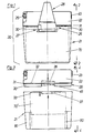
- the device housing 20 has a container-like housing lower part 21, in the interior of which the power source required for the operation of the electric fence device, in particular a dry battery, is to be accommodated.
- a lid-like upper device part 22 is placed, which - as the drawing shows - has sufficient height to be able to accommodate the electrical circuit parts of the energizer in its interior.
- Figures 1 to 6 accordingly show the operating buttons 23 (on-off switch and battery test) as well as control lamps 24, 68 and terminals 25 for the electric fence.
- the lower housing part 21 and the upper housing part 22 are held together by a slide closure 26, which is equipped with a pull-off protection 27 and at the same time is combined with the handle 28 of the device housing 20.
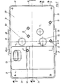
- the device housing 20 is also equipped with an intermediate base 29 (see FIGS. 7 to 12), which has an outwardly projecting flange 31 formed on its peripheral wall 30 between the opening-side end faces 32 and 33 on the peripheral walls of the lower housing part 21 and the upper housing part 22 engages and is flush with the outer surface of the device housing 20, so that there is a substantially smooth transition from the outer surface of the upper housing part 22 to the outer surface of the lower housing part 21 and thereby rainwater flows freely, without moisture penetrating into the interior of the device housing.
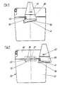
- This is ensured in connection with the peripheral wall 30 of the intermediate floor 29, which can only be seen in FIGS. 3 and 4 with its lower part projecting into the lower housing part 21, while FIGS. 8 to 12 show that the peripheral wall 30 of the intermediate floor 29 has, for example, an equally wide area above the flange 31 and fits into the opening of the upper housing part 22 with this upper part.
- the intermediate base 29 remains in the upper housing part 22 when the device housing is opened, because it carries a rib 34 on each narrow side of its peripheral wall 30, which rib engages in a corresponding horizontal slot 35 in the narrow sides of the peripheral wall of the upper housing part 22 (see Figure 4).
- the locking takes place by that both the upper housing part 22 and the intermediate base 29 are molded from plastic and accordingly have elastic resilience.
- the lower housing part can also be made of plastic. However, production from light metal or the like is also possible for the lower housing part 21.
- the elements of the slide closure 26 attached to the outside of the lower housing part 21 and the upper housing part 22 are formed by wedge locking strips 36 which are formed on the lower edge of the central side wall regions of the upper housing part 22 and by wedge locking strips 37 which are formed on the upper edge of the central side wall regions of the lower housing part 21 are integrally formed and - as FIG. 6 shows - lie exactly opposite one another when the lower housing part 21 and upper housing part 22 are correctly assembled, in order to form a wedge on each side wall, via which a locking clip 38 is to be pulled open.
- the wedge formed by the wedge locking strips 36 and 37 has a cross-section which widens outward in the manner of a dovetail, so that a lateral pulling off of the locking clip 38 is made impossible.
- the flange 31 on the peripheral wall 30 of the intermediate base 29 extends continuously through the area of the wedge locking strips 36 and 37, so that this flange part is compressed by the locking clip when the wedge locking strips 36 and 37 are pressed together 38 is included.
- Each locking clip 38 is - as shown in FIGS. 1, 5 and 6 - provided on its underside with a snap hook 39 which can be resiliently bent downwards and which can be formed in one piece on the locking clip 38. This snap hook 39 forms, together with an abutment and retention plate 40 (FIGS. 5 and 6), the pull-off protection 27.
- a further significant improvement results from the fact that the wedge locking strips 36 and 37 are arranged in the central region of the two opposite sides of the device housing 20, as a result of which a pair of locking clips 38 is required, and that these locking clips 38 are connected to one another via a bracket 45, which at the same time forms the handle 28 for the device housing 20.
- the locking clips 38 can only be pulled off together after their locking hooks 39 have been released together from the two abutment and retaining plates 40.
- the wedge closure strips 36 and 37 are profiled in a dovetail shape and are accordingly encompassed with a dovetail receptacle in the closing clips 38.
- the inner formations 47 and 48 and the wedge-shaped projection 46 of the intermediate base 29 are designed with a dovetail profile.
- the peripheral wall regions of the upper housing part 22 and the lower housing part in the region of the wedge-closing strips 36 and 37 receive an additional lateral hold on the intermediate base 29 or its peripheral wall 30.
- the wedge locking bar 36 'on the upper housing part 22 is formed on its upper side with a receiving groove 36a which extends over the entire length of the wedge locking bar 36'.
- the wedge locking bar 37 ' is formed on the lower housing part 21 on the underside over its entire length with a receiving groove 37a.
- Wedge-shaped retaining strips 38a formed on the respective locking clip 38 engage in these receiving grooves 36a and 37a.
- the formations 47 'and the wedge-shaped projections 46' have no special, laterally locking profile.
- the formations 47 or 47 'and 48 or 48' (due to the wedge shape of the wedge locking strips 36 or 36 'and 37 or 37') also have a wedge shape.
- the wedge-shaped projections 46 or 46 ' can in any case only be inserted into the formations 47 or 47' in the correct orientation of the intermediate base 29 to the upper housing part 22.
- the upper housing part 22 with the inserted intermediate base 29 can only be placed in the correct position on the lower housing part 21, because only in this position do the projections 46 and 46 'fit in the formations 48 and 48' on the lower housing part 21.
- an inner cam 48a can be provided in the shape 48 'of the one wedge-type locking strip 37' of the lower housing part 21, as shown in FIGS. 13 and 14 be molded, which is provided in a recess 46a only one of the wedge-shaped projections 46 '.
- assembly is only possible if the wedge-shaped projection 46 'provided with the recess 46a is inserted into the formation 48' which has the inner cam 48a.
- This for right-sided placement of the upper housing part 22 on the lower housing part 21 is independent of the profile of the wedge locking strips 36 or 36 'and 37 or 37' and could also be provided in the example of FIGS. 11 and 12.
- the air inlets assigned to the lower housing part 21 can be formed as flat, vertical grooves 49 in the lower part of the peripheral wall 30 of the intermediate floor 29.
- the flange 31 on the peripheral wall 30 is interrupted in order to form a slot-shaped air inlet between the end faces 32 and 33 on the peripheral walls of the lower housing part 21 and the upper housing part 22.
- these air inlets or these vertical grooves 49 are preferably formed in the region below the locking rib 34 on the peripheral wall 30 of the intermediate floor 29 (see also FIG. 10).
- flexible buffer elements 50 for example foam buffers
- the intermediate wall 29 which are supported on the power source, for example a dry cell inserted in the lower housing part 21, in order to ensure a safe transport of the power source accommodated in the housing 20 to ensure dampened storage.
- the device housing 20 accommodates the increasingly established module structure of electronic devices.
- FIGS. 7 to 15 show, a wide variety of buffer elements can also be provided on the top of the intermediate floor.
- the intermediate floor has four support-like buffer elements 51 on the top, which can serve, for example, as holders for the pulse transformer of an electric fence device.
- Further support-like holder and buffer elements 52 can serve to support individual plate-shaped circuit modules. Furthermore, a chimney-like holder and buffer element 53 is provided which supports the module plate carrying the plug contacts for connecting the circuit arrangement to the current source and receives the connector plug connected to the current source via a supply cable.
- These different types of buffer elements 51, 52, 53 on the upper side of the intermediate floor keep circuit modules of the energizer connected together in their correct position and in an assembled state. As shown in FIGS.
- module receptacles are formed in the interior, in particular on the inside of the ceiling wall 60 of the upper housing part 22, into which the various circuit modules are to be inserted, for example a module plate 57 with the primary-side circuit parts 61 and a second module plate 58 with the secondary-side circuit parts 64 and the connections 65 to the connection terminals 25.
- the on / off switch 62 and a battery test switch 63 are attached directly to the module plate 57. These switches 62 and 63 are designed as pressure switches, the on / off switch having two stable switch positions and the battery test switch 63 only remaining in the test switch position as long as it is pressed in and returns to its normal position when released.
- the module plate 57 is held in position by a socket-shaped holder and buffer element 52, 53 which engages on its underside.
- This socket-shaped holder and buffer element surrounds the connection pins 66 which are attached to the module plate 57 and onto which the connection terminals of the dry battery 70 serving as a power source are to be plugged.
- Module holder elements 54 lie opposite this holder and buffer element 53.
- the module plate 57 lies against abutment elements 67 formed on the inside of the ceiling wall 60, which support the axial actuation pressure exerted on the on / off switch 62 or the battery test switch 63.
- the module plate 58 receiving the secondary-side circuit parts is by means of a clamp terance 59 held. It bears a glow lamp 68 in the central area behind an opening, which lights up briefly when a high-voltage pulse is present at the connecting terminals 25 and has the required minimum voltage.
- sealed sight glasses 69 are attached in front of the control lamps 24 and 68 in the peripheral wall of the upper housing part 22.
- FIGS. 15 and 18 indicate the pulse transformer 56, which is held in its corresponding module receptacle by holder and buffer elements 51.
- a rib-shaped protrusion 55 is formed in the frontal peripheral wall parts of the housing upper part 22 for the locking ribs 34 of the intermediate base 29.
- These protuberances 55 each form a lower support edge for the locking ribs 34 of the intermediate base 29.
- the end peripheral wall parts of the upper housing part 22 In order to remove the intermediate base 29 from the lid-like upper housing part 22, the end peripheral wall parts of the upper housing part 22 must be deformed outwards in their central region.
- the engagement of the locking ribs 34 on the intermediate floor 29 with the protrusions 55 on the upper housing part 22 is clear from the detailed representations of FIGS. 16 and 17.
- the protuberances 55 offer the advantage that the interior of the upper housing part 22 receiving the electrical shading side is better sealed, so that water, not even splash water, can penetrate there.
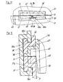
- a receptacle 71 adapted to the cross-sectional shape of the actuating button 23 is formed in the form of a depression.
- a labyrinth bush 72 protruding into the receptacle 71 is integrally formed in the central bottom region of this receptacle 71.
- the pin-shaped actuating part 73 of the on / off switch 62 extends into this labyrinth socket 72.
- the actuating button 23 is formed with an end wall 74, a peripheral wall 75 and a central, rear connecting shaft 76 which is to be plugged onto the actuating part 73 of the switch 62. Between the connecting shaft 76 and the peripheral wall 75, an annular cavity is formed on the rear side of the operating button 23, into which the labyrinth bush 72 projects to form a labyrinth seal in overlap with the connecting shaft 76 and the peripheral wall 75.
- the peripheral wall 75 forms a narrow slot 77 with the peripheral surface of the receptacle 71, which is sufficient for the safe, movable guidance of the actuating button 23, but also allows hardly any significant amounts of water to pass through even when heavily sprayed with water, for example in rain and storm.
- a channel-shaped water drain 78 is formed in the wall of the housing upper part 22 for emptying the receptacle 71, which leads from the bottom of the receptacle 71 to the outer surface of the housing upper part 22.
- the same design of receptacle and actuation button and labyrinth seal is also provided for the battery test switch 63 shown in FIG. 16.
- the on / off switch 62 and the battery test switch 63 or their actuating buttons 23 are arranged on the upper, outer corner regions of one end face of the upper housing part 22.
- troughs 79 are likewise formed in the upper, outer corner regions on the end face of the upper housing part opposite the receptacles 71 for the actuating buttons 23. These troughs are open towards the top and towards the respective side surface of the upper housing part 22. The depth of these troughs 79 corresponds essentially to the height of the screwed-on connecting terminals 25.
- the holder and buffer elements formed on the top of the intermediate floor 29 and on the inner surface of the ceiling wall 60 can of course be adapted to the respective requirements for holding together the pluggable circuit modules used and to be retained in the corresponding module receptacles.
- the device housing 20 offers particularly favorable options for the construction of the electrical circuit arrangement from circuit modules which are merely to be inserted into the module receptacles provided in each case and are to be electrically connected to one another by means of connecting lines to be plugged in. Apart from the holder and buffer elements, no other fastening devices are required for these circuit modules.
- the lower housing part 21 is matched to the power source to be accommodated, preferably a dry battery, in such a way that the power source or dry battery extends close to the opening edge of the lower housing part 21, to be precise within the opening of the housing Lower housing part 21 protruding circumferential wall part 30. This creates a secure cover for the upper edge of the current source 70 in the manner of a labyrinth seal.
- corresponding insert parts 80 - as indicated in FIG. 3 - are to be used.
Landscapes
- Life Sciences & Earth Sciences (AREA)
- Insects & Arthropods (AREA)
- Engineering & Computer Science (AREA)
- Microelectronics & Electronic Packaging (AREA)
- Casings For Electric Apparatus (AREA)
- Road Signs Or Road Markings (AREA)
Claims (21)
Priority Applications (1)
| Application Number | Priority Date | Filing Date | Title |
|---|---|---|---|
| AT82105803T ATE30827T1 (de) | 1981-08-18 | 1982-06-30 | Spritzwassergeschuetztes elektrisches geraet, vorzugsweise elektrozaungeraet. |
Applications Claiming Priority (2)
| Application Number | Priority Date | Filing Date | Title |
|---|---|---|---|
| DE3132524A DE3132524C2 (de) | 1981-08-18 | 1981-08-18 | Gerätegehäuse, insbesondere für Elektrozaungeräte |
| DE3132524 | 1981-08-18 |
Publications (3)
| Publication Number | Publication Date |
|---|---|
| EP0072417A2 EP0072417A2 (fr) | 1983-02-23 |
| EP0072417A3 EP0072417A3 (en) | 1984-11-07 |
| EP0072417B1 true EP0072417B1 (fr) | 1987-11-11 |
Family
ID=6139515
Family Applications (1)
| Application Number | Title | Priority Date | Filing Date |
|---|---|---|---|
| EP82105803A Expired EP0072417B1 (fr) | 1981-08-18 | 1982-06-30 | Dispositif électrique, en particulier dispositif de clôture électrique ayant une enveloppe étanche au jet d'eau |
Country Status (3)
| Country | Link |
|---|---|
| EP (1) | EP0072417B1 (fr) |
| AT (1) | ATE30827T1 (fr) |
| DE (1) | DE3132524C2 (fr) |
Families Citing this family (5)
| Publication number | Priority date | Publication date | Assignee | Title |
|---|---|---|---|---|
| ES266612Y (es) * | 1982-07-26 | 1983-09-01 | "aparato perfeccionado para cercas electricas". | |
| US4560827A (en) * | 1984-01-23 | 1985-12-24 | Howard Langlie | Electric fencer utilizing a sealed plastic housing |
| FR2586512B1 (fr) * | 1985-08-21 | 1988-06-03 | Phoenix Blocs Jonction Sarl | Coffret pour blocs de raccordement electrique |
| AT390542B (de) * | 1987-03-12 | 1990-05-25 | Siemens Ag Oesterreich | Sicherung gegen das oeffnen eines spannhebels mit blossen haenden |
| FR2924892B1 (fr) * | 2007-12-07 | 2009-12-18 | Lacme Holding | Boitier pour electrificateur |
Family Cites Families (8)
| Publication number | Priority date | Publication date | Assignee | Title |
|---|---|---|---|---|
| US2602844A (en) * | 1945-11-26 | 1952-07-08 | Babson Bros Co | Electric fence energizer |
| FR1215051A (fr) * | 1958-11-04 | 1960-04-13 | Pratica Soc | Perfectionnements aux boîtiers contenant les électrificateurs de clôture électrique |
| FR1301982A (fr) * | 1961-07-13 | 1962-08-24 | Coffret pour générateur d'impulsions et appareils similaires | |
| DE1838298U (de) * | 1961-07-24 | 1961-09-28 | Horizont Geraetewerk | Elektrisches weidezaungeraet. |
| DE1845058U (de) * | 1961-10-02 | 1962-01-18 | Heinz Dr Mueller | Weidezaungeraet. |
| FR1504634A (fr) * | 1966-10-10 | 1967-12-08 | Perfectionnements aux appareils électrificateurs de clôtures | |
| GB1201282A (en) * | 1968-03-28 | 1970-08-05 | A E C Electric Fencing | Improvements in electric fencing |
| US4227037A (en) * | 1979-05-29 | 1980-10-07 | Gulf & Western Manufacturing Company | Shielded non-metallic container |
-
1981
- 1981-08-18 DE DE3132524A patent/DE3132524C2/de not_active Expired
-
1982
- 1982-06-30 EP EP82105803A patent/EP0072417B1/fr not_active Expired
- 1982-06-30 AT AT82105803T patent/ATE30827T1/de not_active IP Right Cessation
Also Published As
| Publication number | Publication date |
|---|---|
| EP0072417A3 (en) | 1984-11-07 |
| DE3132524A1 (de) | 1983-03-10 |
| EP0072417A2 (fr) | 1983-02-23 |
| ATE30827T1 (de) | 1987-11-15 |
| DE3132524C2 (de) | 1985-02-28 |
Similar Documents
| Publication | Publication Date | Title |
|---|---|---|
| EP0678932B1 (fr) | Borne de raccordement et de connexion électrique | |
| DE19738772B4 (de) | Steckvorrichtung | |
| DE3807645C2 (de) | Steckverbindungssystem für elektrische Leiter | |
| DE69923051T2 (de) | Verriegelbarer elektrischer Steckverbinder | |
| DE102007025372B4 (de) | Gehäuse für einen Schutzschalter mit einer monolithischen bzw. einstückigen Tür | |
| DE10013111A1 (de) | Adapterplatte und System zur Anbringung eines Bauelementes auf eine Montageunterlage | |
| DE69509861T2 (de) | Modulare elektrische Vorrichtung | |
| DE4128928C2 (de) | Elektrische Verbindungseinheit für eine Hochdruck-Entladungslampe | |
| EP0702441B1 (fr) | Appareillage d'installation électrique, notamment pour canalisations de câbles | |
| EP1602158B1 (fr) | Ensemble de pieces pour une combinaison de dispositifs enfichables | |
| DE3942519A1 (de) | Elektrische anschlussklemme | |
| EP0072417B1 (fr) | Dispositif électrique, en particulier dispositif de clôture électrique ayant une enveloppe étanche au jet d'eau | |
| DE2917956A1 (de) | Wandanschlussdose | |
| DE69603884T2 (de) | Einrichtung zum Montieren einer Lampe | |
| DE4433617A1 (de) | Elektrisches Steckverbindungsteil | |
| DE69707217T2 (de) | Elektronische Verbindungsleiste zum Befestigung an einem Träger, insbesondere für autonome Notbeleuchtungsanlage | |
| EP0833547B1 (fr) | Dispositif de signalisation lumineux | |
| DE69607136T2 (de) | Schalttafel und Anschlusseinrichtung für elektrische Installationen mit modularen Einrichtungen | |
| DE2446912C3 (de) | Elektrische Baueinheit zum Montieren in einer elektrischen Anlage | |
| DE3230408A1 (de) | Offene rahmenklemme fuer elektrische schaltgeraete | |
| DE2517467C2 (de) | Abzweigkasten oder Abzweigdose für die Elektroinstallation | |
| DE3326906C2 (de) | Weidezaungerät | |
| AT395223B (de) | Zweipolige schutzkontaktsteckdose zum potentialfreien schliessen und oeffnen der steckverbindung | |
| EP0865110A2 (fr) | Dispositif de raccordement | |
| DE20204382U1 (de) | Gehäuse mit einem Trägerelement für ein Anschlußelement |
Legal Events
| Date | Code | Title | Description |
|---|---|---|---|
| PUAI | Public reference made under article 153(3) epc to a published international application that has entered the european phase |
Free format text: ORIGINAL CODE: 0009012 |
|
| AK | Designated contracting states |
Designated state(s): AT BE CH DE FR GB IT LI NL SE |
|
| PUAL | Search report despatched |
Free format text: ORIGINAL CODE: 0009013 |
|
| AK | Designated contracting states |
Designated state(s): AT BE CH DE FR GB IT LI NL SE |
|
| 17P | Request for examination filed |
Effective date: 19850205 |
|
| RBV | Designated contracting states (corrected) |
Designated state(s): AT BE CH FR GB IT LI NL SE |
|
| 17Q | First examination report despatched |
Effective date: 19860819 |
|
| GRAA | (expected) grant |
Free format text: ORIGINAL CODE: 0009210 |
|
| AK | Designated contracting states |
Kind code of ref document: B1 Designated state(s): AT BE CH FR GB IT LI NL SE |
|
| PG25 | Lapsed in a contracting state [announced via postgrant information from national office to epo] |
Ref country code: IT Free format text: LAPSE BECAUSE OF FAILURE TO SUBMIT A TRANSLATION OF THE DESCRIPTION OR TO PAY THE FEE WITHIN THE PRESCRIBED TIME-LIMIT;WARNING: LAPSES OF ITALIAN PATENTS WITH EFFECTIVE DATE BEFORE 2007 MAY HAVE OCCURRED AT ANY TIME BEFORE 2007. THE CORRECT EFFECTIVE DATE MAY BE DIFFERENT FROM THE ONE RECORDED. Effective date: 19871111 Ref country code: BE Effective date: 19871111 |
|
| REF | Corresponds to: |
Ref document number: 30827 Country of ref document: AT Date of ref document: 19871115 Kind code of ref document: T |
|
| PG25 | Lapsed in a contracting state [announced via postgrant information from national office to epo] |
Ref country code: SE Effective date: 19871130 |
|
| ET | Fr: translation filed | ||
| GBV | Gb: ep patent (uk) treated as always having been void in accordance with gb section 77(7)/1977 [no translation filed] | ||
| PLBE | No opposition filed within time limit |
Free format text: ORIGINAL CODE: 0009261 |
|
| STAA | Information on the status of an ep patent application or granted ep patent |
Free format text: STATUS: NO OPPOSITION FILED WITHIN TIME LIMIT |
|
| 26N | No opposition filed | ||
| PG25 | Lapsed in a contracting state [announced via postgrant information from national office to epo] |
Ref country code: GB Free format text: LAPSE BECAUSE OF NON-PAYMENT OF DUE FEES Effective date: 19881121 |
|
| PG25 | Lapsed in a contracting state [announced via postgrant information from national office to epo] |
Ref country code: LI Effective date: 19890630 Ref country code: CH Effective date: 19890630 Ref country code: AT Effective date: 19890630 |
|
| PG25 | Lapsed in a contracting state [announced via postgrant information from national office to epo] |
Ref country code: NL Effective date: 19900101 |
|
| NLV4 | Nl: lapsed or anulled due to non-payment of the annual fee | ||
| REG | Reference to a national code |
Ref country code: CH Ref legal event code: PL |
|
| PGFP | Annual fee paid to national office [announced via postgrant information from national office to epo] |
Ref country code: FR Payment date: 20000517 Year of fee payment: 19 |
|
| PG25 | Lapsed in a contracting state [announced via postgrant information from national office to epo] |
Ref country code: FR Free format text: LAPSE BECAUSE OF NON-PAYMENT OF DUE FEES Effective date: 20020228 |