EP0072639A2 - Getreidetrockner - Google Patents
Getreidetrockner Download PDFInfo
- Publication number
- EP0072639A2 EP0072639A2 EP82304037A EP82304037A EP0072639A2 EP 0072639 A2 EP0072639 A2 EP 0072639A2 EP 82304037 A EP82304037 A EP 82304037A EP 82304037 A EP82304037 A EP 82304037A EP 0072639 A2 EP0072639 A2 EP 0072639A2
- Authority
- EP
- European Patent Office
- Prior art keywords
- duct
- grain
- ducts
- grain dryer
- column
- Prior art date
- Legal status (The legal status is an assumption and is not a legal conclusion. Google has not performed a legal analysis and makes no representation as to the accuracy of the status listed.)
- Ceased
Links
Images

Classifications
-
- F—MECHANICAL ENGINEERING; LIGHTING; HEATING; WEAPONS; BLASTING
- F26—DRYING
- F26B—DRYING SOLID MATERIALS OR OBJECTS BY REMOVING LIQUID THEREFROM
- F26B17/00—Machines or apparatus for drying materials in loose, plastic, or fluidised form, e.g. granules, staple fibres, with progressive movement
- F26B17/12—Machines or apparatus for drying materials in loose, plastic, or fluidised form, e.g. granules, staple fibres, with progressive movement with movement performed solely by gravity, i.e. the material moving through a substantially vertical drying enclosure, e.g. shaft
- F26B17/14—Machines or apparatus for drying materials in loose, plastic, or fluidised form, e.g. granules, staple fibres, with progressive movement with movement performed solely by gravity, i.e. the material moving through a substantially vertical drying enclosure, e.g. shaft the materials moving through a counter-current of gas
- F26B17/1408—Machines or apparatus for drying materials in loose, plastic, or fluidised form, e.g. granules, staple fibres, with progressive movement with movement performed solely by gravity, i.e. the material moving through a substantially vertical drying enclosure, e.g. shaft the materials moving through a counter-current of gas the gas being supplied and optionally extracted through ducts extending into the moving stack of material
- F26B17/1416—Machines or apparatus for drying materials in loose, plastic, or fluidised form, e.g. granules, staple fibres, with progressive movement with movement performed solely by gravity, i.e. the material moving through a substantially vertical drying enclosure, e.g. shaft the materials moving through a counter-current of gas the gas being supplied and optionally extracted through ducts extending into the moving stack of material the ducts being half open or perforated and arranged horizontally
Definitions
- the present invention relates to grain dryers.
- a dryer according to the present invention which comprises a column through which drying air and grain may be passed, drying air ducts extending substantially horizontally across the column, the ducts each having a closed top and sides extending downwards from the top, the boundary of the effective lower edge of each side exposable to grain in the colunn being substantially longer than the horizontal length of the duct exposable to grain in the column.
- each side is formed with a deeply indented edge.
- a castellated edge has been successfully tried.
- each side may be formed with closed slots the lower edge of which is then bent back across the slots so that the slots are open at the lowest portion of the edge.
- a comb is thus formed with the tips or comb teeth strengthened by the bent back portion.
- the free edge (as compared with the effective edge which is formed at the line where the lower edge is bent) may then be bent down inwardly of the effective edge.
- the substantial lengthening of the boundary of the effective lower edge has the effect of lengthening the edge of the duct in contact with the grain which results in a substantial reduction of air flow speed at the lower edge. This reduces or eliminates the tendency of the drying air to pick up grain and draw this into each duct.
- each duct are preferably formed with a triangular apex, the apex angle being for example, 60°. This has been found to provide an advantage in assisting grain flow around the top of the duct.
- Fig. 1 three ducts 2, 2' and 2" are shown mounted horizontally across a grain dryer column 3. In practice there will usually be more than three ducts and often more than one tier of ducts.
- Drying air shown by firm arrows 4 is passed down through the column in which a descending bed of grain, shown by broken arrow 5, also flows. Drying air when it reaches the ducts 2 - 2" may flow through and beneath the straight duct sides 7 into the inside 8 of each duct one of which is shown in more detail in Fig. 2. The grain continues downwards below the ducts forming open surfaces 10 under each duct, whilst the drying air exits from an end of the duct.
- each duct The sides 7 of each duct are substantially vertical and parallel to each other and towards the bottom have a plate 14 welded, rivetted or bolted to them extending the sides downwards and providing a comb.
- the comb has teeth 16 and gaps 18 between the teeth open at the effective lower edge 19, so that the effective lower edge boundary formed by the sides and bottom edge 15 of the teeth 16 and root 17 of the gaps 18 is very substantially longer than the horizontal length 20 of the duct.
- the plate 14 is bent slightly outwards (say 9°) about a line 21, and abruptly inwards (say 99°) about a line 22'to form the effective edge 19, the lines 21 and 22 being parallel with the elongate axis 24 of the duct.
- the plate 14 is slotted with closed slots which at the bend line form the comb gaps 18 above for ease of manufacture and for strength.
- the plate 14 is further bent downwards (say 90°) about a line 23 parallel with axis 24 to form a stiffening edge portion 25,the free edge of which is positioned inwardly of the effective edge 19.
- the grain speed increases as does also the air speed.
- the comb like lower edge of the duct slows the air to prevent the air drawing grains up into the duct and also the volume of air reaching the lower edge is reduced by the seepage of air through the slots as it travels down around the duct sides.
- the apex 12 of the top of the duct is angled at 60° which smoothes the grain flow around the duct top and which helps to prevent dead areas of slow moving or immobile grain above the ducts.
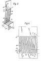
- Fig. 3 is another view of the comb plate of Fig. 2 and Fig. 4 shows the comb plate of Fig. 3 prior to bending.
- the slot widths may each be 1.2-1.4 mm with a tooth width of the slots 3.6-3.8 mm the gap length is 65 mm from edge 19 to root 17. It will thus be appreciated that the boundary length of the bottom effective edge of the duct is very substantially longer than the length of the duct.
- the comb can be replaced by a castellated configuration but this is more difficult to construct and strengthen.
- Other configurations may be provided for instance the plate portion between bends 22 and 23 may be sloped downwards to assist in cleaning the duct and comb, or else this portion can be bent upwards but the comb configuration provides a very large lower edge boundary increase which effectively slows the air flow at the point where the drying air enters the duct. Seepage of air moving downwards with the grain is allowed before the bottom edge of the comb thus any air reaching this level will be relatively small in volume and at a low velocity.
- Air seepage into the duct could be achieved via any suitable perforations with perforations smaller than the grain but this could easily become blocked if the comb arrangement of the invention were not followed.
- the comb arrangement enables the gaps between the comb teeth to be kept clear due to the effective open bottom end of the gaps.
Landscapes
- Engineering & Computer Science (AREA)
- Mechanical Engineering (AREA)
- General Engineering & Computer Science (AREA)
- Drying Of Solid Materials (AREA)
Applications Claiming Priority (2)
| Application Number | Priority Date | Filing Date | Title |
|---|---|---|---|
| GB8125170 | 1981-08-18 | ||
| GB8125170 | 1981-08-18 |
Publications (2)
| Publication Number | Publication Date |
|---|---|
| EP0072639A2 true EP0072639A2 (de) | 1983-02-23 |
| EP0072639A3 EP0072639A3 (de) | 1984-10-17 |
Family
ID=10524012
Family Applications (1)
| Application Number | Title | Priority Date | Filing Date |
|---|---|---|---|
| EP82304037A Ceased EP0072639A3 (de) | 1981-08-18 | 1982-07-30 | Getreidetrockner |
Country Status (4)
| Country | Link |
|---|---|
| EP (1) | EP0072639A3 (de) |
| DK (1) | DK368282A (de) |
| GB (1) | GB2106229B (de) |
| GR (1) | GR76253B (de) |
Cited By (1)
| Publication number | Priority date | Publication date | Assignee | Title |
|---|---|---|---|---|
| US20230098343A1 (en) * | 2021-09-30 | 2023-03-30 | The Gsi Group, Llc | Grain dryer with bypass air control |
Family Cites Families (6)
| Publication number | Priority date | Publication date | Assignee | Title |
|---|---|---|---|---|
| DE142446C (de) * | 1900-12-25 | 1903-07-10 | ||
| DE1012261B (de) * | 1950-07-25 | 1957-07-11 | John Brockbank Carr | Aus etagenweise uebereinanderliegenden Zellen bestehender Rieselschachttrockner |
| FR1160101A (fr) * | 1956-10-25 | 1958-07-08 | Linde Kvarnmaskiner Ab | Séchoir notamment pour céréales |
| US3302297A (en) * | 1964-09-09 | 1967-02-07 | Douglas L Graham | Drying apparatus and method |
| GB1547986A (en) * | 1976-06-16 | 1979-07-04 | Bentall & Co Ltd E H | Floor mounted air ducts in grain drying systems |
| DE2906358B2 (de) * | 1979-02-19 | 1981-04-02 | Goldsaat Fritz Döring GmbH & Co KG, 5630 Remscheid | Vorrichtung zum kontinuierlichen Trocknen von Korngut, insbe. Mais |
-
1982
- 1982-07-30 GB GB08222014A patent/GB2106229B/en not_active Expired
- 1982-07-30 EP EP82304037A patent/EP0072639A3/de not_active Ceased
- 1982-08-13 GR GR69037A patent/GR76253B/el unknown
- 1982-08-17 DK DK368282A patent/DK368282A/da unknown
Cited By (2)
| Publication number | Priority date | Publication date | Assignee | Title |
|---|---|---|---|---|
| US20230098343A1 (en) * | 2021-09-30 | 2023-03-30 | The Gsi Group, Llc | Grain dryer with bypass air control |
| US12535271B2 (en) * | 2021-09-30 | 2026-01-27 | The Gsi Group, Llc | Grain dryer with bypass air control |
Also Published As
| Publication number | Publication date |
|---|---|
| GB2106229A (en) | 1983-04-07 |
| DK368282A (da) | 1983-02-19 |
| GR76253B (de) | 1984-08-04 |
| EP0072639A3 (de) | 1984-10-17 |
| GB2106229B (en) | 1984-11-28 |
Similar Documents
| Publication | Publication Date | Title |
|---|---|---|
| US4876827A (en) | Gutter assembly | |
| US8720870B2 (en) | Contact tray for a mass transfer column | |
| DE60022847T2 (de) | Kombinierte endlose Rippe für Wärmetauscher | |
| US5542224A (en) | Louver | |
| SU1746877A3 (ru) | Бесконечна конвейерна лента | |
| US4169407A (en) | Side wall construction for a container for shipping goods | |
| US4247397A (en) | Eaves trough shield | |
| US4382401A (en) | Air distribution apparatus, especially for oversaturated air | |
| US5203894A (en) | Mist eliminator blade spacer | |
| DE69614412T2 (de) | Blaskasten zur anwendung in einer trockenanlage für materialbahnen | |
| US4286507A (en) | Shipping container construction | |
| US2882996A (en) | Cooling tower mist eliminator | |
| GB2106229A (en) | Grain dryers | |
| EP0501146B1 (de) | Tropfenabscheider mit Wabenstruktur | |
| EP0592707B1 (de) | Abscheider für eine Einrichtung zum Be- und Entlüften von Räumen | |
| DE478377C (de) | Plattenfoermige, in die Richtung des Gasstromes zu stellende Niederschlagselektrode fuer elektrische Gasreinigungsanlagen | |
| CA2428182A1 (en) | Baffle system for separating liquid from a gas stream | |
| DE2509652B2 (de) | Anlage zum Kühlen durch Verdunsten von Flüssigkeit | |
| JP7219976B2 (ja) | 雨樋構造および雨樋カバー | |
| EP0281981A2 (de) | Tropfenabscheider zum Einbau in einen im wesentlichen senkrecht angeordneten Strömungskanal | |
| SE452898B (sv) | Teckplat for bekledning av yttertak och ytterveggar pa byggnader | |
| KR960010382Y1 (ko) | 양계용 케이지의 저판구조 | |
| JP3332720B2 (ja) | ミストの除去方法及び装置 | |
| DE8133389U1 (de) | Transportbehaelter mit lueftungsoeffnungen im bereich der oberen und unteren traeger | |
| EP0194527A2 (de) | Vorrichtung zum Be- und/oder Entlüften von Räumen |
Legal Events
| Date | Code | Title | Description |
|---|---|---|---|
| PUAI | Public reference made under article 153(3) epc to a published international application that has entered the european phase |
Free format text: ORIGINAL CODE: 0009012 |
|
| AK | Designated contracting states |
Designated state(s): AT CH DE FR IT LI NL SE |
|
| PUAL | Search report despatched |
Free format text: ORIGINAL CODE: 0009013 |
|
| AK | Designated contracting states |
Designated state(s): AT CH DE FR IT LI NL SE |
|
| 17P | Request for examination filed |
Effective date: 19841022 |
|
| STAA | Information on the status of an ep patent application or granted ep patent |
Free format text: STATUS: THE APPLICATION HAS BEEN REFUSED |
|
| 18R | Application refused |
Effective date: 19860607 |
|
| RIN1 | Information on inventor provided before grant (corrected) |
Inventor name: LAYTON, TERENCE WILLIAM Inventor name: LEWIS, HAROLD GEORGE GOLDEN |