EP0072655A2 - Münzabweisungsvorrichtung - Google Patents
Münzabweisungsvorrichtung Download PDFInfo
- Publication number
- EP0072655A2 EP0072655A2 EP82304182A EP82304182A EP0072655A2 EP 0072655 A2 EP0072655 A2 EP 0072655A2 EP 82304182 A EP82304182 A EP 82304182A EP 82304182 A EP82304182 A EP 82304182A EP 0072655 A2 EP0072655 A2 EP 0072655A2
- Authority
- EP
- European Patent Office
- Prior art keywords
- coin
- impedance
- approach
- detector
- coils
- Prior art date
- Legal status (The legal status is an assumption and is not a legal conclusion. Google has not performed a legal analysis and makes no representation as to the accuracy of the status listed.)
- Granted
Links
Images
Classifications
-
- G—PHYSICS
- G07—CHECKING-DEVICES
- G07D—HANDLING OF COINS OR VALUABLE PAPERS, e.g. TESTING, SORTING BY DENOMINATIONS, COUNTING, DISPENSING, CHANGING OR DEPOSITING
- G07D5/00—Testing specially adapted to determine the identity or genuineness of coins, e.g. for segregating coins which are unacceptable or alien to a currency
- G07D5/08—Testing the magnetic or electric properties
Definitions
- the present invention relates to a coin rejector device of a type utilizing proximity switches.
- Such a coin rejector device utilizing proximity switches is disclosed in a Japanese Patent Application Pubiication No. 16,527/1971.
- the coin rejector device disclosed in the above Publication includes two proximity switches having detector coils in the form of generator or oscillator coils, respectively, each of which ceases its oscillation when the load impedance becomes lower than a predetermined value upon the approach of a coin to the detector coil and in which the oscillator of one of the proximity switches is preset to such an oscillation frequency that the load impedance upon the approach of the legal or acceptable coin to the detector coil becomes higher than any load impedance upon the approach of at least one of the illegal or unacceptable coins while the oscillator of the other proximity switch is preset to such an oscillation frequency that the load impedance upon the approach of the legal coin to the detector coil becomes lower than the load impedance upon the approach of the other illegal coins except the above at least one illegal coin.
- such a known coin rejector device has a disadvantage that it can not select the legal coin from an illegal coin modified by drilling a small hole or holes therethrough so as to provide the same load impedance as that by the legal coin. For example, if an illegal brass coin has a small hole drilled therethrough, it provides the same impedance as that of the legal one-hundred yen nickel coin when the illegal brass coin approaches to the detector coil so that it could not prevent unfair use of such modified illegal coins.
- the object of the invention is to provide a coin rejector device employing two or more proximity switches having detector coils in the form of generator or oscillator coils, respectively, each of which generates an output when the load impedance becomes lower than a threshold value upon the approach of a coin to the detector coil and in which the threshold value is preset to an impedance which is higher than that provided upon the approach of the legal coin to the detector coil for improving the coin selecting precision and preventing the unfair use of illegal coin having a hole.
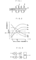
- Fig. 1 there is shown a coin detecting portion of the coin rejector device utilizing two proximity switches. It will be seen that detector coils 1 and 2 in the form of generator or oscillator coils, respectively, are fixedly arranged along a coin selecting passage 3 so that when a coin 4 inserted into the coin rejector device passes through the passage 3 in the direction as shown by an arrow, the impedance of each of the detector coils 1 and 2 is varied.
- Fig. 2 there are shown impedance performance curves by illegal coins having the same diameter and thickness as that of the legal nickel coin and made of stainless steel (Su), iron (Fe), nickel silver (Ns), lead (Pb), and brass (Bs), while the impedance (Z) on the approach of the legal nickel coin to the detector is 1.
- the oscillation frequency (f) of the detector coil without the approach of the coin is indicated on the abscissa axis and the impedance (Z) upon the approach of the coin to the detector preset at the oscillation frequency (f) is indicated on the ordinate axis.
- the proximity switch S l has an output which is transmitted to an AND circuit through a delay circuit D 1 .
- the legal nickel coin and the illegal coins made of brass, nickel silver and lead are detected.
- the proximity switch S 2 When the impedance by the approach of the coin to .the second detector coil 2 is lower than the threshold value Z 2 , the proximity switch S 2 has then an output which is also transmitted to the AND circuit through a delay circuit D 2 . At this time, the legal nickel coin and the illegal coins made of iron and stainless steel are detected. Accordingly, the AND circuit has an output only when the inserted coin is the legal nickel coin.
- the coin rejector device including two or more proximity switches each of which has an output when the impedance on the approach of the coin to the detector coil is lower than the threshold value and the threshold values being higher than the impedance on the approach of the legal coin to the detector coils so that it is possible to make a large difference between the impedance by the legal coin and the threshold value as shown in Fig. 2 and thus to prevent the coin selecting precision from affecting by any change of the impedance caused from the change of conditions on the approach of the coin to the detector coil and hence the position of the coin relative to the detector coil and further prevent the unfair use of illegal coin with a hole.
Landscapes
- Physics & Mathematics (AREA)
- General Physics & Mathematics (AREA)
- Testing Of Coins (AREA)
Applications Claiming Priority (2)
| Application Number | Priority Date | Filing Date | Title |
|---|---|---|---|
| JP11766781U JPS5824870U (ja) | 1981-08-10 | 1981-08-10 | 硬貨選別装置 |
| JP117667/81U | 1981-08-10 |
Publications (3)
| Publication Number | Publication Date |
|---|---|
| EP0072655A2 true EP0072655A2 (de) | 1983-02-23 |
| EP0072655A3 EP0072655A3 (en) | 1983-12-07 |
| EP0072655B1 EP0072655B1 (de) | 1986-06-04 |
Family
ID=14717297
Family Applications (1)
| Application Number | Title | Priority Date | Filing Date |
|---|---|---|---|
| EP19820304182 Expired EP0072655B1 (de) | 1981-08-10 | 1982-08-09 | Münzabweisungsvorrichtung |
Country Status (5)
| Country | Link |
|---|---|
| EP (1) | EP0072655B1 (de) |
| JP (1) | JPS5824870U (de) |
| AU (1) | AU536534B2 (de) |
| DE (1) | DE3271552D1 (de) |
| HK (1) | HK28787A (de) |
Cited By (1)
| Publication number | Priority date | Publication date | Assignee | Title |
|---|---|---|---|---|
| WO1993022747A1 (en) * | 1992-05-06 | 1993-11-11 | Mars Incorporated | Coin validator |
Families Citing this family (3)
| Publication number | Priority date | Publication date | Assignee | Title |
|---|---|---|---|---|
| JPH07120453B2 (ja) * | 1989-02-17 | 1995-12-20 | 富士電機株式会社 | 電子式硬貨選別装置の硬貨返却信号発生装置 |
| JP6175241B2 (ja) * | 2013-01-31 | 2017-08-02 | 日本電産サンキョー株式会社 | コイン状被検出体識別装置およびコイン状被検出体識別装置の制御方法 |
| CN104919497B (zh) * | 2013-01-31 | 2017-05-17 | 日本电产三协株式会社 | 硬币状被检测体识别装置以及硬币状被检测体识别装置的控制方法 |
Family Cites Families (8)
| Publication number | Priority date | Publication date | Assignee | Title |
|---|---|---|---|---|
| FR1283263A (fr) * | 1960-12-20 | 1962-02-02 | Signaux Entr Electriques | Sélecteur de jetons |
| US3373856A (en) * | 1966-01-18 | 1968-03-19 | Canadian Patents Dev | Method and apparatus for coin selection |
| JPS443281Y1 (de) * | 1966-07-19 | 1969-02-06 | ||
| US3870137A (en) * | 1972-02-23 | 1975-03-11 | Little Inc A | Method and apparatus for coin selection utilizing inductive sensors |
| JPS4927278U (de) * | 1972-06-07 | 1974-03-08 | ||
| DE2915719A1 (de) * | 1979-04-19 | 1980-11-13 | Pruemm Georg | Elektronischer muenzpruefer |
| GB2068621B (en) * | 1980-02-06 | 1983-12-14 | Mars Inc | Testing coins |
| GB9010526D0 (en) * | 1990-05-10 | 1990-07-04 | Unilever Plc | Cosmetic composition |
-
1981
- 1981-08-10 JP JP11766781U patent/JPS5824870U/ja active Pending
-
1982
- 1982-08-03 AU AU86708/82A patent/AU536534B2/en not_active Ceased
- 1982-08-09 DE DE8282304182T patent/DE3271552D1/de not_active Expired
- 1982-08-09 EP EP19820304182 patent/EP0072655B1/de not_active Expired
-
1987
- 1987-04-09 HK HK28787A patent/HK28787A/xx unknown
Cited By (2)
| Publication number | Priority date | Publication date | Assignee | Title |
|---|---|---|---|---|
| WO1993022747A1 (en) * | 1992-05-06 | 1993-11-11 | Mars Incorporated | Coin validator |
| US5609234A (en) * | 1992-05-06 | 1997-03-11 | Walker; Robert S. | Coin validator |
Also Published As
| Publication number | Publication date |
|---|---|
| JPS5824870U (ja) | 1983-02-17 |
| HK28787A (en) | 1987-04-16 |
| AU536534B2 (en) | 1984-05-10 |
| AU8670882A (en) | 1983-04-14 |
| EP0072655B1 (de) | 1986-06-04 |
| EP0072655A3 (en) | 1983-12-07 |
| DE3271552D1 (en) | 1986-07-10 |
Similar Documents
| Publication | Publication Date | Title |
|---|---|---|
| US3901368A (en) | Coin acceptor/rejector | |
| US4105105A (en) | Method for checking coins and coin checking apparatus for the performance of the aforesaid method | |
| ES8303756A1 (es) | Aparato para verificar la validez de monedas. | |
| US3918563A (en) | Coin arrival sensor | |
| US4587486A (en) | Switch for detecting a magnetic field | |
| EP0724237B1 (de) | Münzsortiervorrichtung | |
| US4471864A (en) | Slug rejector | |
| CA2302922A1 (en) | Dual coil coin identifier | |
| US3576244A (en) | Coin acceptor having resistivity and permeability detector | |
| DE69324371T2 (de) | Sicherheitshalteeinrichtung | |
| US4091908A (en) | Coin checking device for a vending machine | |
| EP0072655A2 (de) | Münzabweisungsvorrichtung | |
| US4398626A (en) | Low frequency phase shift coin examination method and apparatus | |
| EP0110510B1 (de) | Selbstabstimmende niederfrequente phasenverschiebende Münzprüfmethode und -vorrichtung | |
| EP0363902A2 (de) | Methode zur Ermittlung des Verschleisses von Schneidwerkzeugen | |
| AU700627B2 (en) | Coin detection device and associated method | |
| EP0316308A1 (de) | Detektorvorrichtung für münzen | |
| US4226323A (en) | Precision coin analyzer for numismatic application | |
| EP0051017B1 (de) | Münzannahme- oder -rückgabevorrichtung | |
| MY103978A (en) | Coin discriminator | |
| RU2213374C2 (ru) | Дискриминатор для биметаллических монет | |
| DE68905462T2 (de) | Beruehrungswarnehmungsvorrichtung eines maschinenwerkzeuges. | |
| AU7785591A (en) | Method and apparatus for testing coins | |
| JPS586985B2 (ja) | 硬貨選別装置 | |
| ZA818443B (en) | Switching arrangements in coin testers |
Legal Events
| Date | Code | Title | Description |
|---|---|---|---|
| PUAI | Public reference made under article 153(3) epc to a published international application that has entered the european phase |
Free format text: ORIGINAL CODE: 0009012 |
|
| AK | Designated contracting states |
Designated state(s): DE FR GB IT NL SE |
|
| PUAL | Search report despatched |
Free format text: ORIGINAL CODE: 0009013 |
|
| 17P | Request for examination filed |
Effective date: 19830819 |
|
| AK | Designated contracting states |
Designated state(s): DE FR GB IT NL SE |
|
| RAP1 | Party data changed (applicant data changed or rights of an application transferred) |
Owner name: ASAHI SEIKO KABUSHIKI KAISHA |
|
| GRAA | (expected) grant |
Free format text: ORIGINAL CODE: 0009210 |
|
| AK | Designated contracting states |
Kind code of ref document: B1 Designated state(s): DE FR GB IT NL SE |
|
| ITF | It: translation for a ep patent filed | ||
| REF | Corresponds to: |
Ref document number: 3271552 Country of ref document: DE Date of ref document: 19860710 |
|
| ET | Fr: translation filed | ||
| PLBE | No opposition filed within time limit |
Free format text: ORIGINAL CODE: 0009261 |
|
| STAA | Information on the status of an ep patent application or granted ep patent |
Free format text: STATUS: NO OPPOSITION FILED WITHIN TIME LIMIT |
|
| 26N | No opposition filed | ||
| PGFP | Annual fee paid to national office [announced via postgrant information from national office to epo] |
Ref country code: NL Payment date: 19870831 Year of fee payment: 6 |
|
| PG25 | Lapsed in a contracting state [announced via postgrant information from national office to epo] |
Ref country code: GB Effective date: 19890809 |
|
| PG25 | Lapsed in a contracting state [announced via postgrant information from national office to epo] |
Ref country code: SE Effective date: 19890810 |
|
| PG25 | Lapsed in a contracting state [announced via postgrant information from national office to epo] |
Ref country code: NL Effective date: 19900301 |
|
| GBPC | Gb: european patent ceased through non-payment of renewal fee | ||
| NLV4 | Nl: lapsed or anulled due to non-payment of the annual fee | ||
| PG25 | Lapsed in a contracting state [announced via postgrant information from national office to epo] |
Ref country code: FR Effective date: 19900427 |
|
| PG25 | Lapsed in a contracting state [announced via postgrant information from national office to epo] |
Ref country code: DE Effective date: 19900501 |
|
| REG | Reference to a national code |
Ref country code: FR Ref legal event code: ST |
|
| EUG | Se: european patent has lapsed |
Ref document number: 82304182.7 Effective date: 19900418 |