EP0072665A2 - Pneumatisches Steuerungssystem für Maschinen - Google Patents
Pneumatisches Steuerungssystem für Maschinen Download PDFInfo
- Publication number
- EP0072665A2 EP0072665A2 EP82304244A EP82304244A EP0072665A2 EP 0072665 A2 EP0072665 A2 EP 0072665A2 EP 82304244 A EP82304244 A EP 82304244A EP 82304244 A EP82304244 A EP 82304244A EP 0072665 A2 EP0072665 A2 EP 0072665A2
- Authority
- EP
- European Patent Office
- Prior art keywords
- pressure
- pulses
- air
- reservoir
- actuator
- Prior art date
- Legal status (The legal status is an assumption and is not a legal conclusion. Google has not performed a legal analysis and makes no representation as to the accuracy of the status listed.)
- Withdrawn
Links
Images


Classifications
-
- G—PHYSICS
- G05—CONTROLLING; REGULATING
- G05B—CONTROL OR REGULATING SYSTEMS IN GENERAL; FUNCTIONAL ELEMENTS OF SUCH SYSTEMS; MONITORING OR TESTING ARRANGEMENTS FOR SUCH SYSTEMS OR ELEMENTS
- G05B19/00—Program-control systems
- G05B19/43—Program-control systems fluidic
- G05B19/44—Program-control systems fluidic pneumatic
-
- G—PHYSICS
- G05—CONTROLLING; REGULATING
- G05B—CONTROL OR REGULATING SYSTEMS IN GENERAL; FUNCTIONAL ELEMENTS OF SUCH SYSTEMS; MONITORING OR TESTING ARRANGEMENTS FOR SUCH SYSTEMS OR ELEMENTS
- G05B2219/00—Program-control systems
- G05B2219/30—Nc systems
- G05B2219/41—Servomotor, servo controller till figures
- G05B2219/41156—Injection of vibration anti-stick, against static friction, dither, stiction
-
- G—PHYSICS
- G05—CONTROLLING; REGULATING
- G05B—CONTROL OR REGULATING SYSTEMS IN GENERAL; FUNCTIONAL ELEMENTS OF SUCH SYSTEMS; MONITORING OR TESTING ARRANGEMENTS FOR SUCH SYSTEMS OR ELEMENTS
- G05B2219/00—Program-control systems
- G05B2219/30—Nc systems
- G05B2219/41—Servomotor, servo controller till figures
- G05B2219/41309—Hydraulic or pneumatic drive
-
- G—PHYSICS
- G05—CONTROLLING; REGULATING
- G05B—CONTROL OR REGULATING SYSTEMS IN GENERAL; FUNCTIONAL ELEMENTS OF SUCH SYSTEMS; MONITORING OR TESTING ARRANGEMENTS FOR SUCH SYSTEMS OR ELEMENTS
- G05B2219/00—Program-control systems
- G05B2219/30—Nc systems
- G05B2219/42—Servomotor, servo controller kind till VSS
- G05B2219/42237—Pwm pulse width modulation, pulse to position modulation ppm
-
- G—PHYSICS
- G05—CONTROLLING; REGULATING
- G05B—CONTROL OR REGULATING SYSTEMS IN GENERAL; FUNCTIONAL ELEMENTS OF SUCH SYSTEMS; MONITORING OR TESTING ARRANGEMENTS FOR SUCH SYSTEMS OR ELEMENTS
- G05B2219/00—Program-control systems
- G05B2219/30—Nc systems
- G05B2219/45—Nc applications
- G05B2219/45083—Manipulators, robot
Definitions
- Control systems for precise operation of mechanisms such as machine tools, industrial robots and the like are usually electrical or hydraulic. Both types are expensive and use bulky and heavy motors and actuators and much wiring or tubing capable of carrying considerable power or hydraulic pressure. In large machine tools the weight is not critical, but on any moving apparatus where the power drive or structure becomes part of the load, such as a jointed arm robot, any excess weight on the moving components adds to the load that must be moved and this increases the power requirements, and thus the cost.
- Pneumatic power systems are much lighter and simpler and considerably lower in cost than equivalent hydraulic or electic systems, but are usually not considered suitable for precise servoed machine control due to the compressibility and cushioning effect of air as a driving medium.
- a pneumatic power system would make it possible to greatly reduce the weight, complexity and cost of industrial robots in particular and power actuated machinery in general.
- the pneumatic control system illustrated herein is capable of operating a variety of machines, industrial robots and the like, with great precision and with a minimum of associated power and control apparatus.
- a pneumatic control system for machines which system is responsive to a source of compressed air, comprising: a pressure storage reservoir having an outlet; a pressure control valve means coupled between the source of air and the reservoir for controlling air flow to said reservoir; a pneumatic actuator; and valve means coupled between said outlet and said actuator and having timing means for applying short pulses of compressed air to said actuator.
- One feature that makes the preferred system practical is the technique of controlling the air flow through valves that are actuated by digital pulse signals in a particular manner.
- a supply of compressed air is maintained in a reservoir at a precise predetermined minimum pressure necessary for a particular operation, resulting in minimum wastage of air and considerable savings in the energy needed to compress the air.
- Air flow to a particular actuator is controlled by a directional control valve and a speed control.valve, which are digitally pulsed to provide the required motion.
- each pulse signal provides a sharp pulse of air pressure that instantly overcomes the static friction of the associated mechanism and produces a precise increment of movement that is under a feedback control.
- the signal is continuous and the power application is additional.
- the digital dithering technique uses individual pulses, each of which breaks the static friction and moves the mechanism. Thus a single pulse provides just as positive and precise a motion as continuous pulses.
- a pulse generator controlled by a computer produces the digital pulses, the pulse rate and pulse width being under variable control to provide the required increments speed and acceleration of movement.
- Differential dithering by which more power is applied in one direction of movement than the other, can be used to support or overcome an offset load, and also to provide more precise positioning of the load or working unit.
- a feature of the preferred pneumatic control system is that air flow is controlled by digitally pulsed valves, with each pulse breaking the static friction of the mechanism and providing a precise increment of movement.
- the primary object of this invention is to provide a new and improved pneumatic control system for machines.
- Another object of this invention is to provide a new and improved pneumatic control system that is adaptable to a variety of machines, industrial robots and the like.
- a further object of this invention is to provide a new and improved pneumatic control system that is simpler and lighter but capable of more precise operation than a comparable hydraulic or electrical system.
- a further object of this invention is to provide a new and improved pneumatic control system that is particularly useful in robots and that provides optomized and efficient use of pressurized air.
- a further object of this invention is to provide a new and improved pneumatic control system that is particularly adapted for computer control.
- compressed air is obtained from a suitable source 10 through a pressure regulator 12, which may be a standard shop air supply or compressor installation. Usually this type of air supply is at a much higher pressure than needed for the present system and is not at a particularly constant pressure. Accurate air pressure is necessary for proper calibration and efficiency of the system, so the air is fed through a solenoid, pulse operated pressure control valve 14 to a reservoir 16. Valve 14 is actuated by digital pulse signals from a pulse generator 18, the action of which will be described later, with the air thus entering the reservoir 16 in pulses. The pulsing of air provides a precisely controlled air pressure in pressure reservoir 16, which air pressure is controlled using closed loop pressure feedback under computer control.
- the air supplied through the pulses can be changed quickly enough to be able to maintain a relatively precise, given air pressure in reservoir 16, regardless of the air draw through line 22 and while using a relatively small accummulator 16.
- the reservoir is internally damped in any suitable manner, such as by an insert of resilient material, baffles, or the like, the arrangement being well known.
- a very precise constant pressure can be maintained in'the reservoir and a suitable pressure guage 20 is provided at the outlet 22 for visual checking.
- Outlet 22 is coupled to the inlet 24 of a solenoid operated, two way directional control valve 26. which has a pair of control outlets 28 and 30 and a pair of vent outlets 32.
- the control outlets 28 and 30 are coupled to opposite sides of a reversible air motor 34, such as a positive displacement type or a conventional vane motor.
- Valve 26 is also actuated by digital pulse signals from the pulse generator 18 for rapid directional control of motor 34.
- Vent outlets 32 are both coupled to a solenoid operated speed control, air valve 36, that is also actuated by pulse generator 18 to vent pulses of air to the atmosphere.
- the speed control valve 36 as_ controlled by the pulse generator 18, vents air pulses of controlled width and controlled timing and thus controls the speed of motor 34, while valve 26 controls the direction, and can control the speed, of rotation.
- air valves 14, 26 and 36 function to provide controlled air pressure and volume to obtain controlled movement, speed and economy.
- Pulse generator 18 provides controlled variable pulse rate and pulse width signals to solenoic control valves 14, 26 and 36.
- the circuitry for providing this is well known and suitable pulse generators are currently available.
- Operation of the system is controlled by a computer 38, which can be an available general purpose type in which digital type programs can be stored for a variety of operations.
- a pressure feedback 45 from reservoir 16 is supplied to computer 38 for reference, so that the required pressure in the reservoir can be maintained by, for example, increasing or decreasing the number of control pulses from pulse generator 18 to solenoid valve 14.
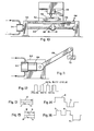
- FIG. 2 illustrates the system with the valve functions indicated and motor 34 is shown connected to a rotary jack screw 44 on which is a traveller 46, as an example.
- a single operating channel is shown for purposes of description, but it will be obvious that any reasonable number of cnannels, each with its own speed and directional control valves and if desired its own separately controlled air supply, may be used.
- the system is thus adaptable to a variety of multiple axis control machines.
- Figure 10 shows a milling machine 48 in basic form.
- Motor 34 is mounted on the base frame 50 and drives the longitudinal jack screw 44.
- Traveller 46 is attached to a carriage 52 which rides on longitudinal ways 54 and carries a part 56 under the tool head 58.
- a roller type indicator 60 is mounted on carriage 52 and rides on ways 54 to measure the motion of the carriage and provide the position feedback through 61 and 42 to the computer 38.
- Any suitable position indicator or transducer can be used, preferably of a micrometer type capable of providing very precise readings in order to be compatible with the accuracy of the system, and that provides electrical signal information reflecting the precise readings to the computer 38.
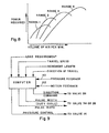
- air pressure is usually applied to an actuator or motor through a valve, which may be a simple on and off or a variable flow rate type valve. All mechanisms actuated by fluid pressure are usually close fitting in order to contain the pressure and thus have a certain amount of friction. To start an actuator moving, this starting or static friction must first be overcome by sufficient pressure, then the actuator will move until the pressure drops below that necessary to sustain motion.
- the initial pressure builds up gradually until at point A the static friction is overcome and drops off rapidly as the control function is completed B. Once the static friction is broken, the pressure necessary to sustain motion may actually be less, depending on the mechanism being driven. As illustrated the static friction breaking pressure is about 100 units on an arbitrary scale. which could be p.s.i., Pascals, or any other suitable measure.
- the air pressure is applied in very sharp pulses through valves which are capable of fast poppet or snap action between fully closed and fully open, so that full working pressure is applied almost instantly.
- the sudden pulse of pressure breaks the static friction of the mechanism immediately and moves the mecnanism a small increment of distance, depending on the duration of the pulse. Repeated pulses produce consecutive incremental movements and, if the pulse rate is rapid enough, the result can be a relatively smooth steady motion. Also speed and acceleration can be increased by increasing the air pressure in accumulator 16 or increasing the pulse duration for the same hertz.
- Figure 4 illustrates a typical pulsed signal train on the same pressure scale as that of Figure 3, the static friction being broken at point A in each pulse. This provides a digital dithering effect in a repetitive pulse signal, but the dither is a part of each pulse and not a separate continuous vibration.
- the reduced pressure requirement enables an air optimization technique to be used, in which reservoir 16 is charged only with the air pressure necessary to perform a particular operation.
- the pulsed control of valve 14 enables a very precise air pressure to be maintained in the reservoir, with the air under pressure being replenished in pulse increments as it is used in the system.
- the energy requirements for generating that pressure can be minimized, resulting in a great reduction in energy cost compared to the air supply usually stored and/or consumed.
- Figure 8 illustrates a family of curves representing different ranges of optimum air pressure at which a certain amount of power will be provided from a particular volume of air flow. These curves can be readily calculated and programmed into the computer, which would then select the optimum pressure range at which the system requirements would be fulfilled for a particular operation.
- Figure 9 the basic inputs and outputs of the computer are indicated.
- the' load to be moved or overcome is known and this basically determines the pressure to be maintained in reservoir 16 through valve 14.
- the direction of travel determines the operation of valve 26 to drive the motor 34 in the required direction.
- the speed of travel and the length of each increment of travel determines the pulse rate and pulse width, or duty cycle, of the pulses to valve 36.
- Pressure feedback 45 from the reservoir monitors the pressure and governs the operation of valve 14.
- Motion feedback 42 such as from indicator 60 through line 61. monitors the position of the mechanism and enables the computer to make a comparison with a programmed position.
- the system is thus compatible with numerically controlled equipment, in which various mechanisms are moved to and between specific locations identified in a memory.
- the speed of motion is not only controlled by pulse rate but also by pulse width, as indicated in Figures 5 and 6.
- pulse rate at a typical pulse rate of 25 Hz the air pressure pulses are on for 20% of each pulse for a rather low duty cycle. The mechanism would thus move only a small increment during each pulse.
- the pulse rate is the same but the pulse width has been increased to 80% of each pulse, for a high duty cycle. The mechanism would move much further during each pulse, resulting in a greater overall rate of travel.
- the pulse rate can be increased with the same pulse width. also achieving a greater overall rate of travel.
- a rapid pulse rate or a longer duration pulse is desirable, within the operating limits of the valves, so speed can be controlled by varying the duty cycle of air valve 36.
- Single pulses can also be used for incremental motion, as for indexing or spacing.
- a suitable slow pulse rate can be used, with the pulse width set for the required increment of motion.
- a unique feature of the digital dithering technique is the use of differential dithering for certain purposes.
- One such use is in the apparatus illustrated in Figure 11, in which a motor 62 is mounted on a base 64 and. through a reduction drive 66 moves a cantilevered arm 68 vertically.
- This structure is typical of some industrial robots, in which the arm 68 would carry a load 70, such as a tool, gripping device. or the like. Due to gravity there is thus a constant downward load on the arm and the mechanism tends to creep unless constantly corrected. This is particularly true with the usual robot arms which contain heavy actuators and associated supporting structure.
- an offset load such as the cantilevered arm can be maintained in position.
- the signal to valve 26 is alternately reversed to drive the motor forward and in reverse, the forward motion raising arm 68 in this instance and the reverse motion lowering t-he arm.
- valve 36 is pulsed to provide a longer duty cycle F on the forward side and a shorter duty cycle R on the reverse side. More upward motion than downward. motion is thus applied to the arm.
- the duty cycles can be adjusted to hold the arm precisely in place when required.
- differential pulsing Another use of differential pulsing is to more accurately position, for example. the workpiece 56. While this system provides very precise and accurate positioning of the workpiece through short and precise distance movements of the workpiece, which preciseness is increased with the feedback information loop 42 and 61, even more precise positioning of the workpiece is possible through the use of the differential pulse signal mode.
- a pulse K having a given duration would move a workpiece a given distance G.
- a reverse pulse L having a shorter duration would move the workpiece in the opposite direction a distance B.
- the differential pulse mode can also be used for example where two pulses in a given direction, pulses Q and R of a given duration, are used to move the workpiece a distance M and N and a reverse pulse S is used to move the workpiece a given distance 0.
- pulses Q and R of a given duration are used to move the workpiece a distance M and N
- a reverse pulse S is used to move the workpiece a given distance 0.
- This further illustrates the computer controlled operation of the system to provide precise feedback controlled movements and positioning of workpieces, which can be rapidly applied to the system and to the workpiece.
- pulse signals from pulse generator 18 to control valve 36 may be a constant signal that effectively holds valve 36 in the open position. Then the pulse signals to valve 36 would be supplied to control valve 26, see Figure 9, wherein control valve 26 would function both to control air flow direction (forward or reverse) to air motor 34 and to also pulse the air flow that would otherwise be done by valve 36. Thus valve 26 would accomplish both functions. Also it may be understood that the pulse rate and/or pulse duration of Figures 5, 6, 7, 12, 14 and 16 may be selectively varied to provide changes in air motor drive and movement of the workpiece 56 for changes in velocity, acceleration, direction and position.
Landscapes
- Physics & Mathematics (AREA)
- General Physics & Mathematics (AREA)
- Engineering & Computer Science (AREA)
- Automation & Control Theory (AREA)
- Fluid-Pressure Circuits (AREA)
- Manipulator (AREA)
- Servomotors (AREA)
Applications Claiming Priority (2)
| Application Number | Priority Date | Filing Date | Title |
|---|---|---|---|
| US06/292,903 US4481768A (en) | 1981-08-14 | 1981-08-14 | Pneumatic control system for machines |
| US292903 | 1981-08-14 |
Publications (2)
| Publication Number | Publication Date |
|---|---|
| EP0072665A2 true EP0072665A2 (de) | 1983-02-23 |
| EP0072665A3 EP0072665A3 (de) | 1984-05-09 |
Family
ID=23126732
Family Applications (1)
| Application Number | Title | Priority Date | Filing Date |
|---|---|---|---|
| EP82304244A Withdrawn EP0072665A3 (de) | 1981-08-14 | 1982-08-11 | Pneumatisches Steuerungssystem für Maschinen |
Country Status (7)
| Country | Link |
|---|---|
| US (1) | US4481768A (de) |
| EP (1) | EP0072665A3 (de) |
| JP (1) | JPS5882643A (de) |
| KR (1) | KR840001348A (de) |
| AU (1) | AU8713682A (de) |
| BR (1) | BR8204781A (de) |
| IL (1) | IL66567A0 (de) |
Cited By (1)
| Publication number | Priority date | Publication date | Assignee | Title |
|---|---|---|---|---|
| GB2163870A (en) * | 1984-08-29 | 1986-03-05 | Atomic Energy Authority Uk | Machines for testing materials |
Families Citing this family (45)
| Publication number | Priority date | Publication date | Assignee | Title |
|---|---|---|---|---|
| WO1983003315A1 (en) * | 1982-03-16 | 1983-09-29 | Oetiker, Hans | Method and device for controlling a magnitude and application thereof |
| DE3222008A1 (de) * | 1982-06-11 | 1983-12-15 | Sperry-Vickers Zweigniederlassung der Sperry GmbH, 6380 Bad Homburg | Hydrostatischer oder pneumatischer antrieb sowie verfahren zu seinem betrieb |
| DE3246738C2 (de) * | 1982-09-28 | 1987-02-05 | Dr. H. Tiefenbach Gmbh & Co, 4300 Essen | Mit Eigenmedium gesteuertes Hydraulikventil mit einstellbarem Durchlaßquerschnitt |
| US4667475A (en) * | 1983-09-16 | 1987-05-26 | Wesman Verne A | Fluid power apparatus for industrial robots and the like |
| US4579042A (en) * | 1984-04-20 | 1986-04-01 | Mac Valves, Inc. | Selective air pressure control system for welding and like apparatus |
| US4628499A (en) * | 1984-06-01 | 1986-12-09 | Scientific-Atlanta, Inc. | Linear servoactuator with integrated transformer position sensor |
| DE3531526A1 (de) * | 1985-09-04 | 1987-03-12 | Theodor Gräbener Pressensysteme GmbH & Co KG, 5902 Netphen | Mechanische presse, insbesondere kniehebelpresse |
| US4700739A (en) * | 1985-11-14 | 1987-10-20 | Smith International, Inc. | Pneumatic well casing pressure regulating system |
| US4723474A (en) * | 1986-02-05 | 1988-02-09 | Smith International, Inc. | Pneumatic stepping actuator positioner |
| US4769988A (en) * | 1986-09-23 | 1988-09-13 | Clark Jr Joseph H | Compressed air generating system |
| DE3805164A1 (de) * | 1988-02-19 | 1989-08-31 | Krupp Gmbh | Schneidvorrichtung fuer harzmatten |
| US4876944A (en) * | 1988-03-03 | 1989-10-31 | Duke University | Pneumatic limb control system |
| US4921009A (en) * | 1988-12-07 | 1990-05-01 | Adam Gunter H | Torque control system |
| US4901625A (en) * | 1989-01-03 | 1990-02-20 | Increcyl, Inc. | Apparatus and method for positioning equipment |
| US5138933A (en) * | 1989-12-18 | 1992-08-18 | The Babcock & Wilcox Company | Activator device for movable components |
| US5198240A (en) * | 1990-07-19 | 1993-03-30 | Nitrojection Corporation | Pressurization control unit for a gas-assisted injection molding machine |
| JP2900290B2 (ja) * | 1991-01-22 | 1999-06-02 | 富士重工業株式会社 | 車両用無段変速機の圧力制御装置 |
| JP2582003B2 (ja) * | 1991-05-22 | 1997-02-19 | 本田技研工業株式会社 | 圧力機器用圧力源 |
| US5240089A (en) * | 1991-07-17 | 1993-08-31 | Speral Aluminum Inc. | Modular scaffolding assembly |
| FR2688620B1 (fr) * | 1992-03-10 | 1994-10-21 | Thomson Csf | Dispositif de transmission d'energie de commande mecanique, notamment pour le controle de la pression de freinage dans un frein. |
| US5394693A (en) * | 1994-02-25 | 1995-03-07 | Daniels Manufacturing Corporation | Pneumatic/hydraulic remote power unit |
| US5479777A (en) * | 1994-04-15 | 1996-01-02 | Mednext Inc. | Torque and speed control methods and apparatus for pneumatic motors |
| US5929530A (en) * | 1995-08-18 | 1999-07-27 | Mcdonnell Douglas Corporation | Advanced solar controller |
| SE9503286L (sv) * | 1995-09-22 | 1997-03-17 | Alfa Laval Automation Ab | Förfarande samt reglersystem för friktionskomepensation |
| US5768760A (en) * | 1995-10-31 | 1998-06-23 | Nynex Science & Technology, Inc. | System and method for automatically processing coin collection boxes |
| US5884894A (en) * | 1996-08-20 | 1999-03-23 | Valtek, Inc. | Inner-loop valve spool positioning control apparatus |
| US5878569A (en) * | 1996-10-21 | 1999-03-09 | Caterpillar Inc. | Energy conversion system |
| US5844390A (en) * | 1997-01-27 | 1998-12-01 | Cameron; Robert | Method and apparatus for regulating a fluid operated machine |
| US6107692A (en) * | 1997-08-29 | 2000-08-22 | The Whitaker Corporation | Auxiliary generator and system for actuating the same |
| JP4178736B2 (ja) | 2000-08-30 | 2008-11-12 | 株式会社デンソー | テーブル送りシステム |
| US6360535B1 (en) | 2000-10-11 | 2002-03-26 | Ingersoll-Rand Company | System and method for recovering energy from an air compressor |
| US7040349B2 (en) * | 2002-03-27 | 2006-05-09 | Viking Technologies, L.C. | Piezo-electric actuated multi-valve manifold |
| US7021191B2 (en) * | 2003-01-24 | 2006-04-04 | Viking Technologies, L.C. | Accurate fluid operated cylinder positioning system |
| CA2521307C (en) | 2003-04-04 | 2014-07-15 | Viking Technologies, L.C. | Apparratus and process for optimizing work from a smart material actuator product |
| US7775295B1 (en) * | 2008-01-23 | 2010-08-17 | Glendo Corporation | Proportional pilot-controlled pneumatic control system for pneumatically powered hand-held tools |
| RU2352973C1 (ru) * | 2008-03-31 | 2009-04-20 | Государственное образовательное учреждение высшего профессионального образования Волгоградский государственный технический университет (ВолгГТУ) | Струйное устройство позиционирования привода возвратно-поступательного движения |
| SE533131C2 (sv) * | 2008-11-18 | 2010-07-06 | Scania Cv Abp | Pneumatiskt manöverdon, system och metod för reglering av detsamma |
| US8365762B1 (en) * | 2010-01-14 | 2013-02-05 | Air Tractors, Inc. | Hydraulic control system |
| US8888802B2 (en) | 2010-12-21 | 2014-11-18 | Alcon Research, Ltd. | Vitrectomy probe with adjustable cutter port size |
| US9101441B2 (en) | 2010-12-21 | 2015-08-11 | Alcon Research, Ltd. | Vitrectomy probe with adjustable cutter port size |
| US8747426B2 (en) | 2011-12-20 | 2014-06-10 | Alcon Research, Ltd. | Vitrectomy probe with adjustable cutter port size |
| EP3061919B1 (de) * | 2015-02-24 | 2017-11-22 | Ansaldo Energia Switzerland AG | Eine Gasturbinenanordnung und ein Verfahren zum Betreiben der Gasturbinenanordnung |
| US10634003B2 (en) * | 2017-01-20 | 2020-04-28 | Emerson Process Management Regulator Technologies, Inc. | Methods and apparatus to control the actuation of regulators including a loading chamber |
| SE545154C2 (en) * | 2021-02-11 | 2023-04-18 | Staccato Technoligies Ab | Pneumatic cylinder system |
| CN115562101B (zh) * | 2022-09-21 | 2025-07-25 | 珠海格力电器股份有限公司 | 电动充气泵控制方法、装置、系统及电动充气泵 |
Family Cites Families (14)
| Publication number | Priority date | Publication date | Assignee | Title |
|---|---|---|---|---|
| US1905080A (en) * | 1930-12-30 | 1933-04-25 | Norton Co | Hydraulically actuated table reciprocating mechanism |
| US2644307A (en) * | 1950-01-10 | 1953-07-07 | Blair Walter | Pneumatic hoist |
| US3011110A (en) * | 1957-05-27 | 1961-11-28 | Command pulse sign | |
| US3038449A (en) * | 1959-06-03 | 1962-06-12 | Gen Dynamics Corp | Hydraulic control system |
| US3222997A (en) * | 1963-05-27 | 1965-12-14 | Leland F Blatt | Pneumatic control system |
| US3295421A (en) * | 1964-03-16 | 1967-01-03 | Loran F Mccormick | Position control circuit |
| US3462115A (en) * | 1965-05-14 | 1969-08-19 | Monsanto Co | Electropneumatic valve positioner |
| US3521535A (en) * | 1967-11-07 | 1970-07-21 | Chandler Evans Inc | Time modulated pneumatically actuated position control mechanism |
| US3788194A (en) * | 1972-06-30 | 1974-01-29 | Gen Signal Corp | Actuator unit |
| US3882893A (en) * | 1973-04-09 | 1975-05-13 | Leesona Corp | Fluid operable binary control system with diagnostic indicators |
| FR2233893A5 (de) * | 1973-06-18 | 1975-01-10 | Berliet Automobiles | |
| US3989992A (en) * | 1975-03-10 | 1976-11-02 | Electro-Craft Corporation | Pulse width modulated control system |
| US3973399A (en) * | 1975-12-29 | 1976-08-10 | Deere & Company | Demand compensated hydraulic system with pilot line dither |
| US4053250A (en) * | 1976-04-30 | 1977-10-11 | Weatherby & Associates, Inc. | Linear indexer |
-
1981
- 1981-08-14 US US06/292,903 patent/US4481768A/en not_active Expired - Fee Related
-
1982
- 1982-08-11 EP EP82304244A patent/EP0072665A3/de not_active Withdrawn
- 1982-08-13 KR KR1019820003640A patent/KR840001348A/ko not_active Ceased
- 1982-08-13 JP JP57140008A patent/JPS5882643A/ja active Pending
- 1982-08-13 AU AU87136/82A patent/AU8713682A/en not_active Abandoned
- 1982-08-16 BR BR8204781A patent/BR8204781A/pt unknown
- 1982-08-18 IL IL66567A patent/IL66567A0/xx unknown
Cited By (1)
| Publication number | Priority date | Publication date | Assignee | Title |
|---|---|---|---|---|
| GB2163870A (en) * | 1984-08-29 | 1986-03-05 | Atomic Energy Authority Uk | Machines for testing materials |
Also Published As
| Publication number | Publication date |
|---|---|
| IL66567A0 (en) | 1982-12-31 |
| AU8713682A (en) | 1983-02-17 |
| US4481768A (en) | 1984-11-13 |
| KR840001348A (ko) | 1984-04-30 |
| BR8204781A (pt) | 1983-08-02 |
| EP0072665A3 (de) | 1984-05-09 |
| JPS5882643A (ja) | 1983-05-18 |
Similar Documents
| Publication | Publication Date | Title |
|---|---|---|
| US4481768A (en) | Pneumatic control system for machines | |
| US4229136A (en) | Programmable air pressure counterbalance system for a manipulator | |
| US4543638A (en) | Mechanical handling apparatus | |
| US6302249B1 (en) | Linear-acting controllable pneumatic actuator and motion control apparatus including a field responsive medium and control method therefor | |
| US4528894A (en) | Hydropneumatic drive apparatus | |
| US6828522B2 (en) | Adaptable servo-control system for force/position actuation | |
| EP0193947B1 (de) | Krafttransmission | |
| EP0092351A2 (de) | Handhabungsgerät mit energetischer Wirksamkeitskontrolle | |
| US5684375A (en) | Method and apparatus for tuning a motion control system | |
| US6828747B2 (en) | Electric actuator and method of controlling the same | |
| US5105135A (en) | Feedback controller for NC controlled machine tools | |
| US20040234385A1 (en) | Smart axes and related method | |
| EP2862670A1 (de) | Eine Gegenkraftvorrichtung und Verfahren zum Betrieben der Vorrichtung | |
| US6390888B1 (en) | Grinder pressing device | |
| US5458047A (en) | High speed pneumatic servo actuator with hydraulic damper | |
| EP0993899A2 (de) | Laserstrahlbearbeitungsvorrichtung | |
| US4941265A (en) | Apparatus for preventing changes of the positions of machines | |
| Backe | The application of servo-pneumatic drives for flexible mechanical handling techniques | |
| WO2000013826A1 (en) | Tool with control of a fluid axis | |
| GB2140871A (en) | Piston and cylinder actuator control | |
| JP2020189371A (ja) | 機械 | |
| Bobrow et al. | A high torque to weight ratio robot actuator | |
| Bobrow et al. | Modeling and analysis of a high-torque, hydrostatic actuator for robotic applications | |
| WO1990009882A1 (en) | Control apparatus and method for progressive fracture of workpieces | |
| EP0076331A1 (de) | Robotersteuergerät |
Legal Events
| Date | Code | Title | Description |
|---|---|---|---|
| PUAI | Public reference made under article 153(3) epc to a published international application that has entered the european phase |
Free format text: ORIGINAL CODE: 0009012 |
|
| AK | Designated contracting states |
Designated state(s): AT BE CH DE FR GB IT LI NL SE |
|
| PUAL | Search report despatched |
Free format text: ORIGINAL CODE: 0009013 |
|
| AK | Designated contracting states |
Designated state(s): AT BE CH DE FR GB IT LI NL SE |
|
| 17P | Request for examination filed |
Effective date: 19850109 |
|
| STAA | Information on the status of an ep patent application or granted ep patent |
Free format text: STATUS: THE APPLICATION IS DEEMED TO BE WITHDRAWN |
|
| 18D | Application deemed to be withdrawn |
Effective date: 19860301 |
|
| RIN1 | Information on inventor provided before grant (corrected) |
Inventor name: BRADLEY, C. EARL Inventor name: GOSHORN, LAWRENCE A. |