EP0072703B1 - Verfahren und Vorrichtung zur Herstellung von Emulsionen - Google Patents
Verfahren und Vorrichtung zur Herstellung von Emulsionen Download PDFInfo
- Publication number
- EP0072703B1 EP0072703B1 EP82304351A EP82304351A EP0072703B1 EP 0072703 B1 EP0072703 B1 EP 0072703B1 EP 82304351 A EP82304351 A EP 82304351A EP 82304351 A EP82304351 A EP 82304351A EP 0072703 B1 EP0072703 B1 EP 0072703B1
- Authority
- EP
- European Patent Office
- Prior art keywords
- phase liquid
- emulsifying
- disperse phase
- further characterized
- continuous phase
- Prior art date
- Legal status (The legal status is an assumption and is not a legal conclusion. Google has not performed a legal analysis and makes no representation as to the accuracy of the status listed.)
- Expired
Links
- 239000000839 emulsion Substances 0.000 title claims description 22
- 238000000034 method Methods 0.000 title claims description 12
- 239000007788 liquid Substances 0.000 claims description 116
- 230000001804 emulsifying effect Effects 0.000 claims description 67
- 239000002245 particle Substances 0.000 claims description 27
- 239000007921 spray Substances 0.000 claims description 14
- 238000005507 spraying Methods 0.000 claims description 7
- 238000004519 manufacturing process Methods 0.000 claims description 4
- 238000004891 communication Methods 0.000 claims description 3
- 230000005484 gravity Effects 0.000 claims description 3
- 239000012071 phase Substances 0.000 description 88
- 238000000889 atomisation Methods 0.000 description 8
- 238000009826 distribution Methods 0.000 description 4
- 230000002093 peripheral effect Effects 0.000 description 4
- 239000003921 oil Substances 0.000 description 3
- 238000001816 cooling Methods 0.000 description 2
- 239000003995 emulsifying agent Substances 0.000 description 2
- 239000010419 fine particle Substances 0.000 description 2
- 238000010438 heat treatment Methods 0.000 description 2
- 239000007791 liquid phase Substances 0.000 description 2
- 239000000463 material Substances 0.000 description 2
- 238000012986 modification Methods 0.000 description 2
- 230000004048 modification Effects 0.000 description 2
- 238000005086 pumping Methods 0.000 description 2
- WCOXQTXVACYMLM-UHFFFAOYSA-N 2,3-bis(12-hydroxyoctadecanoyloxy)propyl 12-hydroxyoctadecanoate Chemical compound CCCCCCC(O)CCCCCCCCCCC(=O)OCC(OC(=O)CCCCCCCCCCC(O)CCCCCC)COC(=O)CCCCCCCCCCC(O)CCCCCC WCOXQTXVACYMLM-UHFFFAOYSA-N 0.000 description 1
- 239000004677 Nylon Substances 0.000 description 1
- 235000015278 beef Nutrition 0.000 description 1
- 230000015572 biosynthetic process Effects 0.000 description 1
- 238000010276 construction Methods 0.000 description 1
- 230000001627 detrimental effect Effects 0.000 description 1
- 235000014113 dietary fatty acids Nutrition 0.000 description 1
- 230000005686 electrostatic field Effects 0.000 description 1
- 229930195729 fatty acid Natural products 0.000 description 1
- 239000000194 fatty acid Substances 0.000 description 1
- 150000004665 fatty acids Chemical class 0.000 description 1
- 239000011810 insulating material Substances 0.000 description 1
- 238000009688 liquid atomisation Methods 0.000 description 1
- 239000007769 metal material Substances 0.000 description 1
- 239000000203 mixture Substances 0.000 description 1
- 229920001778 nylon Polymers 0.000 description 1
- 230000000644 propagated effect Effects 0.000 description 1
- 238000007711 solidification Methods 0.000 description 1
- 230000008023 solidification Effects 0.000 description 1
- 238000006467 substitution reaction Methods 0.000 description 1
- 229920003002 synthetic resin Polymers 0.000 description 1
- 239000000057 synthetic resin Substances 0.000 description 1
- 239000003760 tallow Substances 0.000 description 1
Images




Classifications
-
- B—PERFORMING OPERATIONS; TRANSPORTING
- B01—PHYSICAL OR CHEMICAL PROCESSES OR APPARATUS IN GENERAL
- B01F—MIXING, e.g. DISSOLVING, EMULSIFYING OR DISPERSING
- B01F23/00—Mixing according to the phases to be mixed, e.g. dispersing or emulsifying
- B01F23/40—Mixing liquids with liquids; Emulsifying
- B01F23/41—Emulsifying
-
- B—PERFORMING OPERATIONS; TRANSPORTING
- B05—SPRAYING OR ATOMISING IN GENERAL; APPLYING FLUENT MATERIALS TO SURFACES, IN GENERAL
- B05B—SPRAYING APPARATUS; ATOMISING APPARATUS; NOZZLES
- B05B5/00—Electrostatic spraying apparatus; Spraying apparatus with means for charging the spray electrically; Apparatus for spraying liquids or other fluent materials by other electric means
- B05B5/001—Electrostatic spraying apparatus; Spraying apparatus with means for charging the spray electrically; Apparatus for spraying liquids or other fluent materials by other electric means incorporating means for heating or cooling, e.g. the material to be sprayed
-
- B—PERFORMING OPERATIONS; TRANSPORTING
- B01—PHYSICAL OR CHEMICAL PROCESSES OR APPARATUS IN GENERAL
- B01F—MIXING, e.g. DISSOLVING, EMULSIFYING OR DISPERSING
- B01F23/00—Mixing according to the phases to be mixed, e.g. dispersing or emulsifying
- B01F23/40—Mixing liquids with liquids; Emulsifying
- B01F23/43—Mixing liquids with liquids; Emulsifying using driven stirrers
-
- B—PERFORMING OPERATIONS; TRANSPORTING
- B01—PHYSICAL OR CHEMICAL PROCESSES OR APPARATUS IN GENERAL
- B01F—MIXING, e.g. DISSOLVING, EMULSIFYING OR DISPERSING
- B01F25/00—Flow mixers; Mixers for falling materials, e.g. solid particles
- B01F25/70—Spray-mixers, e.g. for mixing intersecting sheets of material
- B01F25/74—Spray-mixers, e.g. for mixing intersecting sheets of material with rotating parts, e.g. discs
-
- B—PERFORMING OPERATIONS; TRANSPORTING
- B01—PHYSICAL OR CHEMICAL PROCESSES OR APPARATUS IN GENERAL
- B01F—MIXING, e.g. DISSOLVING, EMULSIFYING OR DISPERSING
- B01F25/00—Flow mixers; Mixers for falling materials, e.g. solid particles
- B01F25/70—Spray-mixers, e.g. for mixing intersecting sheets of material
- B01F25/74—Spray-mixers, e.g. for mixing intersecting sheets of material with rotating parts, e.g. discs
- B01F25/742—Spray-mixers, e.g. for mixing intersecting sheets of material with rotating parts, e.g. discs for spraying a liquid on falling particles or on a liquid curtain
-
- B—PERFORMING OPERATIONS; TRANSPORTING
- B05—SPRAYING OR ATOMISING IN GENERAL; APPLYING FLUENT MATERIALS TO SURFACES, IN GENERAL
- B05B—SPRAYING APPARATUS; ATOMISING APPARATUS; NOZZLES
- B05B5/00—Electrostatic spraying apparatus; Spraying apparatus with means for charging the spray electrically; Apparatus for spraying liquids or other fluent materials by other electric means
- B05B5/025—Discharge apparatus, e.g. electrostatic spray guns
- B05B5/04—Discharge apparatus, e.g. electrostatic spray guns characterised by having rotary outlet or deflecting elements, i.e. spraying being also effected by centrifugal forces
-
- B—PERFORMING OPERATIONS; TRANSPORTING
- B05—SPRAYING OR ATOMISING IN GENERAL; APPLYING FLUENT MATERIALS TO SURFACES, IN GENERAL
- B05B—SPRAYING APPARATUS; ATOMISING APPARATUS; NOZZLES
- B05B5/00—Electrostatic spraying apparatus; Spraying apparatus with means for charging the spray electrically; Apparatus for spraying liquids or other fluent materials by other electric means
- B05B5/025—Discharge apparatus, e.g. electrostatic spray guns
- B05B5/04—Discharge apparatus, e.g. electrostatic spray guns characterised by having rotary outlet or deflecting elements, i.e. spraying being also effected by centrifugal forces
- B05B5/0403—Discharge apparatus, e.g. electrostatic spray guns characterised by having rotary outlet or deflecting elements, i.e. spraying being also effected by centrifugal forces characterised by the rotating member
- B05B5/0407—Discharge apparatus, e.g. electrostatic spray guns characterised by having rotary outlet or deflecting elements, i.e. spraying being also effected by centrifugal forces characterised by the rotating member with a spraying edge, e.g. like a cup or a bell
-
- B—PERFORMING OPERATIONS; TRANSPORTING
- B05—SPRAYING OR ATOMISING IN GENERAL; APPLYING FLUENT MATERIALS TO SURFACES, IN GENERAL
- B05B—SPRAYING APPARATUS; ATOMISING APPARATUS; NOZZLES
- B05B5/00—Electrostatic spraying apparatus; Spraying apparatus with means for charging the spray electrically; Apparatus for spraying liquids or other fluent materials by other electric means
- B05B5/16—Arrangements for supplying liquids or other fluent material
-
- B—PERFORMING OPERATIONS; TRANSPORTING
- B29—WORKING OF PLASTICS; WORKING OF SUBSTANCES IN A PLASTIC STATE IN GENERAL
- B29B—PREPARATION OR PRETREATMENT OF THE MATERIAL TO BE SHAPED; MAKING GRANULES OR PREFORMS; RECOVERY OF PLASTICS OR OTHER CONSTITUENTS OF WASTE MATERIAL CONTAINING PLASTICS
- B29B7/00—Mixing; Kneading
- B29B7/02—Mixing; Kneading non-continuous, with mechanical mixing or kneading devices, i.e. batch type
- B29B7/06—Mixing; Kneading non-continuous, with mechanical mixing or kneading devices, i.e. batch type with movable mixing or kneading devices
- B29B7/10—Mixing; Kneading non-continuous, with mechanical mixing or kneading devices, i.e. batch type with movable mixing or kneading devices rotary
- B29B7/12—Mixing; Kneading non-continuous, with mechanical mixing or kneading devices, i.e. batch type with movable mixing or kneading devices rotary with single shaft
- B29B7/16—Mixing; Kneading non-continuous, with mechanical mixing or kneading devices, i.e. batch type with movable mixing or kneading devices rotary with single shaft with paddles or arms
-
- B—PERFORMING OPERATIONS; TRANSPORTING
- B29—WORKING OF PLASTICS; WORKING OF SUBSTANCES IN A PLASTIC STATE IN GENERAL
- B29B—PREPARATION OR PRETREATMENT OF THE MATERIAL TO BE SHAPED; MAKING GRANULES OR PREFORMS; RECOVERY OF PLASTICS OR OTHER CONSTITUENTS OF WASTE MATERIAL CONTAINING PLASTICS
- B29B7/00—Mixing; Kneading
- B29B7/02—Mixing; Kneading non-continuous, with mechanical mixing or kneading devices, i.e. batch type
- B29B7/22—Component parts, details or accessories; Auxiliary operations
- B29B7/28—Component parts, details or accessories; Auxiliary operations for measuring, controlling or regulating, e.g. viscosity control
- B29B7/286—Component parts, details or accessories; Auxiliary operations for measuring, controlling or regulating, e.g. viscosity control measuring properties of the mixture, e.g. temperature, density
-
- B—PERFORMING OPERATIONS; TRANSPORTING
- B01—PHYSICAL OR CHEMICAL PROCESSES OR APPARATUS IN GENERAL
- B01F—MIXING, e.g. DISSOLVING, EMULSIFYING OR DISPERSING
- B01F27/00—Mixers with rotary stirring devices in fixed receptacles; Kneaders
-
- B—PERFORMING OPERATIONS; TRANSPORTING
- B05—SPRAYING OR ATOMISING IN GENERAL; APPLYING FLUENT MATERIALS TO SURFACES, IN GENERAL
- B05B—SPRAYING APPARATUS; ATOMISING APPARATUS; NOZZLES
- B05B5/00—Electrostatic spraying apparatus; Spraying apparatus with means for charging the spray electrically; Apparatus for spraying liquids or other fluent materials by other electric means
- B05B5/025—Discharge apparatus, e.g. electrostatic spray guns
- B05B5/04—Discharge apparatus, e.g. electrostatic spray guns characterised by having rotary outlet or deflecting elements, i.e. spraying being also effected by centrifugal forces
- B05B5/0426—Means for supplying shaping gas
-
- Y—GENERAL TAGGING OF NEW TECHNOLOGICAL DEVELOPMENTS; GENERAL TAGGING OF CROSS-SECTIONAL TECHNOLOGIES SPANNING OVER SEVERAL SECTIONS OF THE IPC; TECHNICAL SUBJECTS COVERED BY FORMER USPC CROSS-REFERENCE ART COLLECTIONS [XRACs] AND DIGESTS
- Y10—TECHNICAL SUBJECTS COVERED BY FORMER USPC
- Y10S—TECHNICAL SUBJECTS COVERED BY FORMER USPC CROSS-REFERENCE ART COLLECTIONS [XRACs] AND DIGESTS
- Y10S516/00—Colloid systems and wetting agents; subcombinations thereof; processes of
- Y10S516/924—Significant dispersive or manipulative operation or step in making or stabilizing colloid system
- Y10S516/929—Specified combination of agitation steps, e.g. mixing to make subcombination composition followed by homogenization
Definitions
- This invention relates to a method and an apparatus for continuously producing an emulsion containing a dispersed liquid phase in a continuous liquid phase. More particularly, the invention relates to a method and an apparatus for producing an emulsion continuously by mixing atomized particles of a dispersed phase liquid, which are sprayed from a rotary atomizing head, with a continuous phase liquid flowing down in the form of a thin filmy stream within an emulsifying vessel.
- the method of the above-mentioned U.S. Patent has a number of drawbacks as well. More specifically, the use of a flat blade imposes certain limits on the properties of the disperse phase liquid to be atomized depending upon such factors as the width and angle of inclination of the blade, in some cases making the electrostatic atomization utterly difficult with particular kinds of disperse phase liquid, in addition to the difficulty of atomizing a large quantity of the disperse phase liquid. Furthermore, it is difficult not only to attain uniform atomization of the disperse phase particles but also to control the particle size, because variation in the voltage to be applied to the blade is the sole factor for controlling the particle atomization.
- the channels which are provided on the carrier for the continuous phase liquid become an obstacle to the formation of a uniform thin stream of the continuous phase liquid as required in the production of an emulsion of satisfactory quality.
- the disperse phase liquid, which flows down over the blade is easily influenced by variations in viscosity and ambient temperature, in addition to the foregoing drawback of difficulty to control its particle size, resulting in a wide particle size distribution which is detrimental to the production of high quality emulsions.
- the present invention seeks to eliminate the above-mentioned problems or difficulties of the prior art and provide a method and an apparatus for continuously producing a uniform, high quality emulsion with fine particle size and narrow particle size distribution.
- an apparatus for producing emulsions by spraying particles of a disperse phase liquid into a continuous phase liquid comprising a flow surface to form and carry thereon a stream of said continuous phase liquid, a continuous phase liquid feeder for directing said continuous phase liquid into said flow surface, atomizing means in communication with a disperse phase liquid supply, and a high voltage power supply connected to said atomizing means to apply thereto a high voltage to atomize said disperse phase liquid so that electrostatically charged particles of said disperse phase liquid are directed from said atomizing means towards said flow surface to continuously disperse the atomized particles of said disperse liquid, characterised in that said flow surface is provided by an internal surface of an emulsifying vessel, and in that said atomizing means comprises a rotary atomizing head disposed in said emulsifying vessel and driveable by rotational drive means for rotation within said emulsifying vessel.
- a method for producing an emulsion by spraying particles of a disperse phase liquid into a continuous phase liquid comprising feeding said continuous phase liquid to a flow surface allowing the continuous phase liquid to flow therealong by gravity in the form a thin filmy stream, feeding said disperse phase liquid to atomizing means applied with a predetermined voltage, atomizing said disperse phase liquid by said atomizing means to form a spray of disperse phase particles of a desired size, spraying said disperse phase particles onto said filmy stream of said continuous phase liquid present on said flow surface whereby said disperse phase particle are dispersed in said continuous phase liquid, characterised in that said atomizing means comprises a rotary head which is rotated in an emulsifying vessel and in that said filmy stream of the continuous phase liquid is present on the inner periphery of the emulsifying vessel which provides said flow surface.
- the disperse phase liquid may comprise a material which is in solidified state or which shows a high viscosity at room temperature.
- the disperse phase liquid to be supplied to the rotary atomizing head is maintained in hot or heated state.
- hot steam may be supplied to the rotary atomizing head to ensure optimum atomization of the disperse liquid by preventing its solidification on a film-forming surface on inner periphery of the rotary atomizing head.
- hot steam includes superheated steam.
- a first embodiment of the present invention which includes an emulsifying vessel 1 of a metallic material.
- the emulsifying vessel 1 is conical or has truncated conical or cup-like shape in section and its whole body is maintained at earth potential by grounding.
- the emulsifying vessel 1 has on its inner periphery a gravitative flow surface 2 which is constituted by a smoothly finished tapered or arcuately curved surface with a taper angle or curvature suitable for forming and carrying a thin filmy stream of a continuous phase liquid and an emulsion produced.
- the emulsifying vessel 1 is provided with an on-off valve 3 in its base, the on-off valve 3 having on its discharge side a receptacle 4 to collect the emulsion which is produced by the operation as will be described hereinlater.
- Indicated at 5 is a support base for the emulsifying vessel 1.
- a continuous phase liquid feeder 6 (hereinafter referred to as "feed pipe") which comprises an annular tube is located in an upper portion of the emulsifying vessel 1 in small gap relation with the inner wall surface of the vessel 1.
- the feed pipe 6 defines an internal annular passage 7 with a multitude of small spray holes 8 directed towards the flow surface 2 of the emulsifying vessel 1 to feed the continuous phase liquid onto the flow surface 2 (see Figure 2).
- the feed pipe 6 may be provided with slits 8', instead of the afore-mentioned spray holes 8, which spray the continuous phase liquid onto the flow surface.
- the spray holes 8 may be replaced by nozzle units 8" each one of which is provided with a baffle plate 8"B in front of a nozzle hole 8"A, feeding the continuous phase liquid onto the flow surface through a downwardly opened mouth 8"C after impinging against the baffle plate 8"B.
- a continuous phase liquid supply pipe one end of which is inserted into a reservoir 10 of the continuous phase liquid, with its other end received in the annular passage 7 of the feed pipe 6.
- the supply pipe 9 contains in its length a pump 11, for example, a gear type pump with a steplessly variable delivery rate.
- a rotary atomizing head 12 which comprises a hub member 13 and an atomizing head body 14 which is securely fixed to the hub member 13 which is securely mounted on a rotational shaft 15.
- a disperse phase liquid feed pipe 16 projects into the hub member 13 in communication with radial outlet passages 13A for the disperse phase liquid.
- the atomizing head body 14 is further provided with a wall 14A for forming the disperse phase liquid into a thin filmy stream and a peripheral skirt 14B with a multitude of narrow grooves 14C which are provided onto the lower edge of the film-forming wall 14A at constant intervals for providing even distribution and accelerating the atomization of the liquid system.
- the reference numeral 17 designates an air motor which serves as a rotational drive source for the rotary shaft 15, and, in the particular embodiment shown, it is constituted by a turbo- motor or a vane motor which is rotated by an air supply received from a compressed air source 19 through an air feed pipe 18. Indicated at 20 is an air discharge pipe. In this instance, the rotational speed of the air motor 17 is variable by controlling the air supply from the compressed air source 19 by means of a regulator valve (not shown).
- the rotational drive source is not limited to the air motor 17 and may alternatively employ an electric motor of variable or non-variable speed especially in the case where the rotary atomizing head 12 has a large diameter.
- Denoted at 21 is an insulating member for electrically insulating the air motor 17 from a lift mechanism 22 which will be described hereinlater.
- the insulating member 21 is formed of nylon or other suitable insulating material and securely supports thereon the air motor 17.
- the disperse phase liquid atomizer assembly which is constituted by the rotary atomizing head 12, air motor 17 and insulating member 21 is movable up and down by means of a lift mechanism 22 formed, for example, by a pneumatic or hydraulic cylinder or a rack-pinion mechanism.
- the lift mechanism 22 is constituted by a pneumatic cylinder with a cylinder 22A and a piston rod 22B connected to a piston (not shown) which is slidable in the cylinder 22A
- the piston rod 22B is connected to the insulating member 21 through a mounting bracket 22C.
- a disperse phase liquid supply pipe 23 which is connected at one end to the disperse phase liquid reservoir 24 is connected at its other end to the afore-mentioned disperse phase liquid feed pipe 16 through the insulating member 21.
- a variable discharge type pump 25 which may be a gear pump similarly to the pump 11 for the continuous phase liquid.
- the emulsifier further includes a high-voltage power supply 26 which is constituted by a rectifier circuit and a variable voltage transformer, and capable of increasing the voltage from a single phase AC power source (100 or 200 V) normally to a high DC voltage in the range of ⁇ 150 kv.
- the high voltage from the power supply 26 is applied to the rotary atomizing head 12 at the distal end of the insulating member 21 through a high voltage cable 27.
- an emulsion is prepared in the following manner.
- Air is fed to the air motor 17 from the compressed air source 19 through the air pipe 18 to rotate the motor, for example, at a speed of 80,000 rpm at maximum, rotating the rotary atomizing head 12 through the rotational shaft 15.
- a voltage lower than ⁇ 150 kv is applied to the rotary atomizing head 12 by the high voltage power supply 26 through the cable 27, with the rotary atomizing head 12 located in the position shown.
- the continuous phase liquid in the reservoir 10 is taken up by the pump 11 through the pipe 9 and fed to the annular passage 7 of the feed pipe 6.
- the continuous phase liquid is thus fed to the flow surface 2 of the emulsifying vessel 1 through a plurality of small holes 8, slits 8' or nozzles 8", the liquid forming a filmy stream of uniform thickness as it flows down by gravity along the smoothly finished tapered or curved surface 2. Therefore, the flow surface 2 bears thereon an uninterrupted stream of the continuous phase liquid.
- the pump 25 is started at a predetermined discharge rate, whereupon the disperse phase liquid in the reservoir 24 is transferred by the pump 25 through the feed pipe 16 into the hub member 13 of the rotary atomizing head 12.
- the disperse phase liquid supplied to the hub member 13 is sprayed onto the film-forming surface 14A on the inner periphery of the atomizing head body 14 through a number of outlet passages 13A in the hub member 13. Since the rotary atomizing head 12 is put in high speed rotation, the sprayed disperse phase liquid is spread under the influence of centrifugal force, forming a thin filmy stream uniformly over the entire areas of the film-forming surface as it flows down toward the grooved peripheral skirt 14B.
- the stream of the disperse phase liquid is divided into narrow threads (cusps) by respective grooves 14C.
- the cusps are atomized by an electrostatic field which is formed between the rotary atomizing head 12 and the emulsifying vessel 1, forming a spray of substantially spherical fine particles of the disperse phase liquid.
- the disperse phase particles which have been atomized in this manner are propagated along lines of electric force toward the filmy stream of the continuous phase liquid on the flow surface 2 of the emulsifying vessel 1, and mixed with and completely dispersed into the latter to produce an emulsion is gathered at the bottom of the emulsifying vessel 1 and collected in the emulsion receptacle 4 through the on-off valve 3.
- the potential gradient between the rotary atomizing head 12 and emulsifying vessel 1 can be weakened or strengthened arbitrarily for controlling the disperse phase liquid atomization.
- an emulsifying vessel comprising by a lower vessel 31 and an upper vessel 32 which is rotatably mounted relative to the lower vessel 31. More particularly, an annular guide plate 34 is located in the proximity of a flow surface 33 of the lower emulsifying vessel 31 to form therebetween a gap 35 out through which the continuous phase liquid flows.
- the upper emulsifying vessel 32 has its lower portions directed inwardly toward the guide plate 34 to receive on its flow surface 36 the continuous phase liquid which is sprayed out through small holes 38 of the feed pipe 37.
- the inwardly directed lower end of the upper vessel 32 terminates short of the guide plate 34, leaving a clearance 39 for cascading the continuous phase liquid therethrough.
- the upper vessel 32 is provided with a gearwheel 40 around its outer periphery, in meshed engagement with a pinion gear 42 which is securely mounted on a rotational shaft 41.
- the upper emulsifying vessel 32 which has its gear wheel 40 meshed with the pinion gear 42 of the rotational shaft 41 is rotated upon driving the latter from a rotational drive source (not shown). Therefore, the continuous phase liquid which is sprayed onto the flow surface 36 through the small holes 38 of the feed pipe 37 is formed into a thin filmy stream by the rotation of the upper vessel 32 before falling onto the guide plate 34 through the clearance 39, then flowing down the guide plate 34 and then the flow surface 33 of the lower vessel 31 via clearance 35.
- Figures 7 and 8 illustrate a further embodiment of the present invention, which is suitable for producing emulsions of oil and fat which are in solidified state or highly viscous at room temperature, for example, fatty acid or beef tallow, hardened oil, castor wax and the like.
- the emulsifier of the third embodiment is likewise provided with a flow surface 102 on the inner periphery of an emulsifying vessel 101.
- a rotary atomizing head 104 Inserted into the emulsifying vessel 101 is a rotary atomizing head 104 which is vertically movably supported on a lift mechanism 103.
- the rotary atomizing head 104 consists of a hub member 105 and a bell-shaped spray head body 106.
- the continuous phase liquid which is supplied from a reservoir 107 to a continuous phase liquid feeder 109 by a pump 108 is sprayed onto a flow surface 102 on the inner periphery of the emulsifying vessel 101 in the same manner as in the first embodiment.
- a high voltage is applied to the rotary atomizing head 104 by a high voltage power supply 110, while rotating an air motor 112 by air supply from a compressed air source 111, which is discharged through air pipe 113.
- the disperse liquid reservoir 114 is provided with an electric heater or other heating means 115 for keeping the fat and oil of the disperse phase in liquefied state.
- a disperse phase liquid feed pipe 116 which projects into the hub member 105 of the rotary atomizing head 104 is connected to one end of a heating or heat retaining pipe 117 which is connected to the disperse phase liquid reservoir 114 at the other end thereof.
- the embodiment of Figure 7 is provided with a hot steam feed pipe 118 which has its one end portion 118A extending upward and directed towards the spray head body 106 of the rotary atomizing head 104 through an annular riser wall 101A at the bottom of the emulsifying vessel 101.
- the other end of the steam feed pipe 118 is connected to a boiler 119 to receive therefrom hot steam, for example, of about 150°C and 5 kg/cm 2 .
- the hot steam is injected against the film-forming surface 106A of the spray head body 106 from the end opening 118A of the steam feed pipe 118, preventing the disperse phase liquid from being cooled by the rotation of the rotary atomizing head 104.
- the air motor 112 is provided with an annular housing 120 of a heat-resistant synthetic resin material, which is connected to one end of an air pipe 121 which is led from a hot air blower 122 for feeding hot air into the housing 120.
- the housing 120 is provided with a plurality of air outlets 123 each opening toward the rotary atomizing head 104. The rotary atomizing head 104 is therefore heated by the blasts of hot air to prevent the disperse phase liquid from cooling.
- the rotary atomizing head 104 which is put in high speed rotation by the air motor 112, has applied thereto a high voltage by the high voltage power supply 110 in the same manner as in the foregoing embodiments and at the same time supplied with the heated disperse phase liquid.
- the hot steam which is released from the outlet end 118A of the steam feed pipe 118 is directed toward the film-forming surface 106A of the rotary atomizing head 104 by the convection of entrained air A resulting from the above-mentioned air pumping phenomenon, while the hot air from the air outlet 123 is blasted against the rotary atomizing head 104. Therefore, the disperse phase liquid is kept from cooling on the film-forming surface 106, permitting to produce continuously an emulsion of good dispersive property. Since the hot steam mixes into the continuous phase liquid, it does not interfere with the emulsifying operation.
- the emulsifying vessel has been described as having a conical or truncated cone shape or a cup-like shape in the foregoing embodiments, it may be formed in a conical shape which is akin to a cylinder.
- the grooves provided in the peripheral skirt of the rotary atomizing head ensure good atomization of continuous phase liquid of high viscosity, but there may be employed a rotary atomizing head without such grooves if circumstances permit.
- a mere support structure may be used for the rotary atomizing head in substitution of the lift mechanism if desired.
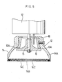
- the bell type rotary atomizing head body may of course be replaced by a dish or disc type rotary atomizing head 201 as shown in Figure 9.
- the rotary atomizing head 201 is provided on the upper surface with a wall 201A for forming the disperse phase liquid into a thin filmy stream. Further, the disperse phase liquid passages 201 B are formed in the vicinity of the outer periphery on the wall 201A.
Landscapes
- Chemical & Material Sciences (AREA)
- Chemical Kinetics & Catalysis (AREA)
- Engineering & Computer Science (AREA)
- Mechanical Engineering (AREA)
- Electrostatic Spraying Apparatus (AREA)
- Processes Of Treating Macromolecular Substances (AREA)
- Processing And Handling Of Plastics And Other Materials For Molding In General (AREA)
- Application Of Or Painting With Fluid Materials (AREA)
- Colloid Chemistry (AREA)
Claims (20)
Applications Claiming Priority (6)
| Application Number | Priority Date | Filing Date | Title |
|---|---|---|---|
| JP129606/81 | 1981-08-19 | ||
| JP56129606A JPS6049016B2 (ja) | 1981-08-19 | 1981-08-19 | 乳化液の製造方法及びその装置 |
| JP3894/82 | 1982-01-13 | ||
| JP57003894A JPS58120638A (ja) | 1981-08-19 | 1982-01-13 | 乳化液の製造方法及びその装置 |
| JP57153590A JPS5942032A (ja) | 1981-08-19 | 1982-09-03 | 乳化液の製造装置 |
| JP57153591A JPS5942033A (ja) | 1981-08-19 | 1982-09-03 | 乳化液の製造装置 |
Publications (2)
| Publication Number | Publication Date |
|---|---|
| EP0072703A1 EP0072703A1 (de) | 1983-02-23 |
| EP0072703B1 true EP0072703B1 (de) | 1985-11-27 |
Family
ID=42060694
Family Applications (1)
| Application Number | Title | Priority Date | Filing Date |
|---|---|---|---|
| EP82304351A Expired EP0072703B1 (de) | 1981-08-19 | 1982-08-18 | Verfahren und Vorrichtung zur Herstellung von Emulsionen |
Country Status (5)
| Country | Link |
|---|---|
| US (1) | US4495086A (de) |
| EP (1) | EP0072703B1 (de) |
| JP (4) | JPS6049016B2 (de) |
| CA (1) | CA1204041A (de) |
| DE (1) | DE3267694D1 (de) |
Families Citing this family (32)
| Publication number | Priority date | Publication date | Assignee | Title |
|---|---|---|---|---|
| JPS61249559A (ja) * | 1985-04-25 | 1986-11-06 | Sumitomo Electric Ind Ltd | 有機薄膜形成方法及び装置 |
| SE452708B (sv) * | 1985-05-23 | 1987-12-14 | Jede Automater Ag | Anordning for beredning och utskenkning av drycker |
| DE3733652A1 (de) * | 1987-10-05 | 1989-04-20 | Abnoba Heilmittel Gmbh | Verfahren und vorrichtung zur herstellung waessriger kolloide |
| JPH0168213U (de) * | 1987-10-23 | 1989-05-02 | ||
| JP2548824B2 (ja) * | 1990-05-25 | 1996-10-30 | カネボウ・エヌエスシー株式会社 | 高軟化点乳化物の製法 |
| EP0485642B1 (de) * | 1990-11-10 | 1995-07-19 | Frisco-Findus Ag | Verfahren und Vorrichtung zum Kochen von Rührei |
| US5478014A (en) * | 1994-04-20 | 1995-12-26 | Hynds; James E. | Method and system for hot air spray coating and atomizing device for use therein |
| US5934574A (en) * | 1995-12-05 | 1999-08-10 | Van Der Steur; Gunnar | Rotary atomizer |
| US6066186A (en) * | 1998-01-02 | 2000-05-23 | Matsumoto; Setsuo | Method of forming and combusting water-in-fuel oil emulsion |
| JP4188623B2 (ja) * | 2002-05-29 | 2008-11-26 | 住友ゴム工業株式会社 | タイヤのパンクシーリング剤の製造方法、及び製造装置 |
| US7351749B2 (en) * | 2002-12-16 | 2008-04-01 | Unilever Home & Personal Care Usa, Division Of Conopco, Inc. | Process for manufacture of personal care products utilizing a concentrate water phase |
| EP1477219A1 (de) * | 2003-05-16 | 2004-11-17 | Tuttle Prilling Systems | Vorrichtung zur Granulierung |
| GB2428569B (en) * | 2005-07-30 | 2009-04-29 | Dyson Technology Ltd | Dryer |
| GB0515754D0 (en) * | 2005-07-30 | 2005-09-07 | Dyson Technology Ltd | Drying apparatus |
| GB0515750D0 (en) * | 2005-07-30 | 2005-09-07 | Dyson Technology Ltd | Drying apparatus |
| GB0515749D0 (en) * | 2005-07-30 | 2005-09-07 | Dyson Technology Ltd | Drying apparatus |
| GB2434094A (en) * | 2006-01-12 | 2007-07-18 | Dyson Technology Ltd | Drying apparatus with sound-absorbing material |
| GB2434095B (en) * | 2006-01-17 | 2011-08-17 | Dyson Technology Ltd | Drying Apparatus |
| BRPI0711837A2 (pt) * | 2006-05-15 | 2011-12-13 | Unilever Nv | processo para preparar uma emulsão |
| RU2313384C1 (ru) * | 2006-05-24 | 2007-12-27 | Станислав Афанасьевич Герасименко | Способ, устройство и установка проведения физико-химических процессов между подвижными средами |
| KR100854775B1 (ko) | 2007-01-15 | 2008-08-27 | 연세대학교 산학협력단 | 촉매필터 제조방법 및 장치 |
| EP2184101A1 (de) * | 2008-11-05 | 2010-05-12 | Urea Casale S.A. | Vibrierender Sprühkondensationsbehälter zum Granulieren einer flüssigen Substanz |
| EP2351779B1 (de) * | 2010-01-27 | 2019-04-24 | Biosphere Medical, Inc. | Mikrokügelchen und Verfahren zur Herstellung der Mikrokügelchen |
| JP5887248B2 (ja) * | 2012-10-17 | 2016-03-16 | 本田技研工業株式会社 | 塗装ガン |
| US11179870B1 (en) * | 2015-05-18 | 2021-11-23 | Trusscore Inc. | Apparatus, methods, and systems for mixing and dispersing a dispersed phase in a medium |
| JP6319233B2 (ja) * | 2015-08-28 | 2018-05-09 | トヨタ自動車株式会社 | 静電微粒化式塗装装置及び塗装方法 |
| JP6985214B2 (ja) * | 2018-06-21 | 2021-12-22 | トヨタ自動車株式会社 | 回転霧化頭および塗装装置 |
| CN110375950B (zh) * | 2019-06-25 | 2020-10-13 | 浙江大学 | 一种颗粒驱动型异重流稳定出流装置 |
| CN110694532B (zh) * | 2019-09-16 | 2022-03-01 | 陕西中医药大学 | 一种药理学实验用的混合加热装置 |
| CN111921403B (zh) * | 2020-08-19 | 2022-01-28 | 山东省食品药品检验研究院 | 一种具有消音减震功能的生物工程用多配料搅拌混合装置 |
| JP7552434B2 (ja) * | 2021-02-26 | 2024-09-18 | トヨタ自動車株式会社 | 静電塗装ハンドガン |
| IT202200027117A1 (it) * | 2022-12-29 | 2024-06-29 | Innovation Polymer Eng Ipe S R L | Miscelatore per materiali polimerici |
Family Cites Families (13)
| Publication number | Priority date | Publication date | Assignee | Title |
|---|---|---|---|---|
| US1295283A (en) * | 1918-11-26 | 1919-02-25 | Fritz Diebold | Process for producing dispersed systems. |
| US1406791A (en) * | 1920-12-06 | 1922-02-14 | Ernest E Werner | Method for producing emulsoids |
| US1668136A (en) * | 1922-03-13 | 1928-05-01 | Agthe Carl Alexander | Production of emulsions |
| US2068136A (en) * | 1934-08-20 | 1937-01-19 | Edwin F Hulbert | Process of preparing emulsions |
| GB764918A (en) * | 1953-05-18 | 1957-01-02 | Henri Eicken | Improvements in or relating to methods and apparatus for producing an emulsion |
| NL272166A (de) * | 1957-09-10 | |||
| US2976175A (en) * | 1958-01-23 | 1961-03-21 | Gen Motors Corp | Method and apparatus for coating electrostatically and mechanically |
| GB862488A (en) * | 1959-07-27 | 1961-03-08 | Kurashiki Rayon Kk | Saponification apparatus and method |
| DE1594655A1 (de) * | 1965-09-21 | 1971-02-04 | Weizenin Dresden Veb | Verfahren zur Herstellung von Emulsionen,insbesondere Wasser-OEl-Emulsionen |
| US3794299A (en) * | 1971-09-23 | 1974-02-26 | Chem Trol Pollution Services | Centrifugal reactor |
| BE790515A (fr) * | 1971-10-25 | 1973-02-15 | Albright & Wilson | Appareil pour melanger ensemble des liquides et des solides en particules |
| GB1597836A (en) * | 1977-09-08 | 1981-09-09 | Nat Res Dev | Producing emulsions |
| DE2850271C3 (de) * | 1978-11-20 | 1981-10-01 | Degussa Ag, 6000 Frankfurt | Vorrichtung zur intensiven Mischung von Flüssigkeiten |
-
1981
- 1981-08-19 JP JP56129606A patent/JPS6049016B2/ja not_active Expired
-
1982
- 1982-01-13 JP JP57003894A patent/JPS58120638A/ja active Pending
- 1982-07-14 US US06/398,441 patent/US4495086A/en not_active Expired - Fee Related
- 1982-07-20 CA CA000407685A patent/CA1204041A/en not_active Expired
- 1982-08-18 EP EP82304351A patent/EP0072703B1/de not_active Expired
- 1982-08-18 DE DE8282304351T patent/DE3267694D1/de not_active Expired
- 1982-09-03 JP JP57153590A patent/JPS5942032A/ja active Pending
- 1982-09-03 JP JP57153591A patent/JPS5942033A/ja active Pending
Also Published As
| Publication number | Publication date |
|---|---|
| US4495086A (en) | 1985-01-22 |
| DE3267694D1 (en) | 1986-01-09 |
| JPS6049016B2 (ja) | 1985-10-30 |
| JPS5830327A (ja) | 1983-02-22 |
| JPS5942032A (ja) | 1984-03-08 |
| EP0072703A1 (de) | 1983-02-23 |
| CA1204041A (en) | 1986-05-06 |
| JPS58120638A (ja) | 1983-07-18 |
| JPS5942033A (ja) | 1984-03-08 |
Similar Documents
| Publication | Publication Date | Title |
|---|---|---|
| US4495086A (en) | Method and apparatus for preparing emulsions | |
| EP0186342B1 (de) | Verfahren und Vorrichtung zum Versprühen eines Beschichtungsmaterials | |
| CA2017779C (en) | Fluid distribution device | |
| US5078321A (en) | Rotary atomizer cup | |
| US4795330A (en) | Apparatus for particles | |
| US4215818A (en) | Induction charging electrostatic spraying device and method | |
| EP2170525B1 (de) | Sprühvorrichtung mit einer parabolflussoberfläche | |
| US2893894A (en) | Method and apparatus for electrostatically coating | |
| US4116163A (en) | Apparatus to coat a flowing mass of particulate material | |
| US4795095A (en) | Rotary atomizer | |
| US5037029A (en) | Centrifugal spraying device with cyclone air flow | |
| US3057558A (en) | Electrostatic atomizing head | |
| AU4309093A (en) | A method and an apparatus for minimizing deposits in a drying chamber | |
| EP0109224A2 (de) | Spritzvorrichtung mit Drehglocke | |
| US4112517A (en) | Mixing apparatus | |
| US20050136190A1 (en) | Coating method and atomizer | |
| JPH0143580B2 (de) | ||
| US3129112A (en) | Electrostatic coating operations | |
| WO1988004895A1 (en) | Apparatus and method for applying a uniform coating to food | |
| EP3583832A1 (de) | Sprühvorrichtung und verfahren zum sprühen von pflanzen | |
| EP0422813B1 (de) | Elektrostatische Sprühvorrichtung für die Beschichtung | |
| US2341536A (en) | Method and apparatus for treating substances | |
| WO1988010152A1 (en) | Spray coating device for electrically conductive coating liquids | |
| JP2003320481A (ja) | 溶接用ワイヤへの潤滑剤塗布方法 | |
| CA2367254C (en) | A spraying method and a spray system for coating liquids |
Legal Events
| Date | Code | Title | Description |
|---|---|---|---|
| PUAI | Public reference made under article 153(3) epc to a published international application that has entered the european phase |
Free format text: ORIGINAL CODE: 0009012 |
|
| AK | Designated contracting states |
Designated state(s): BE CH DE FR GB IT LI NL SE |
|
| 17P | Request for examination filed |
Effective date: 19830812 |
|
| ITF | It: translation for a ep patent filed | ||
| GRAA | (expected) grant |
Free format text: ORIGINAL CODE: 0009210 |
|
| AK | Designated contracting states |
Designated state(s): BE CH DE FR GB IT LI NL SE |
|
| PG25 | Lapsed in a contracting state [announced via postgrant information from national office to epo] |
Ref country code: NL Effective date: 19851127 |
|
| ET | Fr: translation filed | ||
| REF | Corresponds to: |
Ref document number: 3267694 Country of ref document: DE Date of ref document: 19860109 |
|
| NLV1 | Nl: lapsed or annulled due to failure to fulfill the requirements of art. 29p and 29m of the patents act | ||
| PG25 | Lapsed in a contracting state [announced via postgrant information from national office to epo] |
Ref country code: SE Effective date: 19860819 |
|
| PLBE | No opposition filed within time limit |
Free format text: ORIGINAL CODE: 0009261 |
|
| STAA | Information on the status of an ep patent application or granted ep patent |
Free format text: STATUS: NO OPPOSITION FILED WITHIN TIME LIMIT |
|
| 26N | No opposition filed | ||
| BERE | Be: lapsed |
Owner name: RANSBURG JAPAN LTD Effective date: 19860831 |
|
| PG25 | Lapsed in a contracting state [announced via postgrant information from national office to epo] |
Ref country code: LI Effective date: 19870831 Ref country code: CH Effective date: 19870831 |
|
| BERE | Be: lapsed |
Owner name: RANSBURG JAPAN LTD Effective date: 19870831 |
|
| PG25 | Lapsed in a contracting state [announced via postgrant information from national office to epo] |
Ref country code: FR Free format text: LAPSE BECAUSE OF NON-PAYMENT OF DUE FEES Effective date: 19880429 |
|
| REG | Reference to a national code |
Ref country code: CH Ref legal event code: PL |
|
| PG25 | Lapsed in a contracting state [announced via postgrant information from national office to epo] |
Ref country code: DE Effective date: 19880503 |
|
| GBPC | Gb: european patent ceased through non-payment of renewal fee | ||
| REG | Reference to a national code |
Ref country code: FR Ref legal event code: ST |
|
| PG25 | Lapsed in a contracting state [announced via postgrant information from national office to epo] |
Ref country code: GB Free format text: LAPSE BECAUSE OF NON-PAYMENT OF DUE FEES Effective date: 19881121 |
|
| PG25 | Lapsed in a contracting state [announced via postgrant information from national office to epo] |
Ref country code: BE Effective date: 19890831 |
|
| EUG | Se: european patent has lapsed |
Ref document number: 82304351.8 Effective date: 19870812 |