EP0072814B1 - Composants de construction formes d'un materiau durcissable; procede de fabrication d'un tel composant de construction; et procede de production d'un cadre ou structure pour un batiment ou une partie de batiment utilisant un tel materiau de construction - Google Patents
Composants de construction formes d'un materiau durcissable; procede de fabrication d'un tel composant de construction; et procede de production d'un cadre ou structure pour un batiment ou une partie de batiment utilisant un tel materiau de construction Download PDFInfo
- Publication number
- EP0072814B1 EP0072814B1 EP82900407A EP82900407A EP0072814B1 EP 0072814 B1 EP0072814 B1 EP 0072814B1 EP 82900407 A EP82900407 A EP 82900407A EP 82900407 A EP82900407 A EP 82900407A EP 0072814 B1 EP0072814 B1 EP 0072814B1
- Authority
- EP
- European Patent Office
- Prior art keywords
- building
- parts
- reinforcement
- concrete
- building components
- Prior art date
- Legal status (The legal status is an assumption and is not a legal conclusion. Google has not performed a legal analysis and makes no representation as to the accuracy of the status listed.)
- Expired
Links
- 239000000463 material Substances 0.000 title claims description 18
- 238000004519 manufacturing process Methods 0.000 title claims description 10
- 239000004566 building material Substances 0.000 title 1
- 230000002787 reinforcement Effects 0.000 claims abstract description 49
- 239000004567 concrete Substances 0.000 claims abstract description 47
- 238000000034 method Methods 0.000 claims description 21
- 239000004033 plastic Substances 0.000 claims description 6
- 229920003023 plastic Polymers 0.000 claims description 6
- 238000009413 insulation Methods 0.000 claims description 5
- 238000009408 flooring Methods 0.000 claims 1
- XLYOFNOQVPJJNP-UHFFFAOYSA-N water Substances O XLYOFNOQVPJJNP-UHFFFAOYSA-N 0.000 claims 1
- 238000005266 casting Methods 0.000 abstract description 10
- 238000009435 building construction Methods 0.000 abstract description 2
- XEEYBQQBJWHFJM-UHFFFAOYSA-N Iron Chemical compound [Fe] XEEYBQQBJWHFJM-UHFFFAOYSA-N 0.000 description 6
- 229910000831 Steel Inorganic materials 0.000 description 4
- 239000010959 steel Substances 0.000 description 4
- 238000004873 anchoring Methods 0.000 description 3
- 239000011810 insulating material Substances 0.000 description 3
- 229910052742 iron Inorganic materials 0.000 description 3
- 239000011449 brick Substances 0.000 description 2
- 238000005304 joining Methods 0.000 description 2
- 239000002184 metal Substances 0.000 description 2
- 229910052751 metal Inorganic materials 0.000 description 2
- 230000003014 reinforcing effect Effects 0.000 description 2
- 125000006850 spacer group Chemical group 0.000 description 2
- 230000003068 static effect Effects 0.000 description 2
- 239000002131 composite material Substances 0.000 description 1
- 238000010276 construction Methods 0.000 description 1
- 239000006260 foam Substances 0.000 description 1
- 230000004048 modification Effects 0.000 description 1
- 238000012986 modification Methods 0.000 description 1
- 230000000149 penetrating effect Effects 0.000 description 1
- 239000011120 plywood Substances 0.000 description 1
- 238000002360 preparation method Methods 0.000 description 1
- 230000000284 resting effect Effects 0.000 description 1
- 238000007789 sealing Methods 0.000 description 1
- 238000009416 shuttering Methods 0.000 description 1
- 239000000758 substrate Substances 0.000 description 1
- 239000002023 wood Substances 0.000 description 1
Images





Classifications
-
- B—PERFORMING OPERATIONS; TRANSPORTING
- B28—WORKING CEMENT, CLAY, OR STONE
- B28B—SHAPING CLAY OR OTHER CERAMIC COMPOSITIONS; SHAPING SLAG; SHAPING MIXTURES CONTAINING CEMENTITIOUS MATERIAL, e.g. PLASTER
- B28B23/00—Arrangements specially adapted for the production of shaped articles with elements wholly or partly embedded in the moulding material; Production of reinforced objects
- B28B23/02—Arrangements specially adapted for the production of shaped articles with elements wholly or partly embedded in the moulding material; Production of reinforced objects wherein the elements are reinforcing members
- B28B23/028—Arrangements specially adapted for the production of shaped articles with elements wholly or partly embedded in the moulding material; Production of reinforced objects wherein the elements are reinforcing members for double - wall articles
-
- E—FIXED CONSTRUCTIONS
- E04—BUILDING
- E04B—GENERAL BUILDING CONSTRUCTIONS; WALLS, e.g. PARTITIONS; ROOFS; FLOORS; CEILINGS; INSULATION OR OTHER PROTECTION OF BUILDINGS
- E04B1/00—Constructions in general; Structures which are not restricted either to walls, e.g. partitions, or floors or ceilings or roofs
- E04B1/18—Structures comprising elongated load-supporting parts, e.g. columns, girders, skeletons
- E04B1/20—Structures comprising elongated load-supporting parts, e.g. columns, girders, skeletons the supporting parts consisting of concrete, e.g. reinforced concrete, or other stonelike material
- E04B1/21—Connections specially adapted therefor
-
- E—FIXED CONSTRUCTIONS
- E04—BUILDING
- E04C—STRUCTURAL ELEMENTS; BUILDING MATERIALS
- E04C3/00—Structural elongated elements designed for load-supporting
- E04C3/02—Joists; Girders, trusses, or trusslike structures, e.g. prefabricated; Lintels; Transoms; Braces
- E04C3/20—Joists; Girders, trusses, or trusslike structures, e.g. prefabricated; Lintels; Transoms; Braces of concrete or other stone-like material, e.g. with reinforcements or tensioning members
- E04C3/205—Joists; Girders, trusses, or trusslike structures, e.g. prefabricated; Lintels; Transoms; Braces of concrete or other stone-like material, e.g. with reinforcements or tensioning members with apertured web, e.g. frameworks, trusses
-
- E—FIXED CONSTRUCTIONS
- E04—BUILDING
- E04C—STRUCTURAL ELEMENTS; BUILDING MATERIALS
- E04C3/00—Structural elongated elements designed for load-supporting
- E04C3/02—Joists; Girders, trusses, or trusslike structures, e.g. prefabricated; Lintels; Transoms; Braces
- E04C3/29—Joists; Girders, trusses, or trusslike structures, e.g. prefabricated; Lintels; Transoms; Braces built-up from parts of different material, i.e. composite structures
- E04C3/293—Joists; Girders, trusses, or trusslike structures, e.g. prefabricated; Lintels; Transoms; Braces built-up from parts of different material, i.e. composite structures the materials being steel and concrete
-
- E—FIXED CONSTRUCTIONS
- E04—BUILDING
- E04B—GENERAL BUILDING CONSTRUCTIONS; WALLS, e.g. PARTITIONS; ROOFS; FLOORS; CEILINGS; INSULATION OR OTHER PROTECTION OF BUILDINGS
- E04B2/00—Walls, e.g. partitions, for buildings; Wall construction with regard to insulation; Connections specially adapted to walls
- E04B2/74—Removable non-load-bearing partitions; Partitions with a free upper edge
- E04B2/7407—Removable non-load-bearing partitions; Partitions with a free upper edge assembled using frames with infill panels or coverings only; made-up of panels and a support structure incorporating posts
- E04B2/7409—Removable non-load-bearing partitions; Partitions with a free upper edge assembled using frames with infill panels or coverings only; made-up of panels and a support structure incorporating posts special measures for sound or thermal insulation, including fire protection
- E04B2/7412—Posts or frame members specially adapted for reduced sound or heat transmission
Definitions
- the present invention relates to beam-like building components comprising a first beam-part made of a castable and curable material, such as concrete, and having longitudinally extending reinforcement means embedded therein, and a second beam-part which is spaced from the first beam-part and connected thereto by means of a wire-like element extending rearwardly and forwardly i.e. back and forth between said beam-parts.
- the invention also relates to a method for manufacturing such building components, and is also instructive in various usages thereof, for example the use of such building members in constructing frames or structures for a building, or a part of a building, in a simple and ready fashion.
- a beam-like building component of the aforedescribed kind is described and illustrated in DE-C-812 206.
- DE-A-2 929 350 can also be said to describe a building component of the kind mentioned, although in this case it is a question of a concrete slab and not a concrete beam-part connected to a further beam-part via a forwardly and rearwardly extending wire.
- the second beam-part comprises two iron angles welded together to form a T-shaped profile.
- the building component is intended to form part of a floor structure, which also includes other profiled components. The use to which this building component can be put is thus very limited.
- the second beam-part is also made of metal, such as steel, and is welded to the forwardly and rearwardly extending wire. Consequently, this type of building slab also has a very restricted use.
- Other kinds of building components are described, for example, in the published PCT-Application with the number WO 80-01297, which describes a building component comprising two mutually parallel wooden strips, which are joined together with a wire extending rearwardly and forwardly between said strips.
- CH-A-547 927 describes a concrete slab which is joined to a plurality of parallel metal components by means of wire-like elements.
- DE-A-1 784 828 describes three triangularly arranged wooden beams, which are joined together by braces to form a truss or lattice structure.
- US-A-4 125 981 describes a building structure comprising two parallel, composite boards on which concrete is applied, so that the boards are incorporated in the concrete structure.
- the object of the present invention is to provide a lightweight and rigid beam-like building component, whose dimensions can be readily varied in dependence upon prevailing requirements, which is simple to manufacture without requiring complicated equipment therefor, and which finds miscellaneous use within the building field, where said component can be used for both vertical and horizontal members in the erection of building structures.
- the present invention comprises a beam-like building component of the aforementioned kind which is mainly characterized in that the second beam-part is also made of a castable and curable material, such as concrete, having a longitudinally extending reinforcement means embedded therein; and in that the wire-like means extending back and forth between the beam-parts is joined with the longitudinally extending reinforcement means of each beam-part while connecting said beam-parts to form a lightweight, torque-rigid force-absorbing unit provided with integral reinforcement means.
- the back and forth extending wire-like means - which can be said to form a reinforcement spacer means between the beam-parts, determining the width or height of the building component - is statically significant since it connects the longitudinally extending reinforcement means of respective beam-parts together. In this way, it is possible to adjust such beam properties as static bearing capacity, section modulus and moment-absorbing capacity to prevailing requirements in a simple fashion.
- the shape of the beam and its low weight per running meter, coupled with its material, steel and concrete, in static combination enables the beam to be used over a wide field.
- the central vacant space between the beam-parts, in the region of the forwardly and rearwardly extending wire-like means can be put to a number of purposeful uses.
- the space can be used for accommodating the doorframes and windowframes of the building.
- the vacant space can also be used to accommodate insulating material, in which case the building walls will be substantially constantly insulated along the whole of said walls, without the occurrence of thermal bridges.
- a structure erected from building components according to the invention can also be provided with front and back mould walls, enabling concrete to be cast to form a substantially continuous wall or floor structure, the building component in this case being used as a so-called loss mould.
- Building components constructed in accordance with the invention can be used, to advantage, for erecting body structures for such buildings as private houses, low and high rise buildings, schools and industrial buildings.
- the said building components can, in addition, be used to erect other building structures, such as roofs, balconies, baluster etc., in a ready and simple fashion.
- the design of the beam facilitates the application of elements for attaching facade elements, such as bricks or other facade covering elements.
- the two beam-parts comprise the same material, optionally with intermediate parts joining the beam-parts.
- At least one side of the beam-parts is provided with a longitudinally extending wooden strip, which is cast into said beam-part or joined thereto in some other way, and intended to facilitate connection of the beam-part to another building component, by means of nails or screws.
- a method for manufacturing a beam-like, reinforced building component comprising two reinforced beam-parts in spaced apart parallel relationship and made of a castable and curable material, such as concrete, is mainly characterized by introducing into a mould provided with side and end bulkheads and a central, upwardly tapering form body having a height which corresponds approximately to half the thickness of the finished component, a reinforcement ladder or tied-mesh reinforcement which includes a longitudinally extending reinforcement for each beam-part and a reinforcement rod which connects said each beam-part and which extends forwardly and rearwardly between said longitudinally extending reinforcement means; by introducing into the form subsequent hereto a similar, downwardly tapering form body having a height which corresponds approximately to half the thickness of the building component and being anchored relative to the first form body; and by casting concrete or some other curable material into the form and vibrating said form, and permitting the concrete or other curable material to set.
- the method according to the invention does not require any complicated mould or form equipment, and hence building components according to the invention can be manufactured on a factory scale without necessitating high investment costs. Thus, in many instances it may be economically rewarding to arrange for the building components to be manufactured in the immediate vicinity of a building site on which a building is to be erected, the body structure of which building shall comprise building components according to the invention.
- the tied-mesh reinforcement is placed on strips of foamed plastics or like material on the bottom form body, these strips being compressed under the weight of the tied-mesh reinforcement and the upper form body, to form a seal for the cast concrete or like material, so that the central area of the tied-mesh reinforcement is substantially free of concrete.
- the building components can be used as vertical wall supports, horizontal bearing elements and roof trusses, which are joined together by screw joints, and the vacant space between parts of the building components in the region of the central portions of the tied-mesh reinforcement can be used for mounting window frames and door frames and the like between the building components, for drawing electrical conduits, water-supply lines, and for housing insulating material and the like.
- a building component according to the invention has a more or less universal function with a multiplicity of uses.
- the free space between the parts of the building components can be utilized in different ways to facilitate the erection of the building and to make said erection less expensive.
- a beam-like building component 1 comprising a first concrete beam-part 2 provided with a longitudinally extending reinforcement 4, and a second concrete beam-part 3 which extends parallel with said first beam-part 2 and which is provided with a longitudinally extending reinforcement 5.
- a wire-like means 6 Extending forwardly and rearwardly between the beam-parts is a wire-like means 6, which is welded to each of the reinforcements 4 and 5 of respective beam-parts, to join the beam-parts together to form a lightweight, moment-rigid, force-absorbing unit provided with an integral reinforcement.
- the height or thickness of the beam-part can be varied in dependence upon the requirements placed on the building component when used.
- the longitudinally extending reinforcement 4 and 5 in respective beam-parts may also having varying diameter, as can also the forwardly and rearwardly extending reinforcement 6, which serves as a distance-means reinforcement between the beam-parts and thus determines the height of the building component in a horizontal position.
- the building component 1 can be used as a horizontal or vertical structural member when erecting different building frame structures or body structures, and can be connected to other building components through suitable bolt-nut joints.
- the building component can also be joined to other building components by nails or screws, in which case the building component suitably has the form of one of the embodiments illustrated in Figures 1b-1e.
- Each wooden strip 8 can be provided with a waist 8a for anchoring the strips in respective beam-parts when cast therein.
- respective wooden strips can be through-passed by a plurality of transverse steel anchoring pegs (not shown) arranged at a given distance apart, e.g. 400 mm in corresponding beam-parts 2 and 4 respectively.
- each beam-part 2 and 4 has a wooden strip 8 whose width is greater than the corresponding wooden strips illustrated in Figure 1b.
- each beam part 2 and 3 is provided with two longitudinally extending reinforcements 4 and 5 respectively.
- the second beam part has a smaller height and width than the first beam-part 2, which in turn has two wooden strips 8.
- the embodiment according to Figure 1e is similar to the Figure 1c embodiment, insomuch as the two beam-parts 2 and 3 are joined by two forwardly and rearwardly extending reinforcing rods 6. Since, however, one beam-part 3 has smaller dimensions than the other beam-part 2, the reinforcement rods 6 extending between the beam-parts to form spacer means form an angle with each other.
- the beam-part 2 of larger dimensions also has a wooden strip 8 cast therein.
- Figures 1f-1 k illustrate embodiments of beam-like building components according to the invention for use as vertical support or carrying members.
- the embodiments illustrated in Figure 1i and Figure 1j each have an open bottom end, to enable them to be fitted onto a horizontal support beam (see Figure 5).
- the beam-like building members of these two embodiments, and also the embodiment according to 1h, are also open upwardly, for receiving an upper support beam (see Figure 6a).
- Some embodiments for example the embodiments shown in Figures 1g, 1h and 1k, are instead, or in addition, provided with upper and lower closed recesses, for accommodating support beams, which in this case are inserted into the vertical building components laterally.
- Figure 1f illustrates an embodiment of a building component according to the invention provided with an upper and a lower laterally directed recess for co-operation with upper and lower support beams respectively (not shown).
- FIG. 1f illustrates that support or carrying beams constructed in accordance with the invention can be provided with recesses of varying design and of varying locations for co-operation with horizontal support beams, roof trusses or the like.
- Figure 11 illustrates an embodiment of a roof truss comprising two coherently cast beam-like building components according to the invention, said components forming an angle therebetween.
- Figure 1 m illustrates an embodiment of a building component according to the invention for use as a horizontal beam and intended to be assembled together with, for example, one of the support or carrying beams illustrated in Figure 1 f-1 k.
- FIGS 2a-2f The procedural steps taken when manufacturing beam-like building components according to Figure 1a are shown in Figures 2a-2f.
- a simple form 10 having a form bottom 11 which rests on two iron angles 12.
- the vertical sides of the angles are provided with side bulkheads 13, which are pivotally connected to the angles 12 by means of longitudinally extending pivots 14.
- the form is also provided with end bulkheads (not shown).
- an upwardly tapering form body 15 made of steel plate and having a height which corresponds approximately to half the thickness of the finished component.
- two parallel strips 16 of foamed plastics are placed on the form body 15.
- a reinforcement ladder or tied-mesh reinforcement comprising a longitudinally extending reinforcement 4 and 5 and an interconnecting reinforcement rod 6 extending forwardly and rearwardly therebetween is then placed on top of the form body 15.
- a downwardly tapering form body 18 provided with two mutually parallel foam-plastics strips 16 is then placed on the reinforcement 17, the form bodies being anchored by means of a plurality of bolts 19 arranged in suitable spaced relationship, as illustrated in Figure 2d.
- the weight of the upper form body 18 and the reinforcement ladder 17 compresses the foam-plastics strip 16, to form seals which prevent concrete from penetrating into the space between the form bodies, when concrete is poured into the form.
- Figure 2e is a perspective view of the form with a cast building component therein.
- the form and building component can, in this state, be moved, for example on a carriage, to a station where the building component is allowed to harden or set, whereafter the mould is stripped (Figure 2f).
- Building components according to the invention can be manufactured in series by means of the described method, and the illustrated form can be constructed in a rapid and simple manner, with low investment costs for the form equipment.
- the use of a loose bottom-form according to Figure 2 enables it to be removed from the mother form, when the concrete begins to set, thereby enabling the mother form to be cleaned and provided with a new bottom-form for a further casting operation.
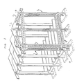
- FIG 3 is a perspective view which illustrates schematically a building body structure erected from building components according to the invention.
- the building components form both vertical wall supports and horizontal support beams, floor structures orso-called ground plates.
- slightly modified building components 1 of approximately the kind illustrated in Figure 11 form roof trusses. These roof trusses can be described as having legs 1 b which extend from a central part 1 a and which form angles with one another.
- Figure 3 also illustrates, among other things, how a simplified foundation can be made with the use of beam-like building components according to the invention.
- a skirting having a height, for example, of 40-50 cm there is used downwardly extending recessed vertical support beams, e.g. according to Figure 1h, at a distance from the level of the ground, said vertical beam being provided with recesses for accommodating a horizontal support beam, e.g. according to Figure 1 m, which supports a floor structure, which may also comprise beams according to Figure 1 m.
- This possibility of producing a simplified foundation structure represents a substantial saving in costs, among other things because the groundwork required is reduced and because no skirting or substrate need be cast.
- the building components can be joined together by bolt-nut joints 25, this being facilitated by the free space in the central part of the building component.
- through-passing holes 1c may also be provided in respective building components, for the passage of bolts.
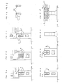
- Figures 4a-4d illustrate schematically an embodiment of a method of building a foundation and of anchoring the bottom part of the frame body structure to basement or foundation slabs.
- this method there is first provided in a ground foundation 20 holes 20a for accommodating skirting foundations, which are reinforced and cast in concrete.
- holders 22 for beam supports in the form of building components 1 are inserted into the cast footings 21, which components are anchored in the manner illustrated in Figure 4b when the concrete sets.
- Figure 4c illustrates a mould side 23 mounted to holders 22. Subsequent to mounting said form side 23, the foundation is filled and packed to the correct height.
- Building components 1 forming vertical wall supports can then be mounted in position and connected to the holders 22 by means of bolts and nuts 25.
- the wall supports carry horizontal building components 1 serving as support beams, which in turn support building components 1 serving as horizontal floor beams or so-called ground plates.
- the horizontal floor beams 1 are joined to the wall supports by means of a bolt and nut joint 25.
- Figure 5 illustrates a modified foundation-laying method, in which some basement slabs 24 are omitted.
- the lower portions of vertical wall supports in the form of building components 1 are instead cast directly into spot footings 21 cast in the ground, whereafter horizontal support beams, also in the form of building components 1, are inserted in recesses in the vertical wall supports.
- Ground plates or a floor structure comprising building components 1 according to the invention are then mounted on the horizontal support beams, said ground plates or floor structure being joined to the vertical wall supports by means of bolt-nut joints 25.
- the structure can then be continued vertically, to build a multi-level building, optionally a so-called high rise building.
- Figure 6a illustrates by way of example a method of installing window frames and door frames in a building body structure.
- Window frames 27 and door frames 28 are secured to vertical stays in the form of building components 1, which are provided with upper and lower recesses which enable said stays to be connected to upper and lower horizontal support beams prior to installing said frames 27 and 28. It will be readily seen that a reliable construction is obtained which enables the vertical position of the window and door frames to be varied in a simple fashion.
- Figure 6b illustrates a method of erecting a multiple-floor building with the use of building components 1 according to the invention.
- Upper load-carrying beams in the form of building components 1 of smaller dimension extend perpendicularly to the plane of the paper, in upper recesses arranged in vertical wall supports, which supports may comprise building components of the kind illustrated in Figure 1i.
- Resting on the load-carrying beams are horizontal beams, for example according to Figure 1m, which form floor structures and which are joined to the vertical support beams by bolt-nut joints 25.
- form boards or shuttering 32 e.g. made of plywood, so-called plyfaform.
- the outer form extends right up to the upper edge of the wall support, while the inner form board extends to a level corresponding to the sealing height of the room.
- the horizontal floor-structure members are also clad on the underside thereof with form material 32, which is also screwed firmly to the said members by means of screw joints 33.
- the space between the form sides is filled with concrete to the level of the lower edge of the upper floor structure.
- the vertical support beams are then placed in position for erecting the following floor - indicated in the upper margin of Figure 6b - in preparation for the next day's casting operation.
- These wall supports are placed on the horizontal load-bearing beams and are screwed thereto and to the beams of the floor structure. Concrete is then poured-in, up to the upper edge of the floor structure.
- the forms are stripped on the following day, and the next floor to be erected is made ready for casting etc.
- the building components 1 located between the form sides 32 will be cast in the concrete wall, and thus form so-called lost moulds.
- Figure 7a illustrates an arrangement for providing compartment recesses for skirting in conjunction with a support beam for a building body structure erected from building components according to the invention.
- a horizontal building component 1 according to the invention is accommodated in the skirting and carries floor-structure members which also comprise building components 1 and which extend perpendicularly.
- Figure 7b illustrates how two support beams in the form of building components 1 are arranged side by side in the skirting, to permit additional loading.
- Figure 7c illustrates a principal method of procedure when applying load-bearing members for facade elements, e.g. bricks.
- load-bearing components 30 of particular design, as illustrated in Figures 7e and 7f.
- these bearing members 30 are hooked onto horizontal support beams 1 accommodated in the skirting, at a given spacing apart.
- Figures 8a-8d illustrate a number of different arrangements of support members against spot- footings and basement slabs respectively (Figure 8a) for beams of long span, where two or more building components 1 are arranged adjacent one another ( Figure 8b), and supports for beams when splicing or joining.
- Figure 8c is a side view of a suitable support element, while Figure 8d illustrates how two horizontal building components are joined or spliced together by means of horizontal splicing or connecting iron 38.
- Figures 9a and 9b illustrate two examples of how a concrete plank is mounted to a building component according to the invention, to produce a so-called lost form.
- Pre-fabricated wall elements 34 in the form of concrete planks or slabs are provided with shoulders 34a defined by an inclined surface corresponding to the slope of respective beam-parts 2.
- the inner wall element 35 which also comprises a concrete plank or slab, is provided with corresponding shoulders 35a.
- shoulders 34a and 35a on the outer and inner walls 34 and 35 respectively is such that when concrete is cast between the outer and inner walls, the pressure exerted by the concrete is transmitted to the building components.
- the wall elements 34, 35 will be anchored to the building components 1 to form a so-called lost form.
- Figure 9b illustrates an arrangement which is a modification of the Figure 9a embodiment and in which the outer and inner walls 34' and 35' respectively exhibit instead mutually abuting surfaces 34'a and 35'a respectively which are straight instead of being inclined.
- the abutment surfaces abut mutually opposed side surfaces of the building component 1.
- the outer and inner walls 34', 35' are anchored to respective building components 1 by means of ties 40.
- the building component 1 exhibits a recess in the region of its central part facilitates concreting of the walls and ensures an improved end result.
- a continuous concrete core along the whole of the wall.
- the space between the outer and inner walls 34, 35 and 34', 35' respectively can be filled with insulating material, thereby to obtain an unbroken insulation in the region of the building element 1, without the presence of thermal bridges.
- the building component need not have the form illustrated in Figure 1, but can be modified in different ways, in which the two beam-parts 2 and 3 along given parts of the building component are joined together and/or form given angles with one another. It is essential with respect to the invention that the building component exhibits two reinforced beam-parts which are joined together by a rearwardly and forwardly extending wire-like means which forms a distance-reinforcement means and which exhibits those properties described above. It will be readily understood to one of normal skill in this art, however, that different types of special members or elements designed for particular purposes can be produced and, independence upon the requirements set, given a form different to the basic form of the building component without departing from the basic concept of the invention.
Landscapes
- Engineering & Computer Science (AREA)
- Architecture (AREA)
- Civil Engineering (AREA)
- Structural Engineering (AREA)
- Chemical & Material Sciences (AREA)
- Ceramic Engineering (AREA)
- Manufacturing & Machinery (AREA)
- Mechanical Engineering (AREA)
- Composite Materials (AREA)
- Physics & Mathematics (AREA)
- Electromagnetism (AREA)
- Rod-Shaped Construction Members (AREA)
- Joining Of Building Structures In Genera (AREA)
Claims (13)
Priority Applications (1)
| Application Number | Priority Date | Filing Date | Title |
|---|---|---|---|
| AT82900407T ATE14465T1 (de) | 1981-02-20 | 1982-02-05 | Balkenaehnliches bauwerksteil aus aushaertendem material; verfahren zur fertigung solch eines bauteils, sowie verfahren zur herstellung eines rahmens oder gefueges fuer ein bauwerk oder bauwerksteil unter nutzung eines solchen baustoffs. |
Applications Claiming Priority (2)
| Application Number | Priority Date | Filing Date | Title |
|---|---|---|---|
| SE8101136A SE436213B (sv) | 1981-02-20 | 1981-02-20 | Balkformat byggelement |
| SE8101136 | 1981-02-20 |
Publications (2)
| Publication Number | Publication Date |
|---|---|
| EP0072814A1 EP0072814A1 (fr) | 1983-03-02 |
| EP0072814B1 true EP0072814B1 (fr) | 1985-07-24 |
Family
ID=20343182
Family Applications (1)
| Application Number | Title | Priority Date | Filing Date |
|---|---|---|---|
| EP82900407A Expired EP0072814B1 (fr) | 1981-02-20 | 1982-02-05 | Composants de construction formes d'un materiau durcissable; procede de fabrication d'un tel composant de construction; et procede de production d'un cadre ou structure pour un batiment ou une partie de batiment utilisant un tel materiau de construction |
Country Status (7)
| Country | Link |
|---|---|
| EP (1) | EP0072814B1 (fr) |
| DE (1) | DE3264811D1 (fr) |
| DK (1) | DK466582A (fr) |
| FI (1) | FI70969C (fr) |
| NO (1) | NO823463L (fr) |
| SE (1) | SE436213B (fr) |
| WO (1) | WO1982002916A1 (fr) |
Families Citing this family (5)
| Publication number | Priority date | Publication date | Assignee | Title |
|---|---|---|---|---|
| SE449887B (sv) * | 1983-12-20 | 1987-05-25 | Axel Bert Roger Ericsson | Balk |
| WO1986004105A1 (fr) * | 1985-01-02 | 1986-07-17 | Per Hofman | Organe de positionnement |
| SE501459C2 (sv) * | 1993-07-19 | 1995-02-20 | George Wegler | Anordning vid balkupplag |
| US7140158B2 (en) * | 2004-07-06 | 2006-11-28 | William Steadman | Composite beam |
| RU178522U1 (ru) * | 2017-08-25 | 2018-04-06 | Общество с ограниченной ответственностью "Юниклинкер" | Сборно-монолитное перекрытие |
Family Cites Families (10)
| Publication number | Priority date | Publication date | Assignee | Title |
|---|---|---|---|---|
| US2112480A (en) * | 1935-09-03 | 1938-03-29 | Reynolds Corp | Joist |
| DE812206C (de) * | 1949-08-25 | 1951-08-27 | Franz Dipl-Ing Wild | Traeger fuer schalungsfrei verlegbare Massivdecken |
| DE816305C (de) * | 1950-08-22 | 1951-10-08 | Franz Dipl-Ing Wild | Stahlbeton-Deckenbalken |
| DE1683860B2 (de) * | 1967-04-05 | 1974-12-12 | Josef 7560 Gaggenau Kaletka | Schalung zur serienmäßigen Fertigung von mindestens einseitig offenen Raumzellen aus Beton, wie Fertiggaragen od.dgl |
| CH547927A (fr) * | 1971-12-08 | 1974-04-11 | Vigarex Ets | Poutre. |
| DE2213433A1 (de) * | 1972-03-20 | 1973-10-04 | August Nolte | Betonformsteinschalungsmauerwerk |
| DE2356288A1 (de) * | 1973-11-10 | 1975-05-15 | Mannesmann Leichtbau Gmbh | Giesskasten zur herstellung von fertigbauteilen, insbesondere von balken aus beton |
| LU77320A1 (fr) * | 1976-05-14 | 1977-08-24 | ||
| US4372093A (en) * | 1978-12-19 | 1983-02-08 | Frelena Ab | Truss of lattice type |
| DE2929350A1 (de) * | 1979-07-20 | 1981-02-12 | Ulrich Dipl Ing Fiergolla | Verbundtraeger fuer gebaeudedecken |
-
1981
- 1981-02-20 SE SE8101136A patent/SE436213B/sv not_active IP Right Cessation
-
1982
- 1982-02-05 DE DE8282900407T patent/DE3264811D1/de not_active Expired
- 1982-02-05 WO PCT/SE1982/000032 patent/WO1982002916A1/fr not_active Ceased
- 1982-02-05 EP EP82900407A patent/EP0072814B1/fr not_active Expired
- 1982-10-18 NO NO823463A patent/NO823463L/no unknown
- 1982-10-19 FI FI823569A patent/FI70969C/fi not_active IP Right Cessation
- 1982-10-20 DK DK466582A patent/DK466582A/da not_active Application Discontinuation
Also Published As
| Publication number | Publication date |
|---|---|
| DK466582A (da) | 1982-10-20 |
| WO1982002916A1 (fr) | 1982-09-02 |
| SE8101136L (sv) | 1982-08-21 |
| FI823569A0 (fi) | 1982-10-19 |
| SE436213B (sv) | 1984-11-19 |
| DE3264811D1 (en) | 1985-08-29 |
| FI70969B (fi) | 1986-07-18 |
| NO823463L (no) | 1982-10-18 |
| FI70969C (fi) | 1986-10-27 |
| EP0072814A1 (fr) | 1983-03-02 |
Similar Documents
| Publication | Publication Date | Title |
|---|---|---|
| US7017316B2 (en) | Concrete panel construction system | |
| US4219978A (en) | Pre-cast reinforced concrete building panel wall structure | |
| US5479749A (en) | Structural systems for supporting a building utilizing light weight steel framing for walls and hollow core concrete slabs for floors | |
| US6260320B1 (en) | Concrete panel construction system | |
| US6301851B1 (en) | Apparatus and method for forming precast modular units and method for constructing precast modular structure | |
| US9399867B2 (en) | Concrete panel corner connection | |
| US20090300999A1 (en) | New type of building, method and means for erecting it | |
| US6280669B2 (en) | Method for making insulated pre-formed wall panels for attachment to like insulated pre-formed wall panels | |
| KR100830241B1 (ko) | 어댑터를 이용한 경량 합성구조 시스템의 상하층 경량합성벽체와 콘크리트 바닥 슬래브의 복합화방법 | |
| KR100830240B1 (ko) | 어댑터를 이용한 경량 합성구조 시스템의 상하층 경량합성벽체와 콘크리트 바닥 슬래브의 복합화방법 | |
| WO1988005484A1 (fr) | Ossature pour murs structuraux dans des constructions a plusieurs etages | |
| EP0183698B1 (fr) | Panneaux de construction | |
| WO1999057387A1 (fr) | Batiment et son procede de construction | |
| FI70969C (fi) | Balkformat byggelement av haerdbart material saett att tillverka detta samt saett att urfoera en ram eller stomme till en byggnad eller del av en saodan med anvaendning av saodana bygelement | |
| RU2017000C1 (ru) | Многоэтажное крупнопанельное здание | |
| AU2002301430B2 (en) | A building construction | |
| CA2311222C (fr) | Systeme de construction de panneaux de beton | |
| AU8008882A (en) | A beam-like building component of curable material;a method of manufacturing such a building component; and a method for producing a frame or structure from such material | |
| JP2545095B2 (ja) | 建築物の基礎部の構造 | |
| KR20250141915A (ko) | 벌집 구조를 가진 판넬 | |
| EP1185748B1 (fr) | Systeme de construction de panneaux en beton | |
| CN87103631A (zh) | 复合建筑物的建筑施工法 | |
| RU1788185C (ru) | Способ восстановлени перекрыти | |
| CN117386035A (zh) | 装配式隔震装置 | |
| WO2006050572A1 (fr) | Appareil et procedes de construction de batiment modulaire |
Legal Events
| Date | Code | Title | Description |
|---|---|---|---|
| PUAI | Public reference made under article 153(3) epc to a published international application that has entered the european phase |
Free format text: ORIGINAL CODE: 0009012 |
|
| AK | Designated contracting states |
Designated state(s): AT BE CH DE FR GB LI LU NL SE |
|
| 17P | Request for examination filed |
Effective date: 19830131 |
|
| GRAA | (expected) grant |
Free format text: ORIGINAL CODE: 0009210 |
|
| AK | Designated contracting states |
Designated state(s): AT BE CH DE FR GB LI LU NL SE |
|
| REF | Corresponds to: |
Ref document number: 14465 Country of ref document: AT Date of ref document: 19850815 Kind code of ref document: T |
|
| REF | Corresponds to: |
Ref document number: 3264811 Country of ref document: DE Date of ref document: 19850829 |
|
| ET | Fr: translation filed | ||
| PG25 | Lapsed in a contracting state [announced via postgrant information from national office to epo] |
Ref country code: LU Free format text: LAPSE BECAUSE OF NON-PAYMENT OF DUE FEES Effective date: 19860228 |
|
| PGFP | Annual fee paid to national office [announced via postgrant information from national office to epo] |
Ref country code: NL Payment date: 19860228 Year of fee payment: 5 |
|
| PGFP | Annual fee paid to national office [announced via postgrant information from national office to epo] |
Ref country code: AT Payment date: 19860526 Year of fee payment: 5 |
|
| PLBE | No opposition filed within time limit |
Free format text: ORIGINAL CODE: 0009261 |
|
| STAA | Information on the status of an ep patent application or granted ep patent |
Free format text: STATUS: NO OPPOSITION FILED WITHIN TIME LIMIT |
|
| 26N | No opposition filed | ||
| PG25 | Lapsed in a contracting state [announced via postgrant information from national office to epo] |
Ref country code: AT Effective date: 19870205 |
|
| PG25 | Lapsed in a contracting state [announced via postgrant information from national office to epo] |
Ref country code: SE Effective date: 19870206 |
|
| PG25 | Lapsed in a contracting state [announced via postgrant information from national office to epo] |
Ref country code: LI Effective date: 19870228 Ref country code: CH Effective date: 19870228 |
|
| BERE | Be: lapsed |
Owner name: HOFMAN PER Effective date: 19870228 |
|
| PG25 | Lapsed in a contracting state [announced via postgrant information from national office to epo] |
Ref country code: NL Effective date: 19870901 |
|
| NLV4 | Nl: lapsed or anulled due to non-payment of the annual fee | ||
| REG | Reference to a national code |
Ref country code: CH Ref legal event code: PL |
|
| PG25 | Lapsed in a contracting state [announced via postgrant information from national office to epo] |
Ref country code: FR Free format text: LAPSE BECAUSE OF NON-PAYMENT OF DUE FEES Effective date: 19881028 |
|
| PG25 | Lapsed in a contracting state [announced via postgrant information from national office to epo] |
Ref country code: DE Effective date: 19881101 |
|
| REG | Reference to a national code |
Ref country code: FR Ref legal event code: ST |
|
| PG25 | Lapsed in a contracting state [announced via postgrant information from national office to epo] |
Ref country code: GB Effective date: 19890205 |
|
| PG25 | Lapsed in a contracting state [announced via postgrant information from national office to epo] |
Ref country code: BE Effective date: 19890228 |
|
| GBPC | Gb: european patent ceased through non-payment of renewal fee | ||
| EUG | Se: european patent has lapsed |
Ref document number: 82900407.6 Effective date: 19880215 |
|
| PGFP | Annual fee paid to national office [announced via postgrant information from national office to epo] |
Ref country code: IE Payment date: 19990524 Year of fee payment: 7 |