EP0072890A2 - Transmission à anneau roulant et dispositif d'inversion - Google Patents
Transmission à anneau roulant et dispositif d'inversion Download PDFInfo
- Publication number
- EP0072890A2 EP0072890A2 EP82103795A EP82103795A EP0072890A2 EP 0072890 A2 EP0072890 A2 EP 0072890A2 EP 82103795 A EP82103795 A EP 82103795A EP 82103795 A EP82103795 A EP 82103795A EP 0072890 A2 EP0072890 A2 EP 0072890A2
- Authority
- EP
- European Patent Office
- Prior art keywords
- ring
- shaft
- rolling ring
- axis
- rolling
- Prior art date
- Legal status (The legal status is an assumption and is not a legal conclusion. Google has not performed a legal analysis and makes no representation as to the accuracy of the status listed.)
- Withdrawn
Links
- 238000005096 rolling process Methods 0.000 title claims abstract description 17
- 230000005540 biological transmission Effects 0.000 title description 7
- 230000033001 locomotion Effects 0.000 claims abstract description 18
- 238000004804 winding Methods 0.000 claims abstract description 6
- 230000001154 acute effect Effects 0.000 abstract description 2
- 230000015572 biosynthetic process Effects 0.000 description 2
- 230000000694 effects Effects 0.000 description 2
- 230000007704 transition Effects 0.000 description 2
- 230000006835 compression Effects 0.000 description 1
- 238000007906 compression Methods 0.000 description 1
- 238000010276 construction Methods 0.000 description 1
- 238000000034 method Methods 0.000 description 1
Images

Classifications
-
- F—MECHANICAL ENGINEERING; LIGHTING; HEATING; WEAPONS; BLASTING
- F16—ENGINEERING ELEMENTS AND UNITS; GENERAL MEASURES FOR PRODUCING AND MAINTAINING EFFECTIVE FUNCTIONING OF MACHINES OR INSTALLATIONS; THERMAL INSULATION IN GENERAL
- F16H—GEARING
- F16H19/00—Gearings comprising essentially only toothed gears or friction members and not capable of conveying indefinitely-continuing rotary motion
- F16H19/02—Gearings comprising essentially only toothed gears or friction members and not capable of conveying indefinitely-continuing rotary motion for interconverting rotary or oscillating motion and reciprocating motion
- F16H19/025—Gearings comprising essentially only toothed gears or friction members and not capable of conveying indefinitely-continuing rotary motion for interconverting rotary or oscillating motion and reciprocating motion comprising a friction shaft
Definitions
- the invention relates to a rolling ring gear for converting a rotary movement into a reciprocating movement. Furthermore, the invention relates to a traversing device for winding machines, which is equipped with a rolling ring gear.
- a rolling ring gear in which at least one ring body, the inner surface of which is spherical, with this inner surface is in frictional engagement with the outer surface of a shaft.
- the ring axis When the ring axis is inclined, the ring rolls obliquely on the surface of the rotating shaft and consequently carries out a translational movement in the direction of the shaft axis.
- the inclination is determined by the fact that the rotating ring with ball bearings is mounted in an inclined, non-rotating ring.
- a lever with an over-dead center spring mechanism can reverse the movement at two stops. so that a back and forth movement arises.
- the rolling element - be it a ring or a roller - needs a bearing that holds it in a certain angular position. If you want to generate a back and forth movement, additional adjustment means are required for the storage, which cause the storage to flip over at the reversal points and thus a reversal of movement.
- the inventor has set himself the task of creating a rolling ring gear with a particularly simple construction and a very small mass carried along.
- the inventor has set himself the special task of creating a traversing device for winding machines using such a rolling ring gear.
- the first part of the task is solved by the combination of features specified in claim 1.
- the advantage of the transmission according to the invention is that the reciprocating part consists of only a single ring, which does not require storage or an additional adjusting means to effect the reversal of movement.
- the second part of the task is solved by the feature specified in claim 2.
- the feature of claim 3 enables the automatic trapping of a thread.
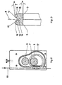
- the two smooth shafts 2, 3 are mounted parallel to each other with a short distance.
- the shaft 2 is provided with an elongated pin 4 which is connected to a drive, not shown.
- the bearings of the shaft 3 are displaceable relative to the bearings of the shaft 2 at right angles to the shaft axes. They are held in the rest position shown by means of screws 5 adjustable compression springs 6.
- a ring 7 sits on the shaft 2. Its inside diameter is almost one and a half times the diameter of the shaft 2.
- the inner and the outer surface of the ring 7 are mirror-symmetrical with respect to the central plane 8.
- the inner surface consists of two zones which are slightly conically widened outwards from the central plane 8 and which form the running surfaces 9.
- the angle ⁇ determining the cone is approximately 3 ° 30 minutes in the embodiment shown in FIG. 3.
- the outer surface of the ring 7 has a narrow zone on both sides of the central plane 8, which forms the running surface 10 and is also slightly conically widened outwards.
- the described design of the inner and outer surface of the ring has the effect that the ring clamped between the two shafts 2, 3 under the pressure of the springs 6 assumes a position in which its axis encloses an acute angle with the axis of the shaft 2.
- the size of the angle depends on the angle Ot. Because of the mirror-symmetrical off Formation of the surfaces of the ring 7 there are two mutually symmetrical such positions. In these two positions, the distance between the two shaft axes has the smallest possible value. Therefore these positions are stable equilibrium positions. In one of these two positions, the ring 7 adjusts itself automatically.
- the ring 7 rolls on it and in turn sets the shaft 3 in rotation. Because of the inclined position, the rolling motion has a component in the axial direction of the shaft 2, similar to a screw. Accordingly, the ring moves e.g. in the direction of the arrow 11. In the vicinity of the two shaft ends, stops 12, 13 are attached, in each case on the side of the shaft 2 on which the side 7a of the ring 7 which leads in the direction of movement due to the inclined position lies. When the ring 7 abuts the stop 12 with its leading side, the retracting side 7b of the ring moves further forward due to the inertia.
- the ring 7 folds over and jumps into its other equilibrium position, in which the axial component of its rolling motion has the opposite direction.
- the ring therefore moves with the direction of rotation of the drive unchanged now in the opposite direction until it reaches the other stop 13. There is a corresponding reversal of movement there in a corresponding manner.
- a traversing device is shown in section in FIG. 2.
- the transmission is basically constructed as described in connection with FIG. 1.
- a housing 17 is provided for shielding the shafts 2, 3 against any loose threads, which encloses the transmission over its entire length except for a longitudinal slot from which a segment of the ring 7 protrudes.
- Lifting the thread 18 out of the groove 14 is favored by the beveled transition zones 15.
- the thread comes back into the traversing area, it slides up the spherical edge zone 16 and automatically jumps back into the groove.
Landscapes
- Engineering & Computer Science (AREA)
- General Engineering & Computer Science (AREA)
- Mechanical Engineering (AREA)
- Transmission Devices (AREA)
- Winding Filamentary Materials (AREA)
- Winding Of Webs (AREA)
Applications Claiming Priority (2)
| Application Number | Priority Date | Filing Date | Title |
|---|---|---|---|
| DE19813132854 DE3132854A1 (de) | 1981-08-20 | 1981-08-20 | Waelzringgetriebe und changiereinrichtung |
| DE3132854 | 1981-08-20 |
Publications (2)
| Publication Number | Publication Date |
|---|---|
| EP0072890A2 true EP0072890A2 (fr) | 1983-03-02 |
| EP0072890A3 EP0072890A3 (fr) | 1984-08-08 |
Family
ID=6139677
Family Applications (1)
| Application Number | Title | Priority Date | Filing Date |
|---|---|---|---|
| EP82103795A Withdrawn EP0072890A3 (fr) | 1981-08-20 | 1982-05-04 | Transmission à anneau roulant et dispositif d'inversion |
Country Status (3)
| Country | Link |
|---|---|
| EP (1) | EP0072890A3 (fr) |
| JP (1) | JPS5891955A (fr) |
| DE (1) | DE3132854A1 (fr) |
Cited By (1)
| Publication number | Priority date | Publication date | Assignee | Title |
|---|---|---|---|---|
| CN112456237A (zh) * | 2020-12-28 | 2021-03-09 | 山东兴恒电机有限公司 | 一种用于纺织机械的过线装置 |
Family Cites Families (5)
| Publication number | Priority date | Publication date | Assignee | Title |
|---|---|---|---|---|
| NL81939C (fr) * | 1953-08-12 | |||
| DE1057411B (de) * | 1954-07-02 | 1959-05-14 | Uhing Joachim Ing | Reibungsgetriebe zur Umwandlung einer Drehbewegung in eine Vorschubbewegung |
| US2940322A (en) * | 1956-04-19 | 1960-06-14 | Uhing Joachim | Rotary translatory motion drive gear |
| DE1203379B (de) * | 1960-08-09 | 1965-10-21 | Deutsche Bundespost | Synchronmotor |
| US3259336A (en) * | 1964-04-08 | 1966-07-05 | Automation Machines & Equipmen | Coil winding machine |
-
1981
- 1981-08-20 DE DE19813132854 patent/DE3132854A1/de not_active Withdrawn
-
1982
- 1982-05-04 EP EP82103795A patent/EP0072890A3/fr not_active Withdrawn
- 1982-08-20 JP JP14456882A patent/JPS5891955A/ja active Granted
Cited By (1)
| Publication number | Priority date | Publication date | Assignee | Title |
|---|---|---|---|---|
| CN112456237A (zh) * | 2020-12-28 | 2021-03-09 | 山东兴恒电机有限公司 | 一种用于纺织机械的过线装置 |
Also Published As
| Publication number | Publication date |
|---|---|
| EP0072890A3 (fr) | 1984-08-08 |
| DE3132854A1 (de) | 1983-03-03 |
| JPS5891955A (ja) | 1983-06-01 |
| JPS6220418B2 (fr) | 1987-05-07 |
Similar Documents
| Publication | Publication Date | Title |
|---|---|---|
| EP0320621A1 (fr) | Dispositif pour convertir un mouvement rotatif en un mouvement axial | |
| DE3035234C2 (de) | Vorrichtung zum Herstellen eines Wellenrohrkompensators aus einem kreiszylindrischen Blechrohrabschnitt | |
| DE1685905C3 (de) | Offenendspinnvorrichtung mit einem in der einen oder der entgegengesetzten Drehrichtung antreibbaren Spinnrotor | |
| DE19536761A1 (de) | Kehrgewindeantrieb für Fadenführer einer Spuleinrichtung | |
| DE3345237A1 (de) | Aufspulmaschine | |
| EP0072890A2 (fr) | Transmission à anneau roulant et dispositif d'inversion | |
| DE3345420C2 (fr) | ||
| DE1132773B (de) | Kegelrollen-Reibungsgetriebe | |
| DE3323512A1 (de) | Gelenkkupplungsanordnung zur bildung eines ungleichfoermigkeitsgetriebes, insbesondere zum antrieb einer fenstermesserwalze in einer briefhuellenherstellungsmaschine | |
| DE3231352C1 (de) | Vorrichtung zur Umwandlung einer geradlinigen Bewegung in eine Drehbewegung | |
| DE960144C (de) | Elektromechanisch gesteuerter Plandrehkopf | |
| EP4126727B1 (fr) | Dispositif de pose d'un fil | |
| DE19823352C2 (de) | Miniaturisierte Linearantriebsvorrichtung | |
| DE2624734A1 (de) | Gewindeschneideinrichtung mit selbsttaetiger tiefensteuerung | |
| DE2052768A1 (de) | Vorrichtung zum Abziehen und Weiterge ben von Draht in Drahtziehmaschinen | |
| DE2424577C2 (de) | Schaltvorrichtung für stufenlos einstellbare Schaltwerksgetriebe, insbesondere für Kraftfahrzeuge | |
| DE506321C (de) | Kinematograph mit ununterbrochen bewegtem Bildband | |
| DE7527213U (de) | Vorrichtung zum hin- und herfuehren eines fadens im zuge des aufwickelns auf eine fadenspule | |
| DE1090515B (de) | Stativpanoramaeinrichtung mit Stabilisierungsgetriebe fuer Filmkameras | |
| DE2931067A1 (de) | Motorgetriebe fuer waschmaschinen | |
| DE2932242A1 (de) | Vorrichtung zur fachbildung bei webstuehlen | |
| DE626641C (de) | Streifenziehvorrichtung mit einer Tellerkupplung | |
| AT241221B (de) | Kugelreibungsgetriebe | |
| DE2030995C3 (de) | Antriebseinrichtung für das über einen Kurbeltrieb linear hin- und herbewegte Walzgerüst eines Pilgerschrittwalzwerkes | |
| DE2153023A1 (de) | Linearer reibantrieb mittels kugelumlaufmutter |
Legal Events
| Date | Code | Title | Description |
|---|---|---|---|
| PUAI | Public reference made under article 153(3) epc to a published international application that has entered the european phase |
Free format text: ORIGINAL CODE: 0009012 |
|
| AK | Designated contracting states |
Designated state(s): BE CH DE FR GB IT LI NL |
|
| PUAL | Search report despatched |
Free format text: ORIGINAL CODE: 0009013 |
|
| AK | Designated contracting states |
Designated state(s): BE CH DE FR GB IT LI NL |
|
| STAA | Information on the status of an ep patent application or granted ep patent |
Free format text: STATUS: THE APPLICATION IS DEEMED TO BE WITHDRAWN |
|
| 18D | Application deemed to be withdrawn |
Effective date: 19841201 |
|
| RIN1 | Information on inventor provided before grant (corrected) |
Inventor name: BLOECKER, FRANZ |