EP0072909A2 - Verfahren zur Herstellung einer Zwischenlage aus Metall - Google Patents
Verfahren zur Herstellung einer Zwischenlage aus Metall Download PDFInfo
- Publication number
- EP0072909A2 EP0072909A2 EP82106244A EP82106244A EP0072909A2 EP 0072909 A2 EP0072909 A2 EP 0072909A2 EP 82106244 A EP82106244 A EP 82106244A EP 82106244 A EP82106244 A EP 82106244A EP 0072909 A2 EP0072909 A2 EP 0072909A2
- Authority
- EP
- European Patent Office
- Prior art keywords
- suspension
- intermediate layer
- metal powder
- pressing
- pressing surface
- Prior art date
- Legal status (The legal status is an assumption and is not a legal conclusion. Google has not performed a legal analysis and makes no representation as to the accuracy of the status listed.)
- Granted
Links
- 229910052751 metal Inorganic materials 0.000 title claims abstract description 26
- 239000002184 metal Substances 0.000 title claims abstract description 26
- 238000004519 manufacturing process Methods 0.000 title claims description 8
- 238000000034 method Methods 0.000 title claims description 5
- 238000003825 pressing Methods 0.000 claims abstract description 26
- 239000000725 suspension Substances 0.000 claims abstract description 22
- 239000000843 powder Substances 0.000 claims abstract description 13
- PXHVJJICTQNCMI-UHFFFAOYSA-N Nickel Chemical compound [Ni] PXHVJJICTQNCMI-UHFFFAOYSA-N 0.000 claims abstract description 6
- 238000000576 coating method Methods 0.000 claims abstract description 6
- 239000011248 coating agent Substances 0.000 claims abstract description 5
- RTAQQCXQSZGOHL-UHFFFAOYSA-N Titanium Chemical compound [Ti] RTAQQCXQSZGOHL-UHFFFAOYSA-N 0.000 claims abstract description 3
- 229910052759 nickel Inorganic materials 0.000 claims abstract description 3
- 229910052719 titanium Inorganic materials 0.000 claims abstract description 3
- 239000010936 titanium Substances 0.000 claims abstract description 3
- BASFCYQUMIYNBI-UHFFFAOYSA-N platinum Chemical compound [Pt] BASFCYQUMIYNBI-UHFFFAOYSA-N 0.000 claims abstract 4
- 238000010438 heat treatment Methods 0.000 claims abstract 3
- 239000000969 carrier Substances 0.000 claims abstract 2
- 229910052697 platinum Inorganic materials 0.000 claims abstract 2
- 150000002739 metals Chemical class 0.000 claims description 6
- 229910010293 ceramic material Inorganic materials 0.000 claims description 4
- 239000004922 lacquer Substances 0.000 claims description 4
- 239000000203 mixture Substances 0.000 claims description 3
- RSWGJHLUYNHPMX-UHFFFAOYSA-N Abietic-Saeure Natural products C12CCC(C(C)C)=CC2=CCC2C1(C)CCCC2(C)C(O)=O RSWGJHLUYNHPMX-UHFFFAOYSA-N 0.000 claims description 2
- KHPCPRHQVVSZAH-HUOMCSJISA-N Rosin Natural products O(C/C=C/c1ccccc1)[C@H]1[C@H](O)[C@@H](O)[C@@H](O)[C@@H](CO)O1 KHPCPRHQVVSZAH-HUOMCSJISA-N 0.000 claims description 2
- 230000003647 oxidation Effects 0.000 claims description 2
- 238000007254 oxidation reaction Methods 0.000 claims description 2
- 230000001603 reducing effect Effects 0.000 claims description 2
- KHPCPRHQVVSZAH-UHFFFAOYSA-N trans-cinnamyl beta-D-glucopyranoside Natural products OC1C(O)C(O)C(CO)OC1OCC=CC1=CC=CC=C1 KHPCPRHQVVSZAH-UHFFFAOYSA-N 0.000 claims description 2
- 230000001681 protective effect Effects 0.000 claims 3
- 238000001035 drying Methods 0.000 claims 2
- 239000007788 liquid Substances 0.000 claims 2
- VYZAMTAEIAYCRO-UHFFFAOYSA-N Chromium Chemical compound [Cr] VYZAMTAEIAYCRO-UHFFFAOYSA-N 0.000 claims 1
- RYGMFSIKBFXOCR-UHFFFAOYSA-N Copper Chemical compound [Cu] RYGMFSIKBFXOCR-UHFFFAOYSA-N 0.000 claims 1
- LFQSCWFLJHTTHZ-UHFFFAOYSA-N Ethanol Chemical compound CCO LFQSCWFLJHTTHZ-UHFFFAOYSA-N 0.000 claims 1
- FYYHWMGAXLPEAU-UHFFFAOYSA-N Magnesium Chemical compound [Mg] FYYHWMGAXLPEAU-UHFFFAOYSA-N 0.000 claims 1
- HCHKCACWOHOZIP-UHFFFAOYSA-N Zinc Chemical compound [Zn] HCHKCACWOHOZIP-UHFFFAOYSA-N 0.000 claims 1
- 229910052804 chromium Inorganic materials 0.000 claims 1
- 239000011651 chromium Substances 0.000 claims 1
- 229910052802 copper Inorganic materials 0.000 claims 1
- 239000010949 copper Substances 0.000 claims 1
- 229910052749 magnesium Inorganic materials 0.000 claims 1
- 239000011777 magnesium Substances 0.000 claims 1
- 238000002844 melting Methods 0.000 claims 1
- 230000008018 melting Effects 0.000 claims 1
- 125000000449 nitro group Chemical group [O-][N+](*)=O 0.000 claims 1
- 239000011347 resin Substances 0.000 claims 1
- 229920005989 resin Polymers 0.000 claims 1
- 229910052715 tantalum Inorganic materials 0.000 claims 1
- GUVRBAGPIYLISA-UHFFFAOYSA-N tantalum atom Chemical compound [Ta] GUVRBAGPIYLISA-UHFFFAOYSA-N 0.000 claims 1
- 229910052725 zinc Inorganic materials 0.000 claims 1
- 239000011701 zinc Substances 0.000 claims 1
- 239000000919 ceramic Substances 0.000 abstract description 9
- 239000003973 paint Substances 0.000 abstract description 3
- 230000035882 stress Effects 0.000 description 5
- 239000012530 fluid Substances 0.000 description 3
- 239000000470 constituent Substances 0.000 description 2
- 239000011888 foil Substances 0.000 description 2
- 238000003780 insertion Methods 0.000 description 2
- 230000037431 insertion Effects 0.000 description 2
- 238000005304 joining Methods 0.000 description 2
- 230000001590 oxidative effect Effects 0.000 description 2
- 239000007787 solid Substances 0.000 description 2
- 229910052581 Si3N4 Inorganic materials 0.000 description 1
- 230000001154 acute effect Effects 0.000 description 1
- 230000007423 decrease Effects 0.000 description 1
- 239000008187 granular material Substances 0.000 description 1
- 238000009434 installation Methods 0.000 description 1
- HQVNEWCFYHHQES-UHFFFAOYSA-N silicon nitride Chemical compound N12[Si]34N5[Si]62N3[Si]51N64 HQVNEWCFYHHQES-UHFFFAOYSA-N 0.000 description 1
- 239000002904 solvent Substances 0.000 description 1
- 230000008646 thermal stress Effects 0.000 description 1
Images
Classifications
-
- F—MECHANICAL ENGINEERING; LIGHTING; HEATING; WEAPONS; BLASTING
- F01—MACHINES OR ENGINES IN GENERAL; ENGINE PLANTS IN GENERAL; STEAM ENGINES
- F01D—NON-POSITIVE DISPLACEMENT MACHINES OR ENGINES, e.g. STEAM TURBINES
- F01D5/00—Blades; Blade-carrying members; Heating, heat-insulating, cooling or antivibration means on the blades or the members
- F01D5/30—Fixing blades to rotors; Blade roots ; Blade spacers
- F01D5/3084—Fixing blades to rotors; Blade roots ; Blade spacers the blades being made of ceramics
-
- B—PERFORMING OPERATIONS; TRANSPORTING
- B22—CASTING; POWDER METALLURGY
- B22F—WORKING METALLIC POWDER; MANUFACTURE OF ARTICLES FROM METALLIC POWDER; MAKING METALLIC POWDER; APPARATUS OR DEVICES SPECIALLY ADAPTED FOR METALLIC POWDER
- B22F7/00—Manufacture of composite layers, workpieces, or articles, comprising metallic powder, by sintering the powder, with or without compacting wherein at least one part is obtained by sintering or compression
- B22F7/06—Manufacture of composite layers, workpieces, or articles, comprising metallic powder, by sintering the powder, with or without compacting wherein at least one part is obtained by sintering or compression of composite workpieces or articles from parts, e.g. to form tipped tools
- B22F7/062—Manufacture of composite layers, workpieces, or articles, comprising metallic powder, by sintering the powder, with or without compacting wherein at least one part is obtained by sintering or compression of composite workpieces or articles from parts, e.g. to form tipped tools involving the connection or repairing of preformed parts
- B22F7/064—Manufacture of composite layers, workpieces, or articles, comprising metallic powder, by sintering the powder, with or without compacting wherein at least one part is obtained by sintering or compression of composite workpieces or articles from parts, e.g. to form tipped tools involving the connection or repairing of preformed parts using an intermediate powder layer
-
- F—MECHANICAL ENGINEERING; LIGHTING; HEATING; WEAPONS; BLASTING
- F01—MACHINES OR ENGINES IN GENERAL; ENGINE PLANTS IN GENERAL; STEAM ENGINES
- F01D—NON-POSITIVE DISPLACEMENT MACHINES OR ENGINES, e.g. STEAM TURBINES
- F01D5/00—Blades; Blade-carrying members; Heating, heat-insulating, cooling or antivibration means on the blades or the members
- F01D5/30—Fixing blades to rotors; Blade roots ; Blade spacers
- F01D5/3092—Protective layers between blade root and rotor disc surfaces, e.g. anti-friction layers
-
- B—PERFORMING OPERATIONS; TRANSPORTING
- B22—CASTING; POWDER METALLURGY
- B22F—WORKING METALLIC POWDER; MANUFACTURE OF ARTICLES FROM METALLIC POWDER; MAKING METALLIC POWDER; APPARATUS OR DEVICES SPECIALLY ADAPTED FOR METALLIC POWDER
- B22F2998/00—Supplementary information concerning processes or compositions relating to powder metallurgy
Definitions
- the invention relates to an intermediate layer according to the preamble of claim 1.
- the invention further relates to methods for producing the intermediate layer according to the invention.
- the rotor blades including their feet, or additionally the rotor disk made of ceramic material.
- One of the main problems is the connection of the ceramic blade, i.e. of her ceramic foot, too, with the rotor disc, i.e. So in the blade attachment.
- the types of said groove are known, i.e.
- the groove generally runs in its longitudinal direction either as a single groove for a foot parallel to the rotor axis or obliquely as in the case of a helical gear or coaxially as an annular groove for all blades or feet of the blade ring.
- the foot is usually dovetail-shaped or pine-cone-shaped in a cut perpendicular to the longitudinal and insertion direction of the groove in such a way that the above-mentioned, generally planar wings (bearing surfaces) of the foot and the groove, which in this cut have the same shape has, like the foot and into which it is inserted, lie at an acute angle to the rotor-radial foot median plane running in that direction. This flank angle is generally 30 to 75 °. As a result, the wings are pressed obliquely when the centrifugal forces of the rotor blade act.
- a major difficulty lies in the fact that the brittle, non-plastically deformable ceramic blade, ie its foot or its wings, does not lie or rest along the groove on the wings thereof, which is due to inevitable manufacturing inaccuracies thing is. This often leads to local stress increases, which reduces the breaking speed or the permissible centrifugal load on the blade.
- One way to reduce or eliminate this disadvantage is to insert a metal foil between the wings.
- This film by being plastically deformed, at least largely compensates for the manufacturing inaccuracies mentioned and ensures an at least reasonably uniform introduction of force, so that a higher breaking speed or the like and a longer service life can be achieved for the blade.
- the film reduces the friction between the foot and the groove, so that the risk is reduced that the blade or its foot is jammed in the groove by temperature changes and experiences additional stress.
- the rotor disc becomes hot during operation, which causes the groove to widen and the blade to move radially outwards, and when it cools, the blade, if the foil is not provided, does not go back due to the friction and the groove width decreases and exerts additional tension on the shovel or its foot.
- the object of the invention is to reduce or eliminate these disadvantages and. is solved according to the invention by the characterizing part of claim 1.
- the covering according to the invention builds up or the two coverings according to the invention reduce stress peaks better because this covering or these coverings is more easily deformable than the film by the pressing of the pressing surfaces. Furthermore, the covering or the coverings can be produced with little effort, and the covering adheres firmly to the pressing surface or the two pressing surfaces or the coverings adhere firmly to the two pressing surfaces.
- the covering or the coverings take the place of the film, so that there is no longer any installation difficulty with a small shovel or small foot. There is also no more slipping of the film.
- the metal powder suspension mentioned in the invention is applied to the pressing surface or surfaces, where it dries up.
- a solid portion of the non-metallic component of the suspension can escape, and the coating then remains. It consists of the metal of the metal powder.
- the metal powder granules have an average grain size of in particular 0.1 ⁇ m to 54 ⁇ m.
- the invention is generally applied when the pressing or joining point is exposed to thermal stress in addition to the pressing surface pressure.
- the invention can also be advantageously used when the Press or joint is under pressure of a fluid; the pressing or joining point is generally better sealed with the covering or coverings according to the invention than with the film.
- the intermediate layer according to the invention is particularly hooked on pressing surfaces, engaging behind or the like. applied to the blade attachments mentioned, where the pressing by pulling then takes place, in these blade attachments by the blade centrifugal force. But it can also e.g. can be used against each other without snagging.
- the metals or metal mixtures mentioned in claim 2 are the preferred. Which metal or which metal mixture is chosen depends on the operating temperature of the press or joint to be provided with the covering. Regarding the non-metallic constituent of the suspension, claims 3 are generally followed. Furthermore, the suspension is usually thin. Furthermore, the suspension can be applied easily. It is often brushed on.
- the non-metallic component of the suspension must not have an oxidizing effect on the metal powder when heated.
- a reducing effect e.g. with the rosin.
- the intermediate layer e.g. proceeded according to claim 4, but preferably according to claim 5.
- the capillary forces mentioned in claim 5 bring about a complete filling of the space with the suspension. If one proceeds according to claim 5, manufacturing inaccuracies are largely compensated for even without plastic deformation of the covering, as a result of which stress peaks are reduced particularly effectively. If the procedure is as claimed in claim 7, a coating is formed which largely resists oxidation. Metals oxidizing in air are e.g. Nickel or titanium.
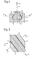
- the direction mentioned is designated by 10, the middle plane mentioned by 11.
- the direction 10 runs - see FIG. 2 - obliquely to the circumferential direction - arrow 17 - of the rotor disk 13.
- the ceramic base 15 of the ceramic axial vane and the associated groove 18 of the metallic rotor disk 13 together with two shown exaggeratedly thick for better visibility, metallic intermediate linings 14 said axial blade attachment.
- At the foot 15 there is a broken waist-like waiter gear part 16 and on this, which is not shown, a blade platform and the blade on; the SchaufeY D consists of all these parts in one piece.
- wing 19 is somewhat narrower than the wing 20 and is located at full load of the axial gas turbine as shown in Fig. 1 on both sides at a small distance from the longitudinal edges of the wings 20.
- a metal powder suspension with a paint as non-metallic constituent is brushed on the outside of the space between the wings 19 and 20 on the long side 23 thereof, and the capillary forces completely fill this space with this suspension.
- the fill is air dried, i.e. the solvent of the paint evaporates.
- the dried fill is then heated by the fluid flowing into the bladed flow space, so that the solid portion of the lacquer escapes.
- the intermediate covering 14 adheres firmly to the wings 19 and 20.
Landscapes
- Engineering & Computer Science (AREA)
- Mechanical Engineering (AREA)
- Chemical & Material Sciences (AREA)
- General Engineering & Computer Science (AREA)
- Ceramic Engineering (AREA)
- Composite Materials (AREA)
- Manufacturing & Machinery (AREA)
- Materials Engineering (AREA)
- Turbine Rotor Nozzle Sealing (AREA)
- Structures Of Non-Positive Displacement Pumps (AREA)
Abstract
Description
- Die Erfindung bezieht sich auf eine Zwischenlage gemäß dem Oberbegriff des Anspruchs 1. Die Erfindung bezieht sich ferner auf Verfahren zur Herstellung der erfindungsgemäßen Zwischenlage.
- Die Problematik im Zusammenhang mit der Erfindung wird im folgenden bei der in diesem Oberbegriff bevorzugt angegebenen Axiallaufschaufelbefestigung dargelegt, ist jedoch auch allgemein vorhanden, wenn zumindest einer der beiden Preßflächenträger wenigstens im Preßflächenbereich, einschließlich Preßfläche, aus keramischem Werkstoff besteht.
- Bei hohen Temperaturen des Fluids im beschaufelten Strömungskanal wünscht man sich oft die Laufschaufeln, einschließlich ihrer Füße, oder zusätzlich die Läuferscheibe aus keramischem Werkstoff. Eines der Hauptprobleme liegt dabei in der Verbindung der Keramikschaufel, d.h. ihres also auch keramischen Fußes, mit der Läuferscheibe, d.h. also in der Schaufelbefestigung.
- Die Arten der genannten Nut sind bekannt, d.h. die Nut verläuft in ihrer Längsrichtung im allgemeinen entweder als Einzelnut für einen Fuß parallel zur Läuferachse oder schräg wie bei einem Schrägzahnstirnrad oder koaxial als Ringnut für sämtliche Schaufeln bzw. Füße des Schaufelkranzes. Wegen des keramischem Werkstoffs ist der Fuß in einem zur Nutlängs- und Fußeinschiebrichtung senkrechten Schnitt meist schwalbenschwanz- oder tannenzapfenförmig in der Art, daß die genannten, im allgemeinen ebenen Tragflächen (tragenden Flächen) des Fußes und der Nut, die in diesem Schnitt die gleiche Form hat wie der Fuß und in die dieser eingeschoben ist, unter einem spitzen Winkel zu-der in jener Richtung verlaufenden, läuferradialen Fuß-Mittelebene liegen. Dieser Flankenwinkel beträgt im allgemeinen 30 bis 75°. Dadurch sind übrigens die Tragflächen beim Wirken der Zentrifugalkräfte der Laufschaufel schräg gepreßt.
- Im Fußbereich treten die höchsten mechanischen Belastungen der Laufschaufel im Betrieb durch die die Pressung der Tragflächen hervorrufende Fliehkraft der Laufschaufel auf, so daß die Belastbarkeit sogar hochfester Keramiken, wie z.B. von heißgepreßtem Siliziumnitrid (Si3N4), weitgehend ausgenutzt wird bzw. teilweise nicht ausreicht.
- Eine Hauptschwierigkeit liegt darin, daß die spröde, nicht plastisch verformbare Keramikschaufel, d.h. ihr Fuß bzw. dessen Tragflächen, längs der Nut an deren Tragflächen nicht gleichförmig aufliegt bzw, aufliegen, was durch unvermeidliche Fertigungsungenauigkeiten bedingt ist. Dies führt häufig zu örtlichen Spannungs- überhöhungen, was die Bruchdrehzahl oder zulässige Fliehkraftbelastung der Schaufel verkleinert.
- Eine Möglichkeit, diesen Nachteil zu vermindern oder zu beseitigen, besteht darin, zwischen die Tragflächen eine Folie aus Metall einzulegen. Diese Folie gleicht, indem sie plastisch verformt wird, die genannten Fertigungsungenauigkeiten zumindest zum Größten Teil aus und sorgt für eine zumindest einigermaßen gleichmäßige Krafteinleitung, so daß sich für die Schaufel eine höhere Bruchdrehzahl oder dgl. und eine größere Lebensdauer erreichen lassen.
- Zusätzlich verringert die Folie die Reibung zwischen dem Fuß und der Nut, so daß sich die Gefahr verringert, daß die Schaufel bzw. ihr Fuß durch Temperaturwechsel in der Nut verklemmt wird und zusätzliche Belastung erfährt. Zur Erklärung dazu folgendes: Die Läuferscheibe wird im Betrieb heiß, wodurch sich die Nut verbreitert und die Schaufel radial nach außen wandert, und beim Abkühlen geht die Schaufel, wenn die Folie nicht vorgesehen ist, wegen der Reibung nicht zurück, und die Nutbreite verkleinert sich und übt auf die Schaufel bzw. ihren Fuß zusätzliche Spannung aus.
- Nachteilig ist bei der Folie folgendes: Es werden, obwohl die Folie sich durch plastische Verformungen anpaßt, durch Fertigungsungenauigkeiten hervorgerufene Spannungsspitzen im keramischen Fuß oder zusätzlich in der keramischen Läuferscheibe nur teilweise abgebaut. Ferner ist die Montage der Schaufel bzw. ihres Fußes und der Folie schwierig, wenn diese Teile klein sind. Des weiteren besteht die Gefahr, daß die Folie vor dem Betrieb oder während des Betriebs der Turbomaschine verrutscht.
- Die Aufgabe gemäß der Erfindung besteht darin, diese Nachteile zu vermindern bzw. zu beseitigen u. wird erfindungsgemäß durch das Kennzeichen des Anspruchs 1 gelöst. Der erfindungsgemäße Belag baut bzw. die beiden erfindungsgemäßen Beläge bauen genannte Spannungsspitzen besser ab, weil dieser Belag bzw. diese Beläge durch das Pressen seitens der Preßflächen leichter verformbar ist bzw. sind als die Folie. Ferner ist der Belag bzw. sind die Beläge mit wenig Mühe herstellbar, und der Belag haftet fest an der Preßfläche oder den beiden Preßflächen bzw. die Beläge haften fest an den beiden Preßflächen.
- Es tritt bzw. treten an die Stelle der Folie der Belag oder die Beläge, so daß es bei kleiner Schaufel bzw. kleinem Fuß keine Montageschwierigkeiten mehr gibt. Auch gibt es kein Folienverrutschen mehr.
- Zur Herstellung des Belags wird die bei der Erfindung genannte Metallpulver-Suspension auf die Preßfläche bzw. -flächen aufgebracht, wo sie auftrocknet. Bei einem anschließenden Erhitzen der aufgetrockneten Suspension kann ein fester Anteil des nichtmetallischen Bestandteils der Suspension entweichen, und es bleibt dann der Belag zurück. Er besteht aus dem Metall des Metallpulvers. - Die Metallpulverkörnchen haben eine mittlere Korngröße von insbesondere 0,1 µm bis 54 µm.
- Die Erfindung wird im allgemeinen dann angewendet, wenn die Preß- oder Fügestelle außer dem Preßflächendruck noch thermischer Belastung ausgesetzt ist. Die Erfindung kann auch vorteilhafterweise dann angewendet werden, wenn die Preß- oder Fügstelle unter Druck eines Fluids steht; die Preß- oder Fügestelle hält mit dem erfindungsgemäßen Belag bzw. den erfindungsgemäßen Belägen im allgemeinen besser dicht als mit der Folie.
- Die erfindungsgemäße Zwischenlage wird insbesondere bei Preßflächen verhakter, hintergreifender oder dgl. Preßflächenträger, wie z.B. bei den genannten Laufschaufelbefestigungen, angewendet, wo also dann die Pressung durch Gezogenwerden, bei diesen Laufschaufelbefestigungen durch die Laufschaufelzentrifugalkraft, zustande kommt. Sie kann aber auch z.B. bei Gegeneinanderdruck ohne Verhakung angewendet werden.
- Im folgenden sind vorteilhafte Ausführungen der Erfindung bzw. der Suspension für die Erfindung angegeben - siehe auch die Unteransprüche 2 und 3.
- Für das Metallpulver sind die im Anspruch 2 genannten Metalle oder Metallmischungen die bevorzugten. Welches Metall bzw. welche Metallmischung gewählt wird, richtet sich nach der Betriebstemperatur der mit dem Belag zu versehenden Preß- oder Fügestelle. Bezüglich des nichtmetallischen Bestandteils der Suspension richtet man sich im allgemeinen nach dem Anspruch 3. Des weiteren ist die Suspension meist dünnflüssig. Ferner läßt sich die Suspension leicht auftragen. Oft wird sie aufgepinselt.
- Sie trocknet z.B. in der Art eines Lacks an Luft ab. Der nichtmetallische Bestandteil der Suspension darf beim Erhitzen auf das Metallpulver nicht oxidierend wirken. Erwünscht ist eine reduzierende Wirkung, wie z.B. beim Kolophonium.
- Zur Herstellung der Zwischenlage wird z.B. gemäß dem Anspruch 4, vorzugsweise aber gemäß des Anspruchs 5 vorgegangen. So erhält man einen auf einer Preßfläche oder den beiden Preßflächen haftenden Belag (Anspruch 4 oder 5) oder zwei auf den beiden Preßflächen haftende Beläge (Anspruch 4). Die im Anspruch 5 genannten Kapilarkräfte bewirken ein vollständiges Ausfüllen des genannten Zwischenraums mit der Suspension. Wird gemäß dem Anspruch 5 vorgegangen, werden Fertigungsungenauigkeiten bereits ohne plastische Verformung des Belags weitgehend ausgeglichen, wodurch Spannungsspitzen besonders wirkungsvoll abgebaut werden. Wird gemäß dem Anspruch 7 vorgegangen, entsteht ein Belag, der einer Oxidation weitgehend widersteht. An Luft oxidierende Metalle sind z.B. Nickel oder Titan.
- In der Zeichnung ist Ausführungsbeispiel der Erfindung bei einer Axiallaufschaufelbefestigung an einer Läuferscheibe einer Axialgasturbine dargestellt.
-
- Fig. 1 zeigt dies in einem zur Nutlängs- und Fußeinschiebrichtung senkrechten Schnitt I-I, und
- Fig. 2 zeigt dies in einem zum Schnitt I-I und zurläuferradialen Fuß-Mittelebene senkrechten Ebene II-II.
- Die genannte Richtung ist mit 10, die genannte Mittelebene mit 11 bezeichnet. Die Richtung 10 verläuft - siehe Fig. 2 - schräg zur Umfangsrichtung - Pfeil 17 - der Läuferscheibe 13. Im wesentlichen ergeben der keramische Fuß 15 der keramischen Axiallaufschaufel und die zugehörige Nut 18 der metallischen Läuferscheibe 13 zusammen mit zwei zur besseren Sicht übertrieben dick dargestellten, metallischen Zwischenbelägen 14 die genannten Axiallaufschaufelbefestigung. An den Fuß 15 schließt sich ein abgebrochen dargestellter, taillenartiger Obergangsteil 16 und an diesen, was nicht dargestellt ist, eine Schaufelplattform und daran das Schaufelblatt an; die SchaufeYDesteht einstückig aus allen diesen Teilen. Es weisen der Fuß 15 und die Nut 18 auf jeder Seite der Mittelebene 11 und soiegelbildlich zu ihr zwei miteinander korrespondierende, ebene, zueinander parallele Tragflächen 19 und 20 auf, die zur Mittelebene 11 unter einem Flankenwinkel α von etwa 400 verlaufen (siehe Fig. 1) und zwischen denen sich der Zwischenbelag 14 befindet. Jedes der beiden Tragflächenpaare 19, 20 ist wegen des Flankenwinkels α durch die radial wirkende Zentrifugalkraft - Pfeil 24 - schräg gepreßt. Die Tragflächen 19 und 20 erstrecken sich (siehe Fig: 2) von der einen Stirnseite 21 bis zur anderen Stirnseite 22 der Läuferscheibe 13. Der Zwischenbelag 14 erstreckt sich über diese gesamte Länge der Tragflächen 19 und 20 (Fig. 2) und die gesamte Breite der Tragfläche 19 und praktisch die gesamte Breite der Tragfläche 20 (Fig. 1). Die Tragfläche 19 ist etwas schmaler als die Tragfläche 20 und befindet sich bei Vollast der Axialgasturbine wie in Fig. 1 dargestellt beidseitig in kleinem Abstand von den Längskanten der Tragflächen 20. - Zur Herstellung des metallischen Zwischenbelags 14 wird eine Metallpulver-Suspension mit einem Lack als nichtmetallischem Bestandteil außen an dem zwischen den Tragflächen 19 und 20 befindlichen Zwischenraum auf der Längsseite 23 desselben aufgepinselt, und die Kappilarkräfte füllen diesen Zwischenraum mit dieser Suspension voll aus.
- Die Ausfüllung wird an Luft getrocknet, d.h. das Lösungsmittel des Lacks verdampft. Dann wird die getrocknete Ausfüllung durch das in beschaufelten Strömungsraum strömende Fluid erhitzt, so daß der feste Anteil des Lacks entweicht. Der Zwischenbelag 14 haftet fest an den Tragflächen 19 und 20.
Claims (7)
Applications Claiming Priority (2)
| Application Number | Priority Date | Filing Date | Title |
|---|---|---|---|
| DE3133158 | 1981-08-21 | ||
| DE3133158A DE3133158C1 (de) | 1981-08-21 | 1981-08-21 | Pressflaechen-Zwischenlage aus Metall und Verfahren zur Herstellung derselben |
Publications (3)
| Publication Number | Publication Date |
|---|---|
| EP0072909A2 true EP0072909A2 (de) | 1983-03-02 |
| EP0072909A3 EP0072909A3 (en) | 1983-06-15 |
| EP0072909B1 EP0072909B1 (de) | 1986-11-26 |
Family
ID=6139832
Family Applications (1)
| Application Number | Title | Priority Date | Filing Date |
|---|---|---|---|
| EP82106244A Expired EP0072909B1 (de) | 1981-08-21 | 1982-07-13 | Verfahren zur Herstellung einer Zwischenlage aus Metall |
Country Status (3)
| Country | Link |
|---|---|
| US (1) | US4471008A (de) |
| EP (1) | EP0072909B1 (de) |
| DE (2) | DE3133158C1 (de) |
Cited By (1)
| Publication number | Priority date | Publication date | Assignee | Title |
|---|---|---|---|---|
| FR2639398A1 (fr) * | 1988-11-24 | 1990-05-25 | Mtu Muenchen Gmbh | Emplanture d'aube en fibre pour rotor |
Families Citing this family (24)
| Publication number | Priority date | Publication date | Assignee | Title |
|---|---|---|---|---|
| DE3306896A1 (de) * | 1983-02-26 | 1984-08-30 | MTU Motoren- und Turbinen-Union München GmbH, 8000 München | Heissgasbeaufschlagte turbinenschaufel mit metallenem stuetzkern und umgebendem keramischen schaufelblatt |
| US4728262A (en) * | 1986-01-22 | 1988-03-01 | Textron Inc. | Erosion resistant propellers |
| US4790723A (en) * | 1987-01-12 | 1988-12-13 | Westinghouse Electric Corp. | Process for securing a turbine blade |
| DE3815977A1 (de) * | 1988-05-10 | 1989-11-30 | Mtu Muenchen Gmbh | Folienzwischenlage zur fuegung von reibkorrosionsgefaehrdeten maschinenbauteilen |
| US5135777A (en) * | 1990-02-28 | 1992-08-04 | The Babcock & Wilcox Company | Method for diffusion coating a workpiece with Cr, Si, Al or B by placing coated ceramic alumino-silicate fibers next to the workpiece and heating to diffuse the diffusion coating into the workpiece |
| US5264295A (en) * | 1990-08-03 | 1993-11-23 | Ngk Spark Plug Co., Ltd. | Combined body of ceramics and metal |
| JP2630490B2 (ja) * | 1990-08-03 | 1997-07-16 | 日本特殊陶業株式会社 | セラミックと金属との結合体 |
| US5364659A (en) * | 1992-02-21 | 1994-11-15 | Ohio State University Research Foundation | Codeposition of chromium and silicon diffusion coatings in FE-base alloys using pack cementation |
| US5435694A (en) * | 1993-11-19 | 1995-07-25 | General Electric Company | Stress relieving mount for an axial blade |
| US6102664A (en) * | 1995-12-14 | 2000-08-15 | The United States Of America As Represented By The Administrator Of The National Aeronautics And Space Administration | Blading system and method for controlling structural vibrations |
| DE19728085A1 (de) * | 1997-07-02 | 1999-01-07 | Asea Brown Boveri | Fügeverbindung zwischen zwei Fügepartnern sowie deren Verwendung |
| FR2770255B1 (fr) * | 1997-10-27 | 1999-12-03 | Gec Alsthom Electromec | Rotor pour turbine a vapeur |
| US6409473B1 (en) | 2000-06-27 | 2002-06-25 | Honeywell International, Inc. | Low stress connection methodology for thermally incompatible materials |
| ITMI20032607A1 (it) * | 2003-12-29 | 2005-06-30 | Nuovo Pignone Spa | Disco di un rotore a dischi per una turbina a gas |
| US7217099B2 (en) * | 2005-05-24 | 2007-05-15 | General Electric Company | Coated forward stub shaft dovetail slot |
| EP1818506A1 (de) | 2006-02-08 | 2007-08-15 | Siemens Aktiengesellschaft | HCF-Beanspruchungsreduktion in Tannenfüssen |
| US20090068016A1 (en) * | 2007-04-20 | 2009-03-12 | Honeywell International, Inc. | Shrouded single crystal dual alloy turbine disk |
| WO2014163709A2 (en) | 2013-03-13 | 2014-10-09 | Uskert Richard C | Platform for ceramic matrix composite turbine blades |
| US10487670B2 (en) * | 2013-03-13 | 2019-11-26 | Rolls-Royce Corporation | Gas turbine engine component including a compliant layer |
| US9506356B2 (en) | 2013-03-15 | 2016-11-29 | Rolls-Royce North American Technologies, Inc. | Composite retention feature |
| PL3307989T3 (pl) * | 2015-08-19 | 2021-03-08 | Siemens Aktiengesellschaft | Łopatka turbiny gazowej albo łopatka sprężarki z powłoką anty-frettingową w obszarze podstawy łopatki i wirnik |
| US10767498B2 (en) | 2018-04-03 | 2020-09-08 | Rolls-Royce High Temperature Composites Inc. | Turbine disk with pinned platforms |
| US10577961B2 (en) | 2018-04-23 | 2020-03-03 | Rolls-Royce High Temperature Composites Inc. | Turbine disk with blade supported platforms |
| US10890081B2 (en) | 2018-04-23 | 2021-01-12 | Rolls-Royce Corporation | Turbine disk with platforms coupled to disk |
Family Cites Families (29)
| Publication number | Priority date | Publication date | Assignee | Title |
|---|---|---|---|---|
| US2139431A (en) * | 1935-06-19 | 1938-12-06 | Siemens Ag | Method for applying metallic coatings to ceramic bodies |
| DE886676C (de) * | 1940-09-15 | 1953-08-17 | Maschf Augsburg Nuernberg Ag | Befestigung von Turbinenschaufeln aus keramischem Werkstoff in einem keramischen Laufrad oder einem keramischen Leitkranz |
| DE879488C (de) * | 1945-02-22 | 1953-06-15 | Maschf Augsburg Nuernberg Ag | Befestigung von Keramikteilen an Koerpern mit anderer Waermedehnung |
| GB664986A (en) * | 1948-10-29 | 1952-01-16 | Maschf Augsburg Nuernberg Ag | Ceramic blade for turbines |
| US2722496A (en) * | 1951-10-01 | 1955-11-01 | Raytheon Mfg Co | Ceramic to metal bonding |
| US2922721A (en) * | 1956-04-02 | 1960-01-26 | Sintercast Corp America | Method for coating and infiltrating a porous refractory body |
| US2908072A (en) * | 1956-06-25 | 1959-10-13 | Glidden Co | Brazing paste and process of brazing |
| US3088192A (en) * | 1957-04-26 | 1963-05-07 | Int Nickel Co | Method of joining turbine blade parts |
| US2976401A (en) * | 1957-11-14 | 1961-03-21 | Westinghouse Air Brake Co | Cut length detector |
| GB886560A (en) * | 1958-05-28 | 1962-01-10 | Union Carbide Corp | Improvements in and relating to coating alloys and the coating of materials |
| US3068556A (en) * | 1958-10-09 | 1962-12-18 | Bruce E Kramer | Method of making jet turbine buckets |
| NL301760A (de) * | 1962-12-14 | |||
| GB1079734A (en) * | 1963-10-14 | 1967-08-16 | Kobe Steel Ltd | Method of forming metal coatings |
| US3442010A (en) * | 1968-04-26 | 1969-05-06 | Gen Electric | Brazing method |
| US3700427A (en) * | 1969-07-11 | 1972-10-24 | Gen Electric | Powder for diffusion bonding of superalloy members |
| US3716347A (en) * | 1970-09-21 | 1973-02-13 | Minnesota Mining & Mfg | Metal parts joined with sintered powdered metal |
| DE2108176A1 (de) * | 1971-02-20 | 1972-08-31 | Motoren Turbinen Union | Befestigung von keramischen Turbinenschaufeln |
| US3692501A (en) * | 1971-03-26 | 1972-09-19 | Gen Electric | Diffusion bonded superalloy article |
| US3722071A (en) * | 1971-09-30 | 1973-03-27 | Aeronca Inc | Brazing powder deposition method |
| DE2250563A1 (de) * | 1971-11-03 | 1973-05-10 | British Leyland Truck & Bus | Turbinen-rotor |
| US3910719A (en) * | 1973-11-02 | 1975-10-07 | Avco Corp | Compressor wheel assembly |
| US3975165A (en) * | 1973-12-26 | 1976-08-17 | Union Carbide Corporation | Graded metal-to-ceramic structure for high temperature abradable seal applications and a method of producing said |
| US4051585A (en) * | 1976-07-26 | 1977-10-04 | United Technologies Corporation | Method of forming a turbine rotor |
| US4101691A (en) * | 1976-09-09 | 1978-07-18 | Union Carbide Corporation | Enhanced heat transfer device manufacture |
| GB1549422A (en) * | 1976-10-19 | 1979-08-08 | Rolls Royce | Axial flow gas turbine engine compressor |
| US4096615A (en) * | 1977-05-31 | 1978-06-27 | General Motors Corporation | Turbine rotor fabrication |
| DE2822627A1 (de) * | 1978-05-24 | 1979-11-29 | Volkswagenwerk Ag | Ceranox-verbindung und verfahren zu ihrer herstellung |
| US4207029A (en) * | 1978-06-12 | 1980-06-10 | Avco Corporation | Turbine rotor assembly of ceramic blades to metallic disc |
| DE2834222C3 (de) * | 1978-08-04 | 1981-08-27 | MTU Motoren- und Turbinen-Union München GmbH, 8000 München | Verfahren zur Herstellung der Schaufel-Scheiben-Verbindung eines Turborotors |
-
1981
- 1981-08-21 DE DE3133158A patent/DE3133158C1/de not_active Expired
-
1982
- 1982-07-13 DE DE8282106244T patent/DE3274478D1/de not_active Expired
- 1982-07-13 EP EP82106244A patent/EP0072909B1/de not_active Expired
- 1982-08-02 US US06/404,013 patent/US4471008A/en not_active Expired - Fee Related
Cited By (1)
| Publication number | Priority date | Publication date | Assignee | Title |
|---|---|---|---|---|
| FR2639398A1 (fr) * | 1988-11-24 | 1990-05-25 | Mtu Muenchen Gmbh | Emplanture d'aube en fibre pour rotor |
Also Published As
| Publication number | Publication date |
|---|---|
| US4471008A (en) | 1984-09-11 |
| EP0072909B1 (de) | 1986-11-26 |
| EP0072909A3 (en) | 1983-06-15 |
| DE3274478D1 (en) | 1987-01-15 |
| DE3133158C1 (de) | 1982-12-16 |
Similar Documents
| Publication | Publication Date | Title |
|---|---|---|
| DE3133158C1 (de) | Pressflaechen-Zwischenlage aus Metall und Verfahren zur Herstellung derselben | |
| DE2908242C2 (de) | Rindförmiger Flansch für den Läufer einer axial durchströmten Strömungsmaschine zum Zusammenwirken mit einer Stirnfläche eines Radkranzes oder dergleichen | |
| DE2911874C2 (de) | Elektromagnetisch betätigbare Scheibenkupplung und Verfahren zu ihrer Herstell ung | |
| DE2822379C3 (de) | Bremsscheibe für Scheibenbremsen, insbesondere Fahrzeugbremsen | |
| DE2605333C3 (de) | Bremsscheibe mit Ventilationskühlung | |
| EP0408791B1 (de) | Reibungspumpe mit glockenförmigem Rotor | |
| EP2452076B1 (de) | Laufrad für eine turbomaschine | |
| DE2845560A1 (de) | Waermeisolator | |
| EP1143175B1 (de) | Dichtung in nicht-hermetischer Ausführung | |
| DE4317205A1 (de) | Turbomolekularpumpe | |
| DE112016004554T5 (de) | Betätigungsvorrichtung für variable Statorschaufeln | |
| EP2993094B1 (de) | Hydrodynamischer retarder | |
| DD293867A5 (de) | Wasserfoerderschnecke | |
| DE102010055973B3 (de) | Bremsscheibe und Verfahren zu deren Herstellung | |
| CH677009A5 (de) | ||
| DE2904975C2 (de) | Seitenkanal-Gebläse | |
| DE19736874A1 (de) | Leitrad, mittels eines Spritzgießvorgangs hergestellt | |
| EP3260662B1 (de) | Lagerelement und turbomaschine mit einem lagerelement | |
| DE2640375A1 (de) | Scheibenbremse | |
| EP1840338B1 (de) | Anordnung zur Axialsicherung an Laufschaufeln in einem Rotor sowie Gasturbine mit einer solchen Anordnung | |
| EP0158095B1 (de) | Bremse, insbesondere für Einziehvorrichtungen von Schleppseilen bei Schleppliften | |
| DE102015216104B3 (de) | Vakuumpumpe in Leichtbauweise | |
| EP4058507A1 (de) | Reibungsfolie | |
| EP2481940A2 (de) | Lagerringsegment, Lagerring, Lager, Antriebswelle und Unterwasserkraftwerk | |
| DE102014100207B4 (de) | Statorscheibe |
Legal Events
| Date | Code | Title | Description |
|---|---|---|---|
| PUAI | Public reference made under article 153(3) epc to a published international application that has entered the european phase |
Free format text: ORIGINAL CODE: 0009012 |
|
| AK | Designated contracting states |
Designated state(s): DE FR GB IT NL SE |
|
| PUAL | Search report despatched |
Free format text: ORIGINAL CODE: 0009013 |
|
| AK | Designated contracting states |
Designated state(s): DE FR GB IT NL SE |
|
| 17P | Request for examination filed |
Effective date: 19831210 |
|
| GRAA | (expected) grant |
Free format text: ORIGINAL CODE: 0009210 |
|
| ITF | It: translation for a ep patent filed | ||
| AK | Designated contracting states |
Kind code of ref document: B1 Designated state(s): DE FR GB IT NL SE |
|
| ET | Fr: translation filed | ||
| REF | Corresponds to: |
Ref document number: 3274478 Country of ref document: DE Date of ref document: 19870115 |
|
| PGFP | Annual fee paid to national office [announced via postgrant information from national office to epo] |
Ref country code: NL Payment date: 19870731 Year of fee payment: 6 |
|
| PLBE | No opposition filed within time limit |
Free format text: ORIGINAL CODE: 0009261 |
|
| STAA | Information on the status of an ep patent application or granted ep patent |
Free format text: STATUS: NO OPPOSITION FILED WITHIN TIME LIMIT |
|
| 26N | No opposition filed | ||
| PG25 | Lapsed in a contracting state [announced via postgrant information from national office to epo] |
Ref country code: SE Effective date: 19880714 |
|
| PG25 | Lapsed in a contracting state [announced via postgrant information from national office to epo] |
Ref country code: NL Effective date: 19890201 |
|
| NLV4 | Nl: lapsed or anulled due to non-payment of the annual fee | ||
| PG25 | Lapsed in a contracting state [announced via postgrant information from national office to epo] |
Ref country code: FR Free format text: LAPSE BECAUSE OF NON-PAYMENT OF DUE FEES Effective date: 19890331 |
|
| REG | Reference to a national code |
Ref country code: FR Ref legal event code: ST |
|
| PGFP | Annual fee paid to national office [announced via postgrant information from national office to epo] |
Ref country code: DE Payment date: 19910924 Year of fee payment: 10 |
|
| PGFP | Annual fee paid to national office [announced via postgrant information from national office to epo] |
Ref country code: GB Payment date: 19920609 Year of fee payment: 11 |
|
| PG25 | Lapsed in a contracting state [announced via postgrant information from national office to epo] |
Ref country code: DE Effective date: 19930401 |
|
| PG25 | Lapsed in a contracting state [announced via postgrant information from national office to epo] |
Ref country code: GB Effective date: 19930713 |
|
| GBPC | Gb: european patent ceased through non-payment of renewal fee |
Effective date: 19930713 |
|
| EUG | Se: european patent has lapsed |
Ref document number: 82106244.5 Effective date: 19890510 |