EP0072941B1 - Méthode et dispositif à soudage de goujons - Google Patents
Méthode et dispositif à soudage de goujons Download PDFInfo
- Publication number
- EP0072941B1 EP0072941B1 EP82107065A EP82107065A EP0072941B1 EP 0072941 B1 EP0072941 B1 EP 0072941B1 EP 82107065 A EP82107065 A EP 82107065A EP 82107065 A EP82107065 A EP 82107065A EP 0072941 B1 EP0072941 B1 EP 0072941B1
- Authority
- EP
- European Patent Office
- Prior art keywords
- welded
- stud
- welding
- bolt
- weld bead
- Prior art date
- Legal status (The legal status is an assumption and is not a legal conclusion. Google has not performed a legal analysis and makes no representation as to the accuracy of the status listed.)
- Expired
Links
Images
Classifications
-
- C—CHEMISTRY; METALLURGY
- C21—METALLURGY OF IRON
- C21D—MODIFYING THE PHYSICAL STRUCTURE OF FERROUS METALS; GENERAL DEVICES FOR HEAT TREATMENT OF FERROUS OR NON-FERROUS METALS OR ALLOYS; MAKING METAL MALLEABLE, e.g. BY DECARBURISATION OR TEMPERING
- C21D7/00—Modifying the physical properties of iron or steel by deformation
- C21D7/02—Modifying the physical properties of iron or steel by deformation by cold working
-
- B—PERFORMING OPERATIONS; TRANSPORTING
- B23—MACHINE TOOLS; METAL-WORKING NOT OTHERWISE PROVIDED FOR
- B23C—MILLING
- B23C3/00—Milling particular work; Special milling operations; Machines therefor
- B23C3/12—Trimming or finishing edges, e.g. deburring welded corners
-
- B—PERFORMING OPERATIONS; TRANSPORTING
- B23—MACHINE TOOLS; METAL-WORKING NOT OTHERWISE PROVIDED FOR
- B23K—SOLDERING OR UNSOLDERING; WELDING; CLADDING OR PLATING BY SOLDERING OR WELDING; CUTTING BY APPLYING HEAT LOCALLY, e.g. FLAME CUTTING; WORKING BY LASER BEAM
- B23K9/00—Arc welding or cutting
- B23K9/20—Stud welding
- B23K9/201—Stud welding of the extremity of a small piece on a large basis
Definitions
- the present invention relates to a method for stud welding, in which a stud, which has its largest diameter at the end to be welded, is welded with this end to a surface of a workpiece by fusion welding, whereby a weld bead is formed, which is subsequently removed with a cutting tool, whereby an outer layer of the welded end of the bolt is also removed.
- the invention further relates to a device for performing this method.
- an arc welding device for butt-melting a bolt the end of which is to be welded has a disk-like flange of larger diameter than the actual bolt, in which the bolt to be welded is guided in a tube, over the front end of which a ceramic cylinder projects, which is placed on the surface to which the stud is to be welded and which limits the radial spread of the weld pool formed during melting.
- Welding studs which have their largest diameter at the end to be welded are also known from DE-A-26 43 045.
- the weld bead is limited by the ceramic ring, but this bead must be used in some applications, e.g. B. in vacuum apparatus and in chemical apparatus construction, but especially for safety reasons. Welding defects occur primarily in the edge area of the weld and are therefore generally visible when the welding bead is removed.
- a method for arc welding in which a stud with a thickened welding end is butt-welded to a plate by arc welding.
- the weld bead formed during welding is then removed with a rotating ring-shaped tool, an outer layer of the welded end of the bolt also being removed and a flat, annular groove being formed in the plate surrounding the welded-on end of the bolt.
- a milling head with knives which can be adjusted in the radial direction by means of a face thread which has at one end a conical shaft for connecting to a rotary drive and at the other end an axial recess around which the knives (turning tools) are arranged symmetrically .
- this milling head is not intended for milling a welding bead which surrounds the welded-on end of a bolt and is also not suitable for this, since the cutting edges of the knives point outwards and the axial recess has a depth which is too small to accommodate a bolt.
- a device for re-turning the steering knuckle on wagon wheels which contains a tensioning disc serving for clamping a cutting steel with a hub for pushing onto the steering knuckle to be machined.
- the hub is centered on the steering knuckle with sleeves of suitable internal and external diameters.
- DE-C-200 547 discloses a device for milling valve cones by means of hollow cutters and a drive spindle which is resiliently mounted in an adjustable guide piece and in which guide pieces with bores of different diameters are provided for guiding valve spindles of different outside diameters.
- a tool for removing welding beads on pipes with a supporting body which has a fastening cone and two radially adjustable jaws which have milling teeth on their outer end face. Because the jaws are radially adjustable, this tool can be used for pipes of different diameters.
- the present invention solves the problem of safety and strength of welded Bolt to be increased further by the combination of the measures that the removal of the weld bead is carried out with a multi-edged milling tool guided centrally by the welded-on bolt and that the welded-on bolt is subjected to a tensile load along the bolt axis sufficient for cold stretching.
- a device for removing a welding bead for the method according to claim 1 contains a body which has at one end a clamping shaft for connecting to a rotary drive and at the other end a central, axial recess and a plurality of turning tools arranged symmetrically around the recess and is characterized in that that the turning tools run at an angle of 75 ° to the axis of rotation, have an edge substantially parallel to the axis of rotation at the inner end and have a rounded front edge for milling off the welding bead.
- An advantageous embodiment of this device specified in claim 3 is characterized in that inserts of different inner diameters can be inserted into the recess, which fit on bolts of corresponding diameter with little play and center the body with respect to the bolt.
- the devices according to claim 2 and 3 have the advantage that an exact central guidance of the milling tool is guaranteed with certainty, so that a hand drill can be used as a rotary drive, which z. B. with large and difficult to access workpieces, is an advantage.
- the device according to claim 3 is particularly suitable for bolts with a thread extending up to the bead, since the insert here takes over the centering, so that there is no danger that the thread will be damaged by the turning tool.
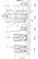
- FIGS. 1 to 5 show the welding of a stud to a plate and the removal of a welding bead which arises in the process in accordance with a preferred embodiment of the present method, FIG. 4 showing an advantageous device for removing the welding bead;
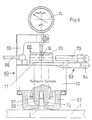
- Figure 6 shows an advantageous device for checking and possibly stretching the welded bolt.
- the welding gun 5 and the workpiece 1 are with a welding power source, not shown, for. B. a conventional welding transformer.
- the part to be welded should generally be at least 1 mm thicker than that of the bolt.
- the bolt is placed with its conically tapering end to be welded onto the workpiece 1, as shown in FIG. 1, and then lifted off, an arc L forming between the workpiece 1 and the bolt 3 in the ceramic ring 2 (FIG.
- the milling tool 7 shown has a cylindrical body 8 with a clamping shaft 9.
- the cylindrical body 8 has two slot-shaped recesses 11 which are inclined, for. B. run at an angle of 75 ° to the axis of rotation and each contain a turning tool 12, which preferably has a hard metal cutting edge.
- the cutting edge forms a rounded front edge 13 through which the welding bead 6 is turned or milled.
- the distance between the opposing cutting edges is preferably selected so that the somewhat thicker lower part 3a of the bolt is also peeled off somewhat.
- the milling can protrude somewhat into the base plate 1 so that it receives a small annular depression 15 there.
- the milling tool 7 can be guided and centered by the bolt 3 itself.
- the central recess 15 receiving the bolt in the milling tool can be dimensioned such that it fits onto the bolt with little play. Inserts of different inner diameters can be provided for the recess 10 for bolts of different diameters (not shown).
- the turning tools are radially adjustable in the slots and can be fixed by means of set screws 14.
- the strength of the butt welded bolts is achieved according to a further development of the invention by a subsequent tensile test or cold stretching.
- the tensile testing and stretching device 60 shown in FIG. 6 can be used for this purpose.
- the device 60 includes a hydraulic cylinder 61 which, for. B. is designed for a pressure of 1,000 bar.
- a support pot 62 is screwed, at the top a fork 63 with a handle 64.
- a dial gauge holder 65 is also releasably attached via a clamping toggle 66.
- the hydraulic cylinder 61 contains a piston 67 with an axial bore, into which a draw bolt 68 is inserted.
- the tension pin 68 has a shaft 69 which extends through the bore of the piston 67 and a head 70 of enlarged diameter which rests on the upper end of the piston 67 via an interposed disk 71.
Landscapes
- Engineering & Computer Science (AREA)
- Mechanical Engineering (AREA)
- Chemical & Material Sciences (AREA)
- Physics & Mathematics (AREA)
- Plasma & Fusion (AREA)
- Crystallography & Structural Chemistry (AREA)
- Materials Engineering (AREA)
- Metallurgy (AREA)
- Organic Chemistry (AREA)
- Investigating Strength Of Materials By Application Of Mechanical Stress (AREA)
- Pressure Welding/Diffusion-Bonding (AREA)
Claims (3)
Applications Claiming Priority (2)
| Application Number | Priority Date | Filing Date | Title |
|---|---|---|---|
| DE19813131055 DE3131055C2 (de) | 1981-08-05 | 1981-08-05 | Verfahren und Vorrichtung zum Bolzenschweißen |
| DE3131055 | 1981-08-05 |
Publications (2)
| Publication Number | Publication Date |
|---|---|
| EP0072941A1 EP0072941A1 (fr) | 1983-03-02 |
| EP0072941B1 true EP0072941B1 (fr) | 1986-12-30 |
Family
ID=6138675
Family Applications (1)
| Application Number | Title | Priority Date | Filing Date |
|---|---|---|---|
| EP82107065A Expired EP0072941B1 (fr) | 1981-08-05 | 1982-08-04 | Méthode et dispositif à soudage de goujons |
Country Status (2)
| Country | Link |
|---|---|
| EP (1) | EP0072941B1 (fr) |
| DE (1) | DE3131055C2 (fr) |
Families Citing this family (8)
| Publication number | Priority date | Publication date | Assignee | Title |
|---|---|---|---|---|
| DE3404643A1 (de) * | 1984-02-09 | 1985-08-14 | Max-Planck-Gesellschaft zur Förderung der Wissenschaften e.V., 3400 Göttingen | Werkzeug zum abdrehen eines zylindrischen werkstuecks |
| DE4322409C2 (de) * | 1993-07-06 | 2003-12-04 | Beck August Gmbh Co | Vorrichtung zur zerspanenden Bearbeitung |
| DE19542394A1 (de) * | 1995-11-14 | 1997-05-15 | Trw Nelson Bolzenschweisstechn | Verfahren und Vorrichtung zum Zuführen von Bolzen und Keramikringen zu einem Bolzenschweißkopf sowie Bolzenschweißkopf zur Durchführung des Verfahrens |
| DE29716234U1 (de) * | 1997-09-09 | 1997-10-23 | Bolzenschweißtechnik Heinz Soyer GmbH, 82237 Wörthsee | Mechanische Prüfvorrichtung zum Feststellen der Qualität einer Schweißung eines auf Blechmaterial geschweißten Bolzens |
| DE19930444C5 (de) * | 1999-07-02 | 2005-10-20 | Daimler Chrysler Ag | Stabilisatoranordnung für ein Kraftfahrzeug |
| DE10004720C1 (de) * | 2000-02-03 | 2001-08-16 | Bayerische Motoren Werke Ag | Vorrichtung und Verfahren zum Prüfen der Befestigungsstelle eines ein Außengewinde aufweisenden Bolzens auf Torsionsfestigkeit |
| DE10153675C1 (de) * | 2001-10-31 | 2003-03-20 | Koester & Co Gmbh | Stützeinrichtung für einen Schweißbolzen |
| DE102015208155B4 (de) * | 2015-05-04 | 2017-11-16 | Bayerische Motoren Werke Aktiengesellschaft | Prüfvorrichtung und Verfahren zur Prüfung von Schweißverbindungen |
Citations (4)
| Publication number | Priority date | Publication date | Assignee | Title |
|---|---|---|---|---|
| DE14379C (de) * | J. B. SAVAGE in Southington (Connecticut, Amerika) | Vorrichtung zum Nachdrehen der Achsschenkel an Wagenrädern | ||
| DE200547C (fr) * | ||||
| US1437831A (en) * | 1921-03-07 | 1922-12-05 | Clarence H Beasecker | Machine for refacing valves |
| DE1864203U (de) * | 1962-09-25 | 1962-12-20 | Ernst Heinkel Flugzeugbau G M | Werkzeug zur entfernung von schweissraupen an rohren. |
Family Cites Families (7)
| Publication number | Priority date | Publication date | Assignee | Title |
|---|---|---|---|---|
| DE524949C (de) * | 1931-05-16 | Otto Reimers | Fraeserkopf mit durch Plangewinde in radialer Richtung einstellbaren Messern | |
| DE468044C (de) * | 1926-09-22 | 1928-11-05 | Metallbank & Metallurg Ges Ag | Verfahren zur Erhoehung der mechanischen Eigenschaften kalt bearbeiteter Metalle |
| GB837411A (en) * | 1955-06-03 | 1960-06-15 | Evan Melfyn Lewis | Improvements in methods of welding studs or like members to plates or other bases |
| DE1853996U (de) * | 1957-06-04 | 1962-06-20 | Siemens Ag | Einrichtung zum vorspannen von maschinenteilen. |
| US3182173A (en) * | 1962-05-21 | 1965-05-04 | Dash Edward | Welding stud and ferrule construction for arc welding |
| DE2108480A1 (en) * | 1971-02-23 | 1972-09-07 | Siemens Ag | Shear pads - to tear off and remove excess welding material after wire butt welding |
| DE2643045A1 (de) * | 1976-09-24 | 1978-03-30 | Soyer Bolzenschweisstechnik | Schweissbolzen oder -stifte |
-
1981
- 1981-08-05 DE DE19813131055 patent/DE3131055C2/de not_active Expired
-
1982
- 1982-08-04 EP EP82107065A patent/EP0072941B1/fr not_active Expired
Patent Citations (4)
| Publication number | Priority date | Publication date | Assignee | Title |
|---|---|---|---|---|
| DE14379C (de) * | J. B. SAVAGE in Southington (Connecticut, Amerika) | Vorrichtung zum Nachdrehen der Achsschenkel an Wagenrädern | ||
| DE200547C (fr) * | ||||
| US1437831A (en) * | 1921-03-07 | 1922-12-05 | Clarence H Beasecker | Machine for refacing valves |
| DE1864203U (de) * | 1962-09-25 | 1962-12-20 | Ernst Heinkel Flugzeugbau G M | Werkzeug zur entfernung von schweissraupen an rohren. |
Also Published As
| Publication number | Publication date |
|---|---|
| DE3131055A1 (de) | 1983-03-03 |
| EP0072941A1 (fr) | 1983-03-02 |
| DE3131055C2 (de) | 1983-05-26 |
Similar Documents
| Publication | Publication Date | Title |
|---|---|---|
| DE2736412A1 (de) | Spannvorrichtung | |
| DE2240613B2 (de) | Drehbare, axial-druckaufnehmende Spannvorrichtung für eine Rundschweißmaschine zur Herstellung von Stabelementen mit kegelförmigen Endstücken unterschiedlicher Größe | |
| EP0259517B1 (fr) | Broche pour le coulant d'une machine-outil, munie d'un seul évidement pour le montage d'un outil de tournage ou de fraisage | |
| EP0312819A1 (fr) | Procédé pour usiner des trous de fixation et de valves dans un disque ou une jante de roue d'un véhicule | |
| EP0072941B1 (fr) | Méthode et dispositif à soudage de goujons | |
| DE102010061546B4 (de) | Vorrichtung und Verfahren zum Lösen von Elektrodenkappen | |
| EP0382877A2 (fr) | Dispositif pour dégauchir et réduire l'épaisseur de pièces de bois d'une taille quelconque, en particulier des pièces minces et courtes | |
| DE1291971B (de) | Verfahren und Werkzeug zum Trennen von zwei durch Punktschweissung verbundenen Metallteilen | |
| CH641385A5 (de) | Langdrehautomat. | |
| DE2336809C3 (de) | Maschine zum Uchtbogen-Schmelzschweissen von Rohr-Stumpf stoßen in horizontaler Schweißnaht-Ebene | |
| EP0309490B1 (fr) | Procede ameliore de reparation de jante sur des roues de voiture dont les percages sont deformes | |
| DE2234825A1 (de) | Verfahren und werkzeug zur herstellung von bohrungen | |
| DE3216929C2 (de) | Fräs=Vorrichtung zum Entgraten von Werkstücken | |
| DE2658344A1 (de) | Vorrichtung zur entgratung zylindrischer roehren | |
| DE2525103A1 (de) | Hohlspindelanschlag | |
| EP0123918B1 (fr) | Mandrin de fraisage et de serrage | |
| DE1752636A1 (de) | Vorrichtung zum Halten der Klemmbacken bei Drehbaenken od.dgl. | |
| DE3340320C2 (de) | Modular-Spannzeug und Verfahren zum Einspannen eines Werkzeuges | |
| DE2503830A1 (de) | Fraeswerkzeug, insbesondere zum bearbeiten von kanten von werkstuecken | |
| DE19836348C2 (de) | Werkzeugaufnahme für eine CNC-gesteuerte Hartdrehmaschine | |
| EP0149994B1 (fr) | Outil à écrouter des boulons standards | |
| DE3432939C2 (fr) | ||
| DE3910693A1 (de) | Vorrichtung zum aufnehmen eines drehstahles in dem revolverkopf einer drehmaschine | |
| DE576759C (de) | Einschleif- und Bohrvorrichtung fuer Ventile und Zylinder | |
| DE3112316A1 (de) | "verfahren zum aussenken von bohrungen in einer platte aus glas- oder kohlenstoffaserverstaerktem material" |
Legal Events
| Date | Code | Title | Description |
|---|---|---|---|
| PUAI | Public reference made under article 153(3) epc to a published international application that has entered the european phase |
Free format text: ORIGINAL CODE: 0009012 |
|
| AK | Designated contracting states |
Designated state(s): FR GB IT |
|
| 17P | Request for examination filed |
Effective date: 19830208 |
|
| ITF | It: translation for a ep patent filed | ||
| GRAA | (expected) grant |
Free format text: ORIGINAL CODE: 0009210 |
|
| AK | Designated contracting states |
Kind code of ref document: B1 Designated state(s): FR GB IT |
|
| ET | Fr: translation filed | ||
| PLBE | No opposition filed within time limit |
Free format text: ORIGINAL CODE: 0009261 |
|
| STAA | Information on the status of an ep patent application or granted ep patent |
Free format text: STATUS: NO OPPOSITION FILED WITHIN TIME LIMIT |
|
| 26N | No opposition filed | ||
| ITTA | It: last paid annual fee | ||
| PG25 | Lapsed in a contracting state [announced via postgrant information from national office to epo] |
Ref country code: GB Effective date: 19890804 |
|
| GBPC | Gb: european patent ceased through non-payment of renewal fee | ||
| PG25 | Lapsed in a contracting state [announced via postgrant information from national office to epo] |
Ref country code: FR Effective date: 19900427 |
|
| REG | Reference to a national code |
Ref country code: FR Ref legal event code: ST |