EP0073013A1 - Interrupteur électrique d'installation - Google Patents
Interrupteur électrique d'installation Download PDFInfo
- Publication number
- EP0073013A1 EP0073013A1 EP82107526A EP82107526A EP0073013A1 EP 0073013 A1 EP0073013 A1 EP 0073013A1 EP 82107526 A EP82107526 A EP 82107526A EP 82107526 A EP82107526 A EP 82107526A EP 0073013 A1 EP0073013 A1 EP 0073013A1
- Authority
- EP
- European Patent Office
- Prior art keywords
- contact
- contact rocker
- fingers
- rocker
- outer fingers
- Prior art date
- Legal status (The legal status is an assumption and is not a legal conclusion. Google has not performed a legal analysis and makes no representation as to the accuracy of the status listed.)
- Granted
Links
- 238000009434 installation Methods 0.000 title 1
- 238000010616 electrical installation Methods 0.000 claims description 6
- 238000013459 approach Methods 0.000 claims description 3
- 238000003780 insertion Methods 0.000 description 1
- 230000037431 insertion Effects 0.000 description 1
- 239000011810 insulating material Substances 0.000 description 1
- 239000007787 solid Substances 0.000 description 1
Images
Classifications
-
- H—ELECTRICITY
- H01—ELECTRIC ELEMENTS
- H01H—ELECTRIC SWITCHES; RELAYS; SELECTORS; EMERGENCY PROTECTIVE DEVICES
- H01H13/00—Switches having rectilinearly-movable operating part or parts adapted for pushing or pulling in one direction only, e.g. push-button switch
- H01H13/50—Switches having rectilinearly-movable operating part or parts adapted for pushing or pulling in one direction only, e.g. push-button switch having a single operating member
- H01H13/56—Switches having rectilinearly-movable operating part or parts adapted for pushing or pulling in one direction only, e.g. push-button switch having a single operating member the contact returning to its original state upon the next application of operating force
- H01H13/60—Switches having rectilinearly-movable operating part or parts adapted for pushing or pulling in one direction only, e.g. push-button switch having a single operating member the contact returning to its original state upon the next application of operating force with contact-driving member moved alternately in opposite directions
Definitions
- a device of this type has become known from DE-OS 19 25 813.
- cut-off approaches are bent out on the side edges of the contact rocker, while for the clamping holder of the middle finger, the contact rocker contains a window-like opening from which a tab bent at an angle to the pushbutton of the switch is bent , behind the front edge of which an extension angled to the middle finger is mounted in a cutting shape.
- the switching plungers designed in this way are extremely difficult to mount in their bearings on the contact rocker. So it is first necessary to pivot the switching plunger at an angle considerably smaller than 90 o to the longitudinal bar of the contact rocker for the insertion of the angled tongue of the middle finger into the window-like opening.
- the angled tongue of the middle finger in the window-like opening and support of the front edge of the outer fingers on the contact rocker can then only be pivoted into the position of use, about 90 o to the longitudinal axis of the contact rocker. Due to the fact that the switching plungers must be pivotable in relation to one another for the mounting, mounting of the second switching plunger is made almost impossible by the first switching plunger already used. For such an assembly, the shift plunger that was used first would have to be pressed in the opposite direction, as a result of which the three fingers can easily be deformed and a reliable mounting of this shift plunger is no longer guaranteed as a result of its spring elasticity being overstretched.
- the object of the invention is to improve the mounting of the switching plunger on the contact rocker such that the switching plunger can be mounted on the contact rocker perpendicular to the contact rocker, according to its position of use. It should be made possible that the switching plunger can be attached to the contact rocker by mechanical assembly. A reliable mounting of the switching plunger on the contact rocker should be guaranteed, which fully meets the requirements for use.
- this is achieved in that the free ends of the fingers have extensions which are curved in opposite directions in a roof shape in such a way that the apex of the extension of the middle finger engages under the edge of the window-like opening and that the apex of the extension of the outer fingers on the side against the Swivel bearing directed bends under tension.
- the contact rockers are formed on the long sides of the bends, which form the pivot bearing with central incisions on the fixed contact part and on the long sides of which the outer fingers of the switching plunger rest.
- the contact rocker has a central, channel-shaped bend directed against the pushbutton, with walls perpendicular to the longitudinal bar of the contact rocker, against which the outer fingers rest.
- a special feature is that a two-point support of the outer fingers is formed by the contact of the outer fingers on the vertical wall of the channel-shaped bend and their extension vertex on the long sides of the side bends, which is in contact with the middle finger lying approximately on their perpendiculars window-like opening form a three-point support for the switching plunger.
- a tension spring is provided as the bistable layers of the contact rocker effecting spring member, the mounting of which on the contact rocker is between the switching plungers and parallel to it, directed against the push button, which is removed from the contact rocker when a window-like opening is formed.
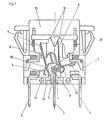
- the switch consists of the housing 1 made of insulating material, to which fixed contact parts 2 and 3 are attached.
- the fixed contact part 2 carries a contact rocker 4 on a pivot bearing, which is pivotably mounted on the latter by means of a tension spring 5.
- the contact rocker 4 has formed on its long sides bends 6, which form the pivot bearing with central cuts 7 in connection with the fixed contact part 2.
- the tension spring 5 the contact rocker 4 is held in its bistable positions for contacting the respective fixed contact parts 3.
- the contact rocker 4 is provided with switching plungers 9 which are pivotally arranged on it at a symmetrical distance from the pivot bearing.
- the switching plunger 9 are in their rest position approximately perpendicular to the longitudinal bar of the contact rocker 4 and can be actuated at their free ends by a push button 15 by means of a switching link 16.
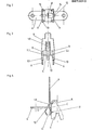
- the switching plungers 9 are designed with three fingers and are supported on the surface of the contact rocker 4 by an end edge 11.1 of the outer fingers 11.
- the contact rocker 4 has a central channel-shaped bend 17 directed against the pushbutton 15 with walls 18 lying at right angles to the longitudinal bar of the contact rocker 4, against which the outer fingers 11 of the switching plunger 9 rest from the outside.
- These outer fingers 11 still have Extensions 13 which extend beyond the end edge 11.1 and which are bent in a roof-shaped manner with their apex against the angles 6.
- the middle finger 10 of the switching plunger 9 passes through a window-like opening 14 of the contact rocker 4 with an extension 12 and is also roof-shaped, but curved in the opposite direction to the roof shape of the extensions 13 of the outer fingers 11.
- the apex of the extension 12 of the middle finger 10 engages behind the edge of the window-like opening 14.
- the extensions 12 and 13 of the switching plunger 9 are held under prestress on the contact rocker 4.
- the front edge 11.1 of the outer fingers 13 forms a pivot bearing in its insert in the angle formed by the longitudinal bar of the contact rocker 4 and the wall 18 of the channel-shaped bend 17.
- a two-point support AB for these outer fingers 11 is formed by the contact of the outer fingers 11 on the vertical wall 18 of the channel-shaped bend 17 and the apex of its extension 13 on the long sides of the lateral bends 6.
- the system D of the extension 12 of the middle finger 10 is located in the window-like opening 14 of the contact rocker 4 approximately on the perpendicular C of the points AB. This results in a solid three-point contact of the switching plunger 9 on the contact rocker 4, so that after each switching operation the switching plunger swings out 9 can always be automatically returned to the vertical starting position on the contact rocker 4.
- a shoulder 8 is provided between the switching plungers 9 and parallel to the latter, directed towards the pushbutton 15, which is removed from the contact rocker 4 when a window-like opening 14 is formed.
Landscapes
- Tumbler Switches (AREA)
Priority Applications (1)
| Application Number | Priority Date | Filing Date | Title |
|---|---|---|---|
| AT82107526T ATE12324T1 (de) | 1981-08-22 | 1982-08-18 | Elektrischer installationsschalter. |
Applications Claiming Priority (2)
| Application Number | Priority Date | Filing Date | Title |
|---|---|---|---|
| DE3133338 | 1981-08-22 | ||
| DE19813133338 DE3133338A1 (de) | 1981-08-22 | 1981-08-22 | Elektrischer installationsschalter |
Publications (2)
| Publication Number | Publication Date |
|---|---|
| EP0073013A1 true EP0073013A1 (fr) | 1983-03-02 |
| EP0073013B1 EP0073013B1 (fr) | 1985-03-20 |
Family
ID=6139935
Family Applications (1)
| Application Number | Title | Priority Date | Filing Date |
|---|---|---|---|
| EP82107526A Expired EP0073013B1 (fr) | 1981-08-22 | 1982-08-18 | Interrupteur électrique d'installation |
Country Status (3)
| Country | Link |
|---|---|
| EP (1) | EP0073013B1 (fr) |
| AT (1) | ATE12324T1 (fr) |
| DE (1) | DE3133338A1 (fr) |
Cited By (2)
| Publication number | Priority date | Publication date | Assignee | Title |
|---|---|---|---|---|
| EP0307364A3 (en) * | 1987-09-09 | 1990-09-05 | Cesare Gallone | Mechanically operated switch |
| EP2398029A1 (fr) | 2010-06-18 | 2011-12-21 | AB Plast S.r.l. | Interrupteur à commande monostable et à contact bistable |
Families Citing this family (3)
| Publication number | Priority date | Publication date | Assignee | Title |
|---|---|---|---|---|
| DE3609851A1 (de) * | 1986-03-22 | 1987-09-24 | Bbc Brown Boveri & Cie | Uebertotpunktschaltsystem |
| DE4312307A1 (de) * | 1993-04-15 | 1994-10-20 | Abb Patent Gmbh | Elektrischer Tastschalter |
| DE4413387C2 (de) * | 1994-04-18 | 1996-11-07 | Abb Patent Gmbh | Elektrischer Tastschalter |
Citations (5)
| Publication number | Priority date | Publication date | Assignee | Title |
|---|---|---|---|---|
| FR1141997A (fr) * | 1956-01-06 | 1957-09-12 | Perfectionnement aux interrupteurs, commutateurs... du type à bascule | |
| DE1104585B (de) * | 1956-01-18 | 1961-04-13 | Rolf Scheunert Dr Ing | Einknopf-Drucktaster zum abwechselnden OEffnen und Schliessen elektrischer Stromkreise |
| DE1931552A1 (de) * | 1968-06-21 | 1970-01-02 | Feller Ag Adolf | Elektrischer Schalter mit einem unter dem Einfluss einer Rueckfuehrfeder stehenden Druckknopf zur Schalterbetaetigung |
| CH491486A (fr) * | 1968-05-30 | 1970-05-31 | Legrand Sa | Contacteur électrique pour installations domestiques |
| DE2533307A1 (de) * | 1975-07-25 | 1977-02-17 | Bbc Brown Boveri & Cie | Elektrischer drucktastenschlater |
Family Cites Families (3)
| Publication number | Priority date | Publication date | Assignee | Title |
|---|---|---|---|---|
| FR1580318A (fr) * | 1968-05-30 | 1969-09-05 | ||
| DE2409604B2 (de) * | 1974-02-26 | 1978-04-27 | Rudolf Schadow Gmbh, 1000 Berlin | Schiebetasten-Schnappschalter |
| AR209530A1 (es) * | 1976-11-25 | 1977-04-29 | Sailly M | Un interruptor-contactor electrico unipolar manual |
-
1981
- 1981-08-22 DE DE19813133338 patent/DE3133338A1/de not_active Withdrawn
-
1982
- 1982-08-18 EP EP82107526A patent/EP0073013B1/fr not_active Expired
- 1982-08-18 AT AT82107526T patent/ATE12324T1/de not_active IP Right Cessation
Patent Citations (5)
| Publication number | Priority date | Publication date | Assignee | Title |
|---|---|---|---|---|
| FR1141997A (fr) * | 1956-01-06 | 1957-09-12 | Perfectionnement aux interrupteurs, commutateurs... du type à bascule | |
| DE1104585B (de) * | 1956-01-18 | 1961-04-13 | Rolf Scheunert Dr Ing | Einknopf-Drucktaster zum abwechselnden OEffnen und Schliessen elektrischer Stromkreise |
| CH491486A (fr) * | 1968-05-30 | 1970-05-31 | Legrand Sa | Contacteur électrique pour installations domestiques |
| DE1931552A1 (de) * | 1968-06-21 | 1970-01-02 | Feller Ag Adolf | Elektrischer Schalter mit einem unter dem Einfluss einer Rueckfuehrfeder stehenden Druckknopf zur Schalterbetaetigung |
| DE2533307A1 (de) * | 1975-07-25 | 1977-02-17 | Bbc Brown Boveri & Cie | Elektrischer drucktastenschlater |
Cited By (2)
| Publication number | Priority date | Publication date | Assignee | Title |
|---|---|---|---|---|
| EP0307364A3 (en) * | 1987-09-09 | 1990-09-05 | Cesare Gallone | Mechanically operated switch |
| EP2398029A1 (fr) | 2010-06-18 | 2011-12-21 | AB Plast S.r.l. | Interrupteur à commande monostable et à contact bistable |
Also Published As
| Publication number | Publication date |
|---|---|
| ATE12324T1 (de) | 1985-04-15 |
| DE3133338A1 (de) | 1983-03-10 |
| EP0073013B1 (fr) | 1985-03-20 |
Similar Documents
| Publication | Publication Date | Title |
|---|---|---|
| EP0218133B1 (fr) | Borne électrique sans vis | |
| DE1765441A1 (de) | Anschlussvorrichtung fuer gedruckte Schaltungen | |
| DE1172757B (de) | Elektrischer Tuerschalter | |
| DE4327502C2 (de) | Schiebeschalter | |
| DE4010121C2 (fr) | ||
| EP0073013B1 (fr) | Interrupteur électrique d'installation | |
| DE730134C (de) | Schnappvorrichtung fuer Schalter, Ventile o. dgl. | |
| DE2904899C2 (de) | Elektrischer Schalter | |
| DE2939583C2 (de) | Drucktastenschalter mit beweglichem, durch eine Rückstellfeder belastetem Schieber | |
| DE2701504C2 (de) | Elektrischer Schalter | |
| DE2705756A1 (de) | Druckknopfschalter fuer elektronische tischrechner o.dgl. | |
| DE2937925C3 (de) | Schalter | |
| DE2547278C2 (de) | Elektrischer Schnappschalter | |
| DE3877262T2 (de) | Testeinheit fuer elektrischen differentialschutzapparat und apparate mit dieser einheit. | |
| DE19619700A1 (de) | Schalter zur Verwendung in elektronischen Vorrichtungen | |
| DE2454388A1 (de) | Elektrischer schalter mit beweglichen federkontakten, die mit stationaeren kontakten schleifend zusammenwirken | |
| DE2904646C2 (de) | Drucktastenschalter | |
| EP0076450B1 (fr) | Interrupteur électrique à bouton-poussoir | |
| DE2801336A1 (de) | Elektrischer kippschalter | |
| DE2951582A1 (de) | Elektrischer schalter | |
| DE3325531A1 (de) | Kontakteinrichtung fuer einen elektrischen schalter | |
| DE3208990C2 (fr) | ||
| DE2804794C2 (de) | Elektrischer Schalter | |
| DE2416340A1 (de) | Elektrische schaltvorri3htung | |
| DE1907855A1 (de) | Elektrischer Schalter |
Legal Events
| Date | Code | Title | Description |
|---|---|---|---|
| PUAI | Public reference made under article 153(3) epc to a published international application that has entered the european phase |
Free format text: ORIGINAL CODE: 0009012 |
|
| AK | Designated contracting states |
Designated state(s): AT CH FR GB IT LI SE |
|
| 17P | Request for examination filed |
Effective date: 19830803 |
|
| ITF | It: translation for a ep patent filed | ||
| GRAA | (expected) grant |
Free format text: ORIGINAL CODE: 0009210 |
|
| AK | Designated contracting states |
Designated state(s): AT CH FR GB IT LI SE |
|
| REF | Corresponds to: |
Ref document number: 12324 Country of ref document: AT Date of ref document: 19850415 Kind code of ref document: T |
|
| ET | Fr: translation filed | ||
| PLBE | No opposition filed within time limit |
Free format text: ORIGINAL CODE: 0009261 |
|
| STAA | Information on the status of an ep patent application or granted ep patent |
Free format text: STATUS: NO OPPOSITION FILED WITHIN TIME LIMIT |
|
| 26N | No opposition filed | ||
| PGFP | Annual fee paid to national office [announced via postgrant information from national office to epo] |
Ref country code: AT Payment date: 19860704 Year of fee payment: 5 |
|
| PG25 | Lapsed in a contracting state [announced via postgrant information from national office to epo] |
Ref country code: GB Effective date: 19890818 Ref country code: AT Effective date: 19890818 |
|
| PG25 | Lapsed in a contracting state [announced via postgrant information from national office to epo] |
Ref country code: SE Effective date: 19890819 |
|
| PG25 | Lapsed in a contracting state [announced via postgrant information from national office to epo] |
Ref country code: LI Effective date: 19890831 Ref country code: CH Effective date: 19890831 |
|
| GBPC | Gb: european patent ceased through non-payment of renewal fee | ||
| PG25 | Lapsed in a contracting state [announced via postgrant information from national office to epo] |
Ref country code: FR Effective date: 19900427 |
|
| REG | Reference to a national code |
Ref country code: CH Ref legal event code: PL |
|
| REG | Reference to a national code |
Ref country code: FR Ref legal event code: ST |
|
| EUG | Se: european patent has lapsed |
Ref document number: 82107526.4 Effective date: 19900418 |