EP0073023A2 - Dispositif de connexion pour câble comprenant des fibres optiques et des conducteurs métalliques - Google Patents
Dispositif de connexion pour câble comprenant des fibres optiques et des conducteurs métalliques Download PDFInfo
- Publication number
- EP0073023A2 EP0073023A2 EP82107581A EP82107581A EP0073023A2 EP 0073023 A2 EP0073023 A2 EP 0073023A2 EP 82107581 A EP82107581 A EP 82107581A EP 82107581 A EP82107581 A EP 82107581A EP 0073023 A2 EP0073023 A2 EP 0073023A2
- Authority
- EP
- European Patent Office
- Prior art keywords
- cable
- connector
- optical fibers
- base
- relative rotation
- Prior art date
- Legal status (The legal status is an assumption and is not a legal conclusion. Google has not performed a legal analysis and makes no representation as to the accuracy of the status listed.)
- Granted
Links
- 239000004020 conductor Substances 0.000 title claims abstract description 10
- 230000003287 optical effect Effects 0.000 title description 2
- 239000013307 optical fiber Substances 0.000 claims abstract description 16
- 238000009825 accumulation Methods 0.000 claims description 3
- 239000007788 liquid Substances 0.000 claims description 3
- 208000031968 Cadaver Diseases 0.000 description 4
- 101000793686 Homo sapiens Azurocidin Proteins 0.000 description 2
- 239000011324 bead Substances 0.000 description 2
- 238000007789 sealing Methods 0.000 description 2
- 239000004264 Petrolatum Substances 0.000 description 1
- 229920002367 Polyisobutene Polymers 0.000 description 1
- 230000008878 coupling Effects 0.000 description 1
- 238000010168 coupling process Methods 0.000 description 1
- 238000005859 coupling reaction Methods 0.000 description 1
- 239000000835 fiber Substances 0.000 description 1
- 210000004907 gland Anatomy 0.000 description 1
- 239000011521 glass Substances 0.000 description 1
- 238000009413 insulation Methods 0.000 description 1
- 239000012212 insulator Substances 0.000 description 1
- 230000000149 penetrating effect Effects 0.000 description 1
- 229940066842 petrolatum Drugs 0.000 description 1
- 235000019271 petrolatum Nutrition 0.000 description 1
- 229920001083 polybutene Polymers 0.000 description 1
- XLYOFNOQVPJJNP-UHFFFAOYSA-N water Substances O XLYOFNOQVPJJNP-UHFFFAOYSA-N 0.000 description 1
Images
Classifications
-
- G—PHYSICS
- G02—OPTICS
- G02B—OPTICAL ELEMENTS, SYSTEMS OR APPARATUS
- G02B6/00—Light guides; Structural details of arrangements comprising light guides and other optical elements, e.g. couplings
- G02B6/44—Mechanical structures for providing tensile strength and external protection for fibres, e.g. optical transmission cables
- G02B6/4439—Auxiliary devices
- G02B6/444—Systems or boxes with surplus lengths
-
- G—PHYSICS
- G02—OPTICS
- G02B—OPTICAL ELEMENTS, SYSTEMS OR APPARATUS
- G02B6/00—Light guides; Structural details of arrangements comprising light guides and other optical elements, e.g. couplings
- G02B6/24—Coupling light guides
- G02B6/36—Mechanical coupling means
- G02B6/38—Mechanical coupling means having fibre to fibre mating means
- G02B6/3807—Dismountable connectors, i.e. comprising plugs
- G02B6/381—Dismountable connectors, i.e. comprising plugs of the ferrule type, e.g. fibre ends embedded in ferrules, connecting a pair of fibres
- G02B6/3817—Dismountable connectors, i.e. comprising plugs of the ferrule type, e.g. fibre ends embedded in ferrules, connecting a pair of fibres containing optical and electrical conductors
-
- G—PHYSICS
- G02—OPTICS
- G02B—OPTICAL ELEMENTS, SYSTEMS OR APPARATUS
- G02B6/00—Light guides; Structural details of arrangements comprising light guides and other optical elements, e.g. couplings
- G02B6/24—Coupling light guides
- G02B6/36—Mechanical coupling means
- G02B6/38—Mechanical coupling means having fibre to fibre mating means
- G02B6/3807—Dismountable connectors, i.e. comprising plugs
- G02B6/381—Dismountable connectors, i.e. comprising plugs of the ferrule type, e.g. fibre ends embedded in ferrules, connecting a pair of fibres
- G02B6/3823—Dismountable connectors, i.e. comprising plugs of the ferrule type, e.g. fibre ends embedded in ferrules, connecting a pair of fibres containing surplus lengths, internal fibre loops
-
- G—PHYSICS
- G02—OPTICS
- G02B—OPTICAL ELEMENTS, SYSTEMS OR APPARATUS
- G02B6/00—Light guides; Structural details of arrangements comprising light guides and other optical elements, e.g. couplings
- G02B6/24—Coupling light guides
- G02B6/36—Mechanical coupling means
- G02B6/38—Mechanical coupling means having fibre to fibre mating means
- G02B6/3807—Dismountable connectors, i.e. comprising plugs
- G02B6/3873—Connectors using guide surfaces for aligning ferrule ends, e.g. tubes, sleeves, V-grooves, rods, pins, balls
- G02B6/3882—Connectors using guide surfaces for aligning ferrule ends, e.g. tubes, sleeves, V-grooves, rods, pins, balls using rods, pins or balls to align a pair of ferrule ends
-
- G—PHYSICS
- G02—OPTICS
- G02B—OPTICAL ELEMENTS, SYSTEMS OR APPARATUS
- G02B6/00—Light guides; Structural details of arrangements comprising light guides and other optical elements, e.g. couplings
- G02B6/24—Coupling light guides
- G02B6/36—Mechanical coupling means
- G02B6/38—Mechanical coupling means having fibre to fibre mating means
- G02B6/3807—Dismountable connectors, i.e. comprising plugs
- G02B6/3887—Anchoring optical cables to connector housings, e.g. strain relief features
-
- G—PHYSICS
- G02—OPTICS
- G02B—OPTICAL ELEMENTS, SYSTEMS OR APPARATUS
- G02B6/00—Light guides; Structural details of arrangements comprising light guides and other optical elements, e.g. couplings
- G02B6/44—Mechanical structures for providing tensile strength and external protection for fibres, e.g. optical transmission cables
- G02B6/4439—Auxiliary devices
- G02B6/444—Systems or boxes with surplus lengths
- G02B6/4441—Boxes
- G02B6/4446—Cable boxes, e.g. splicing boxes with two or more multi fibre cables
- G02B6/44465—Seals
-
- H—ELECTRICITY
- H01—ELECTRIC ELEMENTS
- H01R—ELECTRICALLY-CONDUCTIVE CONNECTIONS; STRUCTURAL ASSOCIATIONS OF A PLURALITY OF MUTUALLY-INSULATED ELECTRICAL CONNECTING ELEMENTS; COUPLING DEVICES; CURRENT COLLECTORS
- H01R13/00—Details of coupling devices of the kinds covered by groups H01R12/70 or H01R24/00 - H01R33/00
- H01R13/56—Means for preventing chafing or fracture of flexible leads at outlet from coupling part
- H01R13/565—Torsion-relieving
-
- H—ELECTRICITY
- H01—ELECTRIC ELEMENTS
- H01R—ELECTRICALLY-CONDUCTIVE CONNECTIONS; STRUCTURAL ASSOCIATIONS OF A PLURALITY OF MUTUALLY-INSULATED ELECTRICAL CONNECTING ELEMENTS; COUPLING DEVICES; CURRENT COLLECTORS
- H01R13/00—Details of coupling devices of the kinds covered by groups H01R12/70 or H01R24/00 - H01R33/00
- H01R13/62—Means for facilitating engagement or disengagement of coupling parts or for holding them in engagement
- H01R13/622—Screw-ring or screw-casing
-
- G—PHYSICS
- G02—OPTICS
- G02B—OPTICAL ELEMENTS, SYSTEMS OR APPARATUS
- G02B6/00—Light guides; Structural details of arrangements comprising light guides and other optical elements, e.g. couplings
- G02B6/24—Coupling light guides
- G02B6/36—Mechanical coupling means
- G02B6/38—Mechanical coupling means having fibre to fibre mating means
- G02B6/3807—Dismountable connectors, i.e. comprising plugs
- G02B6/381—Dismountable connectors, i.e. comprising plugs of the ferrule type, e.g. fibre ends embedded in ferrules, connecting a pair of fibres
- G02B6/3826—Dismountable connectors, i.e. comprising plugs of the ferrule type, e.g. fibre ends embedded in ferrules, connecting a pair of fibres characterised by form or shape
- G02B6/3831—Dismountable connectors, i.e. comprising plugs of the ferrule type, e.g. fibre ends embedded in ferrules, connecting a pair of fibres characterised by form or shape comprising a keying element on the plug or adapter, e.g. to forbid wrong connection
-
- G—PHYSICS
- G02—OPTICS
- G02B—OPTICAL ELEMENTS, SYSTEMS OR APPARATUS
- G02B6/00—Light guides; Structural details of arrangements comprising light guides and other optical elements, e.g. couplings
- G02B6/24—Coupling light guides
- G02B6/36—Mechanical coupling means
- G02B6/38—Mechanical coupling means having fibre to fibre mating means
- G02B6/3807—Dismountable connectors, i.e. comprising plugs
- G02B6/3833—Details of mounting fibres in ferrules; Assembly methods; Manufacture
- G02B6/3851—Ferrules having keying or coding means
-
- G—PHYSICS
- G02—OPTICS
- G02B—OPTICAL ELEMENTS, SYSTEMS OR APPARATUS
- G02B6/00—Light guides; Structural details of arrangements comprising light guides and other optical elements, e.g. couplings
- G02B6/24—Coupling light guides
- G02B6/36—Mechanical coupling means
- G02B6/38—Mechanical coupling means having fibre to fibre mating means
- G02B6/3807—Dismountable connectors, i.e. comprising plugs
- G02B6/389—Dismountable connectors, i.e. comprising plugs characterised by the method of fastening connecting plugs and sockets, e.g. screw- or nut-lock, snap-in, bayonet type
- G02B6/3894—Screw-lock type
-
- H—ELECTRICITY
- H01—ELECTRIC ELEMENTS
- H01R—ELECTRICALLY-CONDUCTIVE CONNECTIONS; STRUCTURAL ASSOCIATIONS OF A PLURALITY OF MUTUALLY-INSULATED ELECTRICAL CONNECTING ELEMENTS; COUPLING DEVICES; CURRENT COLLECTORS
- H01R24/00—Two-part coupling devices, or either of their cooperating parts, characterised by their overall structure
- H01R24/86—Parallel contacts arranged about a common axis
Definitions
- connection between a cable comprising both optical fibers and metallic conductors in particular for transmitting electrical energy from the supply of underwater cable repeaters, and either another cable or a cable element connection with a repeater, is relatively new and has not yet received a satisfactory solution. It tends to occur at such connections torsions, resulting from the fact that the cable can not rotate about its axis, and may damage the cable sheath or the casing of the connection device, and allow the introduction of water inside the cable or connection.
- the present invention notably makes it possible to remedy these drawbacks. Its purpose is to provide a device which ensures, with a certain freedom of rotation, between the cables opposite, or between a cable and the connecting cable element with a repeater, a simultaneous connection by a single mechanical assembly.
- connection device is characterized in that the connector and / or the base are connected to a junction body with the end of a cable comprising means allowing a relatively angularly limited relative rotation of the connector and / or of the base relative to the end of the corresponding cable.
- the barrel of the connector itself 1 is disposed in a connector body 2 on which is mounted a coupling nut 3 with thread 4, provided with an internal groove for housing a sealing segment 5
- the connector body is provided on its internal periphery with a groove 5A in which a sealing gasket 5B is arranged.
- the electrical continuity clamp 6 is arranged in an insulator 7, beyond the insulating sleeve 8.
- the cylindrical end piece 9 forms the passage conduit for the optical fiber 10.
- the nut 11 ensures the attachment to the connector body 2 of the outer jacket of the connector, which will appear in FIG. 2.
- the internal cavity 12 intended to accommodate the fiber lengtheners optical and electrical conductors.
- the barrel is provided with a coding pin 13.
- the barrel of the base 20 is surrounded by a base body 21 fixed to the connector housing 22 by bolts 23 and provided with an annular groove for housing a seal 24.
- the continuity pin electric 25 is mounted on the glass bead 26 and the seal 27.
- the cylindrical tip 28 allows the passage of an optical fiber.
- the blind bore 29 forms a keying piece for angular positioning, in connection with the pin 13 already mentioned.
- Figures 2 and 3 show the part of the connection device for controlling its orientation.
- a first ball 30 is disposed in a cavity of the connector body 2.
- a second ball 31 is disposed in a cavity of the outer jacket 32 of the connector, which is free to rotate around the connector body. These balls both protrude into an annular space 33.
- the freedom of rotation of the outer jacket is limited only for the abutment of the ball 31 against the ball 30, either from the left (position 31A ), or from the right (position 31B). The relative freedom of rotation is therefore little less than 36 ° .
- the internal cavity 12 extend the lengths of optical fibers such as 10 and of electrical conductors such as 34 allowing them to adapt to the relative rotations of the connector body relative to the outer jacket secured to the end of the cable.
- the jacket 32 has an annular groove 35 in which the annular bead 36 of an elastomeric cap 37 engages, which surrounds the end of the cable.
- This end of the cable is held inside the jacket 32 by means of a lashing piece 38, provided with a stop ring 39 and a gland seal 40, surrounding the sheath of the cable, this joint being tightened by the nut 41 and the washer 42.
- the volume 37A inside the cap 37 around the nut 41 is filled with a liquid of high viscosity, such as a very viscous petrolatum, polybutene or polyisobutene.
Landscapes
- Physics & Mathematics (AREA)
- General Physics & Mathematics (AREA)
- Optics & Photonics (AREA)
- Connector Housings Or Holding Contact Members (AREA)
- Mechanical Coupling Of Light Guides (AREA)
- Details Of Connecting Devices For Male And Female Coupling (AREA)
- Cable Accessories (AREA)
Abstract
- a) une embase comportant unbarillet à pièces de raccordement électrique mâles (25), un embout contenant les fibres optiques (28) et un organe de positionnement angulaire (29),
- b) un connecteur comportant un barillet à pièces de raccordement électrique femelles (6), un embout contenant les fibres optiques (9) et un organe de positionnement angulaire.
Description
- La présente invention concerne un dispositif de connexion pour câble comprenant à la fois des fibres optiques et des conducteurs métalliques comprenant
- a) une embase comportant un barillet à pièces de raccordement électrique mâles, un embout contenant les fibres optiques et un organe de positionnement angulaire,
- b) un connecteur comportant un barillet à pièces de raccordement électrique femelles, un embout contenant les fibres optiques et un organe de positionnement angulaire.
- Le problème de la connexion entre un câble comprenant à la fois des fibres optiques et des conducteurs métalliques, notamment pour transmission d'énergie électrique de l'alimentation de répéteurs de câbles sous- marins, et soit un autre câble, soit un élément de câble de liaison avec un répéteur, est relativement nouveau et n'a pas encore reçu de solution satisfaisante. Il tend à se produire au niveau de telles connexions des torsions, résultant du fait que le câble ne peut tourner autour de son axe, et susceptibles d'endommager la gaine du câble ou l'enveloppe du dispositif de connexion, et de permettre l'introduction d'eau à l'intérieur du câble ou de la connexion.
- La présente invention permet notamment de remédier à ces inconvénients. Elle a pour but de procurer un dispositif qui assure, avec une certaine liberté de rotation, entre les câbles en vis-à-vis, ou entre un câble et l'élément de câble de liaison avec un répéteur, une connexion simultanée par un seul ensemble mécanique.
- Le dispositif de connexion selon l'invention est caractérisé en ce que le connecteur et/ou l'embase sont reliés à un corps de jonction avec l'extrémité d'un câble comportant des moyens permettant une rotation relative limitée angulairement du connecteur et/ou de l'embase par rapport à l'extrémité du câble correspondant.
- Il répond en outre de préférence à au moins l'une des caractéristiques suivantes :
- - Les moyens permettant une rotation relative sont disposés de façon que ladite rotation soit au maximum voisine de 360°.
- - Les moyens permettant une rotation relative comprennent une bille disposée dans une cavité d'un corps interne et une bille disposée dans une cavité d'une chemise externe susceptible de tourner autour du corps interne, lesdites billes pénétrant l'une et l'autre dans une gorge circonférentielle séparant ledit corps interne et ladite chemise externe.
- - Le corps de jonction comporte une cavité interne permettant l'accumulation d'une surlongueur de fibres optiques et de conducteurs correspondant au minimum à la rotation relative maximale prévue.
- - L'extrémité de la chemise externe la plus proche du câble est reliée à la gaine de celui-ci par une coiffe élastique entourant un volume interne rempli d'un liquide visqueux.
- Il est décrit ci-après,, à titre d'exemple et en référence aux figures du dessin annexé, un dispositif de connexion selon l'invention entre un câble à deux fibres optiques et deux conducteurs électriques et un répéteur.
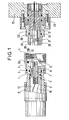
- La figure 1 représente en coupe diamétrale, écartés l'un de l'autre, le barillet du connecteur du câble et le barillet de l'embase du répéteur.
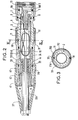
- La figure 2 représente en coupe diamétrale le connecteur du câble, avec son organe permettant la rotation relative du connecteur par rapport à l'extrémité du câble.
- La figure 3 représente une section droite par l'axe III-III de la figure 2 montrant le fonctionnement du système de billes limitant la rotation relative.
- Dans la figure 1, le barillet du connecteur proprement dit 1 est disposé dans un corps de connecteur 2 sur lequel est monté un écrou d'accouplement 3 à filetage 4, muni d'une gorge interne de logement d'un segment d'étanchéité 5. Le corps de connecteur est muni sur son pourtour interne d'une gorge 5A dans laquelle est disposé un joint d'étanchéité 5B. La pince de continuité électrique 6 est disposée dans un isolant 7, au-delà de la douille isolante 8. L'embout cylindrique 9 forme le conduit de passage pour la fibre optique 10. L'écrou 11 assure la fixation au corps de connecteur 2 de la chemise extérieure du connecteur, qui apparaîtra sur la figure 2. A l'arrière de l'isolant 7 se trouve la cavité interne 12, destinée à loger les surlongueurs de fibres optiques et de conducteurs électriques. Le barillet est muni d'un pion de détrompage 13.
- Le barillet de l'embase 20 est entouré d'un corps d'embase 21 fixé sur le boîtier du connecteur 22 par des boulons 23 et muni d'une gorge annulaire de logement d'un joint d'étanchéité 24. La broche de continuité électrique 25 est montée sur la perle de verre 26 et le joint 27. L'embout cylindrique 28 permet le passage d'une fibre optique. L'alésage borgne 29 forme pièce de détrompage pour le positionnement angulaire, en liaison avec le pion 13 déjà mentionné.
- Les figures 2 et 3 représentent la partie du dispositif de connexion permettant le contrôle de son orientation.
- Une première bille 30 est disposée dans une cavité du corps de connecteur 2. Une seconde bille 31 est disposée dans une cavité de la chemise extérieure 32 du connecteur, qui est libre en rotation autour du corps de connecteur. Ces billes font toutes deux saillie dans un espace annulaire 33. On voit que la liberté de rotation de la chemise extérieure n'est limitée que pour l'arrivée en butée de la bille 31 contre la bille 30, soit par la gauche (position 31A), soit par la droite (position 31B). La liberté de rotation relative est donc peu inférieure à 360°.
- Dans la cavité interne 12 s'étendent les surlongueurs de fibres optiques telles que 10 et de conducteurs électriques tel que 34 leur permettant de s'adapter aux rotations relatives du corps de connecteur par rapport à la chemise extérieure solidaire de l'extrémité du câble.
- Dans sa partie arrière, la chemise 32 comporte une gorge annulaire 35, dans laquelle s'engage le bourrelet annulaire 36 d'une coiffe 37 en élastomère, qui vient entourer l'extrémité du câble.
- Cette extrémité du câble est maintenue à l'intérieur de la chemise 32 à l'aide d'une pièce d'arrimage 38, munie d'une bague d'arrêt 39 et d'un joint presse-étoupe 40, entourant la gaine du câble, ce joint étant serré par l'écrou 41 et la rondelle 42. Le volume 37A intérieur à la coiffe 37 autour de l'écrou 41 est rempli d'un liquide de viscosité élevée, tel qu'une vaseline très visqueuse, du polybutène ou du polyiso- butène.
- D'autres joints tels que 43 entre le corps de connecteur et la chemise extérieure, et 44 entre la chemise extérieure et la pièce d'arrimage, permettent de parfaire l'étanchéité du dispositif de connexion.
Claims (5)
Applications Claiming Priority (2)
| Application Number | Priority Date | Filing Date | Title |
|---|---|---|---|
| FR8116292 | 1981-08-26 | ||
| FR8116292A FR2512216A1 (fr) | 1981-08-26 | 1981-08-26 | Dispositif de connexion pour cable comprenant des fibres optiques et des conducteurs metalliques |
Publications (3)
| Publication Number | Publication Date |
|---|---|
| EP0073023A2 true EP0073023A2 (fr) | 1983-03-02 |
| EP0073023A3 EP0073023A3 (en) | 1986-03-26 |
| EP0073023B1 EP0073023B1 (fr) | 1989-12-20 |
Family
ID=9261683
Family Applications (1)
| Application Number | Title | Priority Date | Filing Date |
|---|---|---|---|
| EP82107581A Expired EP0073023B1 (fr) | 1981-08-26 | 1982-08-19 | Dispositif de connexion pour câble comprenant des fibres optiques et des conducteurs métalliques |
Country Status (6)
| Country | Link |
|---|---|
| US (1) | US4568145A (fr) |
| EP (1) | EP0073023B1 (fr) |
| JP (1) | JPS5842020A (fr) |
| CA (1) | CA1217666A (fr) |
| DE (1) | DE3280071D1 (fr) |
| FR (1) | FR2512216A1 (fr) |
Cited By (5)
| Publication number | Priority date | Publication date | Assignee | Title |
|---|---|---|---|---|
| GB2164506A (en) * | 1984-09-12 | 1986-03-19 | Mcgeoch & Co William | Coupling device between relatively rotatable members |
| GB2176907A (en) * | 1985-06-21 | 1987-01-07 | Gen Electric Plc | Optical fibre apparatus |
| FR2707765A1 (fr) * | 1993-07-12 | 1995-01-20 | Jupiter Const Electr | Fiche de connexion optique à verrouillage axial et ensemble de connexion le comprenant. |
| GB2303221A (en) * | 1995-07-10 | 1997-02-12 | Alcatel Kabel Norge As | Sealing two cylindrical surfaces with grooved cylindrical sleeve |
| EP0766348A1 (fr) * | 1995-09-29 | 1997-04-02 | Endress + Hauser GmbH + Co. | Connecteur |
Families Citing this family (50)
| Publication number | Priority date | Publication date | Assignee | Title |
|---|---|---|---|---|
| US4687292A (en) * | 1984-04-18 | 1987-08-18 | Siemens Aktiengesellschaft | Light waveguide plug connector |
| US4962991A (en) * | 1985-01-23 | 1990-10-16 | Raytheon Company | Quick-disconnect waveguide connector assembly |
| US4720630A (en) * | 1985-04-05 | 1988-01-19 | Hitachi, Ltd. | Active optical connector including an electronic circuit board and an optical fiber |
| JPS61189209U (fr) * | 1985-05-16 | 1986-11-26 | ||
| CA1297157C (fr) * | 1987-07-13 | 1992-03-10 | Geoffrey Nelson Bowling | Systeme d'alimentation electrique et de communication programmable a boucle fermee |
| CA1321089C (fr) * | 1988-05-06 | 1993-08-10 | Adc Telecommunications, Inc. | Commutateur optique |
| US5028114A (en) * | 1988-09-29 | 1991-07-02 | Siemens Aktiengesellschaft | Plug connector for fiber optic cables |
| GB9027748D0 (en) * | 1990-12-20 | 1991-02-13 | Baroid Technology Inc | Two-way fibre optic communication system |
| EP0695429A1 (fr) * | 1991-05-09 | 1996-02-07 | Itt Industries, Inc. | Connecteur de fibre optique avec pointes d'aboutement |
| USRE40150E1 (en) | 1994-04-25 | 2008-03-11 | Matsushita Electric Industrial Co., Ltd. | Fiber optic module |
| US6220878B1 (en) | 1995-10-04 | 2001-04-24 | Methode Electronics, Inc. | Optoelectronic module with grounding means |
| US5546281A (en) | 1995-01-13 | 1996-08-13 | Methode Electronics, Inc. | Removable optoelectronic transceiver module with potting box |
| US5717533A (en) | 1995-01-13 | 1998-02-10 | Methode Electronics Inc. | Removable optoelectronic module |
| US6923273B2 (en) | 1997-10-27 | 2005-08-02 | Halliburton Energy Services, Inc. | Well system |
| US7059881B2 (en) * | 1997-10-27 | 2006-06-13 | Halliburton Energy Services, Inc. | Spoolable composite coiled tubing connector |
| US6296066B1 (en) | 1997-10-27 | 2001-10-02 | Halliburton Energy Services, Inc. | Well system |
| US6607044B1 (en) * | 1997-10-27 | 2003-08-19 | Halliburton Energy Services, Inc. | Three dimensional steerable system and method for steering bit to drill borehole |
| DE19810561A1 (de) * | 1998-03-11 | 1999-09-16 | Siemens Ag | Hybrider Datenstecker |
| US6203333B1 (en) | 1998-04-22 | 2001-03-20 | Stratos Lightwave, Inc. | High speed interface converter module |
| US6179627B1 (en) | 1998-04-22 | 2001-01-30 | Stratos Lightwave, Inc. | High speed interface converter module |
| JP4099271B2 (ja) * | 1998-09-14 | 2008-06-11 | 富士通株式会社 | 光コネクタ |
| US7090509B1 (en) | 1999-06-11 | 2006-08-15 | Stratos International, Inc. | Multi-port pluggable transceiver (MPPT) with multiple LC duplex optical receptacles |
| US6220873B1 (en) | 1999-08-10 | 2001-04-24 | Stratos Lightwave, Inc. | Modified contact traces for interface converter |
| US6659200B1 (en) | 1999-12-20 | 2003-12-09 | Halliburton Energy Services, Inc. | Actuator assembly and method for actuating downhole assembly |
| US6454462B2 (en) * | 2000-04-18 | 2002-09-24 | Kings Electronics Co., Inc. | HDTV camera cable connector |
| DE10143058A1 (de) * | 2001-09-03 | 2003-03-20 | Reinhold Blazejewski | Steckverbinder für ein Kombinationskabel |
| US7304241B2 (en) * | 2004-09-17 | 2007-12-04 | Karl-Heinz Trieb | Swivel connector, cable, and assembly |
| US7186033B2 (en) * | 2005-02-23 | 2007-03-06 | Schlumberger Technology Corporation | Fiber optic booster connector |
| US7393144B2 (en) * | 2005-04-15 | 2008-07-01 | Adc Telecommunications, Inc. | Hybrid fiber/copper connector system and method |
| US7490994B2 (en) * | 2006-11-29 | 2009-02-17 | Adc Telecommunications, Inc. | Hybrid fiber/copper connector system and method |
| US7481585B2 (en) | 2006-11-29 | 2009-01-27 | Adc Telecommunications, Inc. | Hybrid fiber/copper connector system and method |
| US7540666B2 (en) * | 2007-02-27 | 2009-06-02 | Corning Cable Systems Llc | Articulated force application for multi-fiber ferrules |
| US8083416B2 (en) * | 2007-11-30 | 2011-12-27 | Adc Telecommunications, Inc. | Hybrid fiber/copper connector system and method |
| EP2354824A1 (fr) * | 2010-01-29 | 2011-08-10 | CCS Technology Inc. | Connecteur hybride |
| CN102906613A (zh) | 2010-03-10 | 2013-01-30 | 康宁光缆系统有限公司 | 允许单/多路接头的光纤尾端组件 |
| US9052468B2 (en) | 2011-03-04 | 2015-06-09 | Corning Cable Systems Llc | Fiber optic adapter mount |
| US9110266B2 (en) | 2011-07-29 | 2015-08-18 | Corning Cable Systems Llc | Fiber optic cables seal and/or strain relief members, and related assemblies and methods |
| US8842962B2 (en) | 2012-01-27 | 2014-09-23 | Corning Cable Systems Llc | Fiber optic cable strain relief device and method |
| CN102593687B (zh) * | 2012-03-13 | 2014-08-13 | 中国电子科技集团公司第八研究所 | 可拔插光电复合连接器的装配工艺 |
| CN102540357B (zh) * | 2012-03-13 | 2014-10-01 | 中国电子科技集团公司第八研究所 | 可拔插光电复合连接器 |
| EP2725396B1 (fr) | 2012-10-26 | 2016-09-14 | CCS Technology, Inc. | Dispositif de réduction de tension et dispositif de distribution à fibres optiques |
| US9436569B2 (en) * | 2013-08-16 | 2016-09-06 | The Boeing Company | Methods and systems for communicatively coupling vehicles and ground systems |
| US10084550B2 (en) | 2013-08-16 | 2018-09-25 | The Boeing Company | Methods and systems for communicatively coupling vehicles and ground systems |
| US9488793B2 (en) | 2013-09-10 | 2016-11-08 | Corning Optical Communications LLC | Combined optical fiber and power cable |
| EP2879242A1 (fr) * | 2013-12-02 | 2015-06-03 | Alcatel- Lucent Shanghai Bell Co., Ltd | Connecteur opto-électrique avec un élément de rotation |
| DE102016103955A1 (de) * | 2016-03-04 | 2017-09-07 | Atlas Elektronik Gmbh | Unterwasserstecker für ein Unterwasserfahrzeug sowie ein Verfahren damit und Unterwasserfahrzeug |
| US10295771B2 (en) | 2016-05-03 | 2019-05-21 | Corning Optical Communications LLC | Telecommunications terminal with removable modules |
| US11323435B2 (en) | 2019-05-08 | 2022-05-03 | The Boeing Company | Method and apparatus for advanced security systems over a power line connection |
| CN112769090B (zh) * | 2021-04-08 | 2021-06-29 | 天津七一二移动通信有限公司 | 一种通信电缆接头结构及其安装方法 |
| US12394935B2 (en) * | 2022-03-31 | 2025-08-19 | Rampart Products Llc | Galvanic corrosion-proof underwater electrical interconnect |
Family Cites Families (8)
| Publication number | Priority date | Publication date | Assignee | Title |
|---|---|---|---|---|
| GB1458897A (en) * | 1974-07-09 | 1976-12-15 | Cannon Electric Great Britain | Connectors |
| US4427879A (en) * | 1975-04-18 | 1984-01-24 | Allied Corporation | Optoelectronic connector assembly |
| US4124272A (en) * | 1976-12-14 | 1978-11-07 | Westinghouse Electric Corp. | Rotary fiber optic waveguide coupling |
| DE2806496A1 (de) * | 1977-02-22 | 1978-08-31 | Itt Ind Gmbh Deutsche | Mehrfach-steckverbinder |
| DE2921814A1 (de) * | 1978-05-31 | 1979-12-06 | Bunker Ramo | Faseroptischer oder elektrischer verbinder |
| JPS5922203B2 (ja) * | 1978-10-06 | 1984-05-25 | ケイディディ株式会社 | 光海底中継器のフイ−ドスル |
| FR2473733A1 (fr) * | 1980-01-11 | 1981-07-17 | Commissariat Energie Atomique | Connecteur pour fibres optiques |
| GB2092396B (en) * | 1981-01-07 | 1985-01-30 | Bunker Ramo | Push pull connector |
-
1981
- 1981-08-26 FR FR8116292A patent/FR2512216A1/fr active Granted
-
1982
- 1982-08-19 DE DE8282107581T patent/DE3280071D1/de not_active Expired - Fee Related
- 1982-08-19 EP EP82107581A patent/EP0073023B1/fr not_active Expired
- 1982-08-25 CA CA000410131A patent/CA1217666A/fr not_active Expired
- 1982-08-25 JP JP57147507A patent/JPS5842020A/ja active Granted
-
1984
- 1984-12-04 US US06/678,362 patent/US4568145A/en not_active Expired - Fee Related
Cited By (9)
| Publication number | Priority date | Publication date | Assignee | Title |
|---|---|---|---|---|
| GB2164506A (en) * | 1984-09-12 | 1986-03-19 | Mcgeoch & Co William | Coupling device between relatively rotatable members |
| GB2176907A (en) * | 1985-06-21 | 1987-01-07 | Gen Electric Plc | Optical fibre apparatus |
| GB2176907B (en) * | 1985-06-21 | 1989-07-12 | Gen Electric Plc | A housing for optical fibre |
| FR2707765A1 (fr) * | 1993-07-12 | 1995-01-20 | Jupiter Const Electr | Fiche de connexion optique à verrouillage axial et ensemble de connexion le comprenant. |
| WO1995002840A1 (fr) * | 1993-07-12 | 1995-01-26 | Framatome Connectors International | Fiche de connexion optique a verrouillage axial et ensemble de connexion le comprenant |
| GB2303221A (en) * | 1995-07-10 | 1997-02-12 | Alcatel Kabel Norge As | Sealing two cylindrical surfaces with grooved cylindrical sleeve |
| GB2303221B (en) * | 1995-07-10 | 1998-11-18 | Alcatel Kabel Norge As | A sealing device for use between two cylindrical surfaces |
| EP0766348A1 (fr) * | 1995-09-29 | 1997-04-02 | Endress + Hauser GmbH + Co. | Connecteur |
| US5795173A (en) * | 1995-09-29 | 1998-08-18 | Endress + Hauser Gmbh + Co. | Plug connector |
Also Published As
| Publication number | Publication date |
|---|---|
| FR2512216B1 (fr) | 1985-04-26 |
| FR2512216A1 (fr) | 1983-03-04 |
| DE3280071D1 (de) | 1990-01-25 |
| US4568145A (en) | 1986-02-04 |
| JPS5842020A (ja) | 1983-03-11 |
| CA1217666A (fr) | 1987-02-10 |
| EP0073023A3 (en) | 1986-03-26 |
| EP0073023B1 (fr) | 1989-12-20 |
| JPH0155442B2 (fr) | 1989-11-24 |
Similar Documents
| Publication | Publication Date | Title |
|---|---|---|
| EP0073023B1 (fr) | Dispositif de connexion pour câble comprenant des fibres optiques et des conducteurs métalliques | |
| EP1249914B1 (fr) | Guide-câble pour boítier étanche et ensemble d'étanchéité comportant un tel guide | |
| FR2566974A1 (fr) | Dispositif d'etancheite pour traversee de cable conducteur | |
| FR2643171A1 (fr) | Systeme detecteur d'obstacle comprenant un ensemble de connexion perfectionne | |
| MXPA03004892A (es) | Conector para cable coaxial para linea telefonica. | |
| CH634693A5 (fr) | Raccord pour cables electriques a chemise de plomb, isoles au papier. | |
| FR2823609A1 (fr) | Joint d'etancheite pour cables | |
| FR2479544A1 (fr) | Cable electrique pourvu d'une gaine protectrice et destine a la commande electro-hydraulique d'elements de soutenement dans des travaux d'extraction miniere | |
| EP0595708B1 (fr) | Dispositif anti-retrait d'isolation, pour câble de puissance à isolation synthétique | |
| FR2557390A1 (fr) | Cable de moyenne tension, isole par du papier, ferme | |
| FR2895578A1 (fr) | Connecteur electrique haute tension immergeable en milieu fluide | |
| FR2645683A1 (fr) | Boite de raccordement pour branchement de cables de derivation sur un cable principal | |
| EP0016340B1 (fr) | Dispositif de raccordement entre les conducteurs extérieurs de deux paires coaxiales | |
| FR2707765A1 (fr) | Fiche de connexion optique à verrouillage axial et ensemble de connexion le comprenant. | |
| FR2578690A1 (fr) | Dispositif de connexion electrique unipolaire entre deux modules assembles mecaniquement bout a bout d'un groupe motopompe immerge | |
| WO1998029052A1 (fr) | Attachement tournant polyvalent | |
| EP0511079A1 (fr) | Connecteur électrique de puissance | |
| EP0051098B1 (fr) | Connecteur pour câble coaxial | |
| FR2681148A1 (fr) | Joint tournant electro-optique. | |
| FR2725080A1 (fr) | Connexion pour plot lumineux | |
| FR2633673A1 (fr) | Pompe ou moteur volumique helicoidal | |
| FR2494051A1 (fr) | Manchon protecteur pour les joints de raccordement et de division des cables electriques et telephoniques | |
| FR2506552A1 (fr) | Embout pour cable bipolaire refroidi par eau | |
| FR2703846A1 (fr) | Adaptateur pour lampe. | |
| EP0961349A1 (fr) | Dispositifs de raccordement étanche d'antennes |
Legal Events
| Date | Code | Title | Description |
|---|---|---|---|
| PUAI | Public reference made under article 153(3) epc to a published international application that has entered the european phase |
Free format text: ORIGINAL CODE: 0009012 |
|
| AK | Designated contracting states |
Designated state(s): CH DE FR GB IT LI NL SE |
|
| PUAL | Search report despatched |
Free format text: ORIGINAL CODE: 0009013 |
|
| AK | Designated contracting states |
Kind code of ref document: A3 Designated state(s): CH DE FR GB IT LI NL SE |
|
| 17P | Request for examination filed |
Effective date: 19860918 |
|
| 17Q | First examination report despatched |
Effective date: 19871203 |
|
| GRAA | (expected) grant |
Free format text: ORIGINAL CODE: 0009210 |
|
| AK | Designated contracting states |
Kind code of ref document: B1 Designated state(s): CH DE FR GB IT LI NL SE |
|
| REF | Corresponds to: |
Ref document number: 3280071 Country of ref document: DE Date of ref document: 19900125 |
|
| GBT | Gb: translation of ep patent filed (gb section 77(6)(a)/1977) | ||
| ITF | It: translation for a ep patent filed | ||
| PLBE | No opposition filed within time limit |
Free format text: ORIGINAL CODE: 0009261 |
|
| STAA | Information on the status of an ep patent application or granted ep patent |
Free format text: STATUS: NO OPPOSITION FILED WITHIN TIME LIMIT |
|
| 26N | No opposition filed | ||
| PGFP | Annual fee paid to national office [announced via postgrant information from national office to epo] |
Ref country code: DE Payment date: 19930519 Year of fee payment: 12 Ref country code: CH Payment date: 19930519 Year of fee payment: 12 |
|
| PGFP | Annual fee paid to national office [announced via postgrant information from national office to epo] |
Ref country code: SE Payment date: 19930521 Year of fee payment: 12 |
|
| PGFP | Annual fee paid to national office [announced via postgrant information from national office to epo] |
Ref country code: GB Payment date: 19930526 Year of fee payment: 12 |
|
| PGFP | Annual fee paid to national office [announced via postgrant information from national office to epo] |
Ref country code: FR Payment date: 19930527 Year of fee payment: 12 |
|
| ITTA | It: last paid annual fee | ||
| PGFP | Annual fee paid to national office [announced via postgrant information from national office to epo] |
Ref country code: NL Payment date: 19930831 Year of fee payment: 12 |
|
| PG25 | Lapsed in a contracting state [announced via postgrant information from national office to epo] |
Ref country code: GB Effective date: 19940819 |
|
| PG25 | Lapsed in a contracting state [announced via postgrant information from national office to epo] |
Ref country code: SE Effective date: 19940820 |
|
| PG25 | Lapsed in a contracting state [announced via postgrant information from national office to epo] |
Ref country code: LI Effective date: 19940831 Ref country code: CH Effective date: 19940831 |
|
| EAL | Se: european patent in force in sweden |
Ref document number: 82107581.9 |
|
| PG25 | Lapsed in a contracting state [announced via postgrant information from national office to epo] |
Ref country code: NL Effective date: 19950301 |
|
| NLV4 | Nl: lapsed or anulled due to non-payment of the annual fee | ||
| GBPC | Gb: european patent ceased through non-payment of renewal fee |
Effective date: 19940819 |
|
| PG25 | Lapsed in a contracting state [announced via postgrant information from national office to epo] |
Ref country code: FR Effective date: 19950428 |
|
| REG | Reference to a national code |
Ref country code: CH Ref legal event code: PL |
|
| PG25 | Lapsed in a contracting state [announced via postgrant information from national office to epo] |
Ref country code: DE Effective date: 19950503 |
|
| EUG | Se: european patent has lapsed |
Ref document number: 82107581.9 |
|
| REG | Reference to a national code |
Ref country code: FR Ref legal event code: ST |